KEB COMBIVERT F5 Instruction Manual
Encoder interface
Hide thumbs
Also See for COMBIVERT F5:
- Applications manual (378 pages) ,
- Reference manual (349 pages) ,
- Instruction manual (196 pages)

Related Manuals for KEB COMBIVERT F5


Summary of Contents for KEB COMBIVERT F5
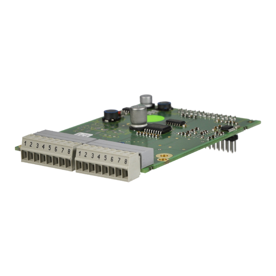
- Page 1 COMBIVERT INSTRUCTION MANUAL Encoder Interface variable Channel 1 HTL Output Channel 2 Mat.No. Rev. DLF5ZEM-K060...
-
Page 3: Table Of Contents
Table of Contents 1. Safety Instructions ..................4 Validity ........................4 1.2 Qualification ......................4 2. Product Description ..................5 General .......................5 Material number ....................5 Scope of delivery (option or replacement delivery) ..........5 Mechanical installation ..................6 3. Description of the Interface ................6 Voltage supply ....................6 Channel 1 ......................6 Channel 2 ......................7... -
Page 4: Safety Instructions
The used semiconductors and components of KEB are developed and dimensi- oned for the use in industrial products. If the KEB COMBIVERT is used in ma- Use under spe-... -
Page 5: Product Description
General Each of the interface cards delivered by KEB include two interfaces. As there are numerous different combinations available each interface will be described by means of separate instructions. The instruction covers the installation of the interface card, the connection as well as the start-up of a suitable encoder. -
Page 6: Mechanical Installation
Encoder Interface HTL Output on Channel 2 Mechanical installation All kind of works on the inverter may be carried out by authorized personnel in accordance with the EMC and safety rules only. • Switch inverter de-energized and await capacitor discharge time •... -
Page 7: Channel 2
Encoder Interface HTL Output on Channel 2 Channel 2 Terminal strip Interface type Incremental encoder simulation (output) HTL 20…26 V (input voltage - 4 V) Output signals max. 30 mA per output (briefly short-circuit proof) Outputs / tracks A+, A-, B+, B-, N+, N- Input Voltage input for HTL signal level Increments per revolution programmable 50 m, the value is additionally limited by the signal fre-... -
Page 8: Output Signals Channel 2
Encoder Interface HTL Output on Channel 2 3.3.2 Output signals channel 2 At the HTL encoder simulation the signal tracks A and B are electrically phase-shifted by 90°. The output signals can be connected optionally as difference signal with the respective inverse tracks or as single-ended signals. The zero signal is output once per revolution with the same level. - Page 9 Notices GB-9...
- Page 10 +39 02 33535311 • fax: +39 02 33500790 net: www.keb.it • mail: kebitalia@keb.it KEB Power Transmission Technology (Shanghai) Co.,Ltd. No. 435 QianPu Road, Songjiang East Industrial Zone, KEB Japan Ltd. CHN-201611 Shanghai, P.R. China 15–16, 2–Chome, Takanawa Minato-ku fon: +86 21 37746688 • fax: +86 21 37746600 J–Tokyo 108-0074...
Need help?
Do you have a question about the COMBIVERT F5 and is the answer not in the manual?
Questions and answers