
Related Manuals for SRAM Reverb Stealth


Summary of Contents for SRAM Reverb Stealth
- Page 1 Reverb™ Stealth & s e r v i c e m a n u a l GEN.0000000005341 Rev A © 2017 SRAM, LLC...
- Page 2 LIMITATIONS OF LIABILITY To the extent allowed by local law, except for the obligations specifically set forth in this warranty statement, in no event shall SRAM or its third party suppliers be liable for direct, indirect, special, incidental, or consequential damages.
- Page 3 SAFETY FIRST! We care about YOU. Please, always wear your safety glasses and protective gloves when servicing RockShox® products. Protect yourself! Wear your safety gear!
-
Page 4: Table Of Contents
TABLE OF CONTENTS PRODUCT IDENTIFICATION - REVERB™ STEALTH ....................................6 RECOMMENDED SERVICE INTERVALS ........................................7 SERVICE HISTORY ................................................7 BRASS KEY SIZE ................................................7 TORQUE VALUES ................................................8 PARTS, TOOLS, AND SUPPLIES ..........................................9 EXPLODED VIEW - ASSEMBLY ..................................10 EXPLODED VIEW - COMPONENT ..................................11 SEATPOST SERVICE ......................................12 SEATPOST REMOVAL .............................................. - Page 5 Replace the o-ring or seal with a new one from the service kit. Use your fingers or a pick to pierce and remove the old seal or o-ring. Apply only SRAM Butter grease to the new seal or o-ring. NOTI CE Do not scratch any sealing surfaces when servicing the product.
-
Page 6: Product Identification - Reverb™ Stealth
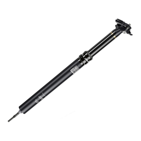
P r o d u c t I d e n t i f i c a t i o n - R e v e r b ™ S t e a l t h Production versions of Reverb Stealth can be identified visually. Your Reverb A2 - Upper Post - No RockShox®... -
Page 7: Recommended Service Intervals
Extends wiper seal, top cap bushing, and brass key lifespan Perform remote lever bleed Ensures proper remote actuation function Replace all parts included in the Reverb Stealth A2 Restores hydraulic system and function Service Kit - 200 hours Every 200 Hours... -
Page 8: Torque Values
T o r q u e V a l u e s Part Tool Torque Poppet valve housing 5.7-7.9 N•m (50-70 in-lb) 11 mm open end wrench Internal seal head 23 mm open end wrench 28 N•m (250 in-lb) Poppet valve cover 5.7-7.9 N•m (50-70 in-lb) 10 mm open end wrench Top cap assembly... -
Page 9: Parts, Tools, And Supplies
Bicycle Tools • Reverb™ Stealth B1 Service Kit - 200 hours • Bicycle work stand • Reverb Stealth B1 Service Kit - 400 hours • Park Tool® AV-5 Axle and Spindle Vise Inserts Tools • Reverb Stealth A2 Service Kit - 200 hours •... -
Page 10: Exploded View - Assembly
Internal Seal Head Lower Post Inner Shaft Assembly Bottomout O-ring Foam Ring Poppet Housing Base Plate Lock Ring Retaining Ring Poppet Valve Poppet Valve Housing Bleed Screw Poppet Valve Cover *Compatible with Reverb Stealth and Reverb Exploded View - Assembly... -
Page 11: Exploded View - Component
Coupler Collar Poppet Valve Hose Barb Lock Ring Housing Sleeve Internal Floating Piston (IFP) B1 Internal Floating Piston (IFP) A2 Retaining Ring A2 Retaining Ring B1 Hydraulic Hose Connectamajig Hose Coupler *Compatible with Reverb Stealth and Reverb Exploded View - Component... -
Page 12: Seatpost Service
S e a t p o s t S e r v i c e S e a t p o s t R e m o v a l Secure the bicycle in an upright position. NOTI CE The Reverb™ Stealth seatpost will be removed from the bicycle. Do not clamp the seatpost in a bicycle work stand. - Page 13 Set the Speed adjuster to the full slow position. Reverb 1x Remote Rotating the Speed adjuster to the slowest setting is critical for a successful bleed. Failure to do so may result in insufficient fluid volume inside the hydraulic remote system. Standard Remote: Turn the Speed adjuster knob in the opposite direction of the arrow (counter-clockwise) until it stops.
- Page 14 Record your saddle settings for reference when the saddle is installed back onto the seatpost. Remove the saddle clamps and saddle. 4 mm Remove the air cap. 9 mm Depress the Schrader valve and release all air pressure from the air chamber.
- Page 15 Loosen the seatpost collar. Remove the seatpost from the bicycle seat tube while simultaneously Frame Hose Port pushing the hydraulic hose into the hose port in the bicycle frame. The hose port location will vary depending on the bicycle frame. Consult with your frame manufacturer for additional information.
-
Page 16: Hydraulic Hose Disconnect
The hydraulic hose must be disconnected from the seatpost for all service procedures. Follow the procedure below for the hose type on your Reverb Stealth. The hose does not need to be disconnected from the remote lever for seatpost service. -
Page 17: Lower Post Removal
5 0 / 2 0 0 / 4 0 0 u r S e r v i c e L o w e r P o s t R e m o v a l N OTIC E Use bench vise soft jaw inserts to prevent damage to the seatpost or any seatpost component when clamping it into a vise. Clamp each component only tight enough to prevent it from spinning in the soft jaws. - Page 18 Clamp the poppet housing wrench flats tightly in a vise with flat soft jaw inserts. Remove the lock ring from the poppet valve housing. 26 mm A2: Remove the lock ring o-ring. Clean the lock ring and o-ring. Apply grease to the o-ring and reinstall it. Remove the seatpost from the vise.
- Page 19 A2: Push the volume spacer from the lower post with a dowel. 355 mm & 420 mm (100 mm Travel), 420 mm (125 mm Travel) Clamp the upper post head into the vise with flat soft jaws. Remove the three brass keys from the upper post. page 7, record the number of lines, which indicate key size, marked on the brass keys for future reference.
-
Page 20: 200 (B1) Hour Service
2 0 0 ( B 1 ) H o u r S e r v i c e T o p C a p a n d S e a l H e a d B u s h i n g R e p l a c e m e n t The following steps are to be completed during the B1 200 hour service interval and include replacing parts included in the Reverb™... - Page 21 Spray isopropyl alcohol onto the upper post and inner shaft assembly and wipe them with a clean shop towel. Apply a liberal amount of SRAM® Butter grease around the inside of a new top cap assembly and onto the seals.
- Page 22 Install a new bottomout o-ring and foam washer over the poppet valve housing assembly and onto the inner shaft. NOTI CE Do not damage the foam washer during installation. To continue with the 200 (B1) Hour Service proceed to Brass Key Installation.
-
Page 23: Inner Shaft Disassembly
2 0 0 ( A 2 ) & 4 0 0 ( B 1 ) H o u r S e r v i c e I n n e r S h a f t D i s a s s e m b l y ⚠... - Page 24 Wrap a shop towel around the upper post below the seal head. Unthread the internal seal head three full turns. Do not remove the seal head. 23 mm Wrap a shop towel around and over the internal seal head. Slowly unthread the seal head by hand while holding the shop towel over the seal head.
- Page 25 Spray the inner shaft and RockShox® 3-hole vise blocks with isopropyl 11 mm alcohol and wipe them with a clean shop towel. The clamping surfaces must be free of oil and grease. Clamp the inner shaft into the 10 mm slot in the RockShox 3-hole vise blocks.
-
Page 26: Upper Post Disassembly
2 0 0 ( A 2 ) & 4 0 0 ( B 1 ) H o u r S e r v i c e U p p e r P o s t D i s a s s e m b l y Clamp the upper post head into the vise with flat soft jaws. - Page 27 Remove the internal floating piston (IFP) from the upper post. Insert seven to nine plastic cable ties (cable tie size may vary), one at a time, into the upper post and through the center of the IFP. Pull the cable ties out of the upper post and remove the IFP. Discard the IFP.
-
Page 28: Top Cap Installation
Slide the top cap assembly down until it is positioned below the upper post key slots. Apply a light coat of SRAM Butter grease to the outside of the upper post, above the top cap assembly. NOTI CE Ensure the dust wiper seal slides over the upper post without folding the outer lip of the seal. -
Page 29: Internal Floating Piston (Ifp) Installation
The IFP tube should be below the top of the upper post when it is installed correctly. Apply a very liberal amount of SRAM® Butter grease to the new B1 IFP. Fill the groove on both sides of the IFP, and coat the outer and inner surfaces. - Page 30 Reverb IFP height tool may vary. Always measure from the bottom of the tool and mark the tool with the correct IFP depth for the Reverb Stealth seatpost being serviced. Set the internal floating piston (IFP) height. Use the Reverb IFP height tool to push the IFP down into the upper post.
-
Page 31: Inner Shaft Assembly
Do not scratch the inner shaft piston with the pick. Pick Apply a liberal amount of SRAM Butter grease to the inside of a new internal seal head assembly. Install the internal seal head assembly onto the inner shaft, threaded end first. - Page 32 A2 (355 mm x 100 mm, 420 mm x 100 mm, 420 mm x 125 mm): Apply SRAM® Butter to the volume spacer o-ring. Install a new bottomout o-ring, the volume spacer, and a new foam ring, in that order, onto the inner shaft.
-
Page 33: Inner Shaft Installation
200 (A2) & 400 (B1) Hour Service I n n e r S h a f t I n s t a l l a t i o n Clamp the upper post head back into the vise and flat soft jaws. Reverb Hydraulic Fluid Wrap a shop towel around the top of the upper post. - Page 34 Tighten the seal head. Use a shop towel to wipe away any excess fluid. NOTI CE Do not scratch the inner shaft with the wrench as this is a critical sealing surface. Surface scratches can cause leaks and reduce performance. Do not compress the inner shaft into the upper post and IFP tube until the seatpost is completely reassembled.
-
Page 35: Poppet Valve Installation
A specific amount of Reverb™ hydraulic fluid must be removed from the inner shaft before the poppet valve is installed. Consult the chart below and set the fluid level height for your Reverb Stealth configuration on the suspension fluid level gauge tool. - Page 36 Remove the poppet valve cover o-ring. Install a new o-ring onto the poppet valve cover and apply SRAM® Butter grease to the new o-ring. Pick Install the poppet valve cover onto the poppet valve housing and thread it on by hand.
-
Page 37: Lower Post Installation
L o w e r P o s t I n s t a l l a t i o n Apply a liberal amount of SRAM® Butter grease onto the seal head bushing. Apply a liberal amount of SRAM Butter grease to the inside of the lower post tube. Install the lower post onto the upper post. -
Page 38: Brass Key Installation
Install new brass keys into the key slots. The orientation of the brass keys is not critical. Apply a liberal amount of SRAM Butter grease onto the brass keys and upper post. Slide the top cap up and down to lubricate the top cap seal. - Page 39 Align the lower post key slots with the brass keys and ensure the laser etched RockShox® logo is aligned with the back of the seatpost head. Key Slots Hold each brass key in place and slide the lower post down until it engages the keys.
-
Page 40: Lock Ring And Retaining Ring Installation
5 0 / 2 0 0 / 4 0 0 u r S e r v i c e L o c k R i n g a n d R e t a i n i n g R i n g I n s t a l l a t i o n Clamp the lower post back into the vise and Park Tool®... -
Page 41: Pressurize Seatpost
5 0 / 2 0 0 / 4 0 0 u r S e r v i c e P r e s s u r i z e S e a t p o s t Clamp the seatpost back into the vise and Park Tool® AV-5 vise inserts 9 mm with the post head facing up. -
Page 42: Remote Lever
If the hydraulic hose assembly is removed from the bicycle, refer to the 'Reverb™ Stealth and Reverb Hydraulic Hose Replacement and Remote System Bleed' manual at www.sram.com/service for installation procedures. For a list of available Reverb Stealth hydraulic hose kits, refer to the RockShox® Spare Parts catalog at www.sram.com/service. N OTIC E If Reverb hydraulic fluid leaks from the remote lever while under pressure or in use, the remote lever assembly must be replaced. - Page 43 Standard Remote: Unthread the barb from the remote and discard it. 6 mm Standard Remote Install a new hose barb and tighten it. Proceed to step 8. 6 mm 2.9-3.5 N•m (25-30 in-lb) Reverb™ 1x™ Remote: Remove the compression nut. Remove the hose barb and discard it.
- Page 44 Reverb™ 1x™ Remote: Cut 3 - 4 mm off the end of the hose. Hydraulic Hose Cutters Reverb 1x Remote: Insert the compression nut onto the hose. Thread a new hose barb into the hose until it stops. NOTI CE Do not over-tighten and strip the threads inside the hydraulic hose.
- Page 45 The Reverb remote hydraulic system must be bled after the hose is installed onto the remote lever. Refer to the 'Reverb Stealth and Reverb Hydraulic Hose Replacement and Remote System Bleed' manual, available at www.sram.com/service, for hydraulic remote system bleed...
-
Page 46: Hydraulic Hose
There are two Reverb™ Stealth hydraulic hose types: 1) Hose barb, and 2) Connectamajig™. Follow the procedure in step 2 for the hose type on your Reverb Stealth. Use wire cutters to cut the cable tie used to secure the remote lever to Wire Cutters Reverb 1x™... - Page 47 This concludes service for the RockShox® Reverb™ Stealth adjustable height seatpost. The Reverb Stealth hydraulic remote system must be bled before the seatpost can be reinstalled and used. Refer to the 'Reverb Stealth and Reverb Hydraulic Hose Replacement and Remote System Bleed' manual, available at www.sram.com/service, for bleed and seatpost installation procedures.
- Page 48 This publication includes trademarks and registered trademarks of the following companies: TORX® is a registered trademark of Acument Intellectual Properties, LLC. Park Tool® is a registered trademark of Park Tool Co.
- Page 49 ASIAN HEADQUARTERS WORLD HEADQUARTERS EUROPEAN HEADQUARTERS SRAM Taiwan SRAM LLC SRAM Europe No. 1598-8 Chung Shan Road 1000 W. Fulton Market, 4th Floor Paasbosweg 14-16 Shen Kang Hsiang, Taichung City Chicago, Illinois 60607 3862ZS Nijkerk Taiwan R.O.C. The Netherlands...
Need help?
Do you have a question about the Reverb Stealth and is the answer not in the manual?
Questions and answers