Table of Contents
Advertisement
Quick Links
Advertisement
Table of Contents

Related Manuals for SRAM RSC


Summary of Contents for SRAM RSC
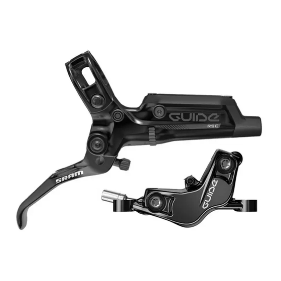
- Page 1 2017 Guide™ RSC Service Manual GEN.0000000005189 Rev C © 2017 SRAM, LLC...
- Page 2 LIMITATIONS OF LIABILITY To the extent allowed by local law, except for the obligations specifically set forth in this warranty statement, in no event shall SRAM or its third party suppliers be liable for direct, indirect, special, incidental, or consequential damages.
-
Page 3: Table Of Contents
CALIPER PISTON REMOVAL ............................................9 CALIPER PISTON INSTALLATION ..........................................12 LEVER SERVICE .........................................15 PARTS AND TOOLS NEEDED FOR SERVICE......................................15 GUIDE RSC EXPLODED VIEW ............................................ 15 LEVER BLADE REMOVAL............................................. 16 PISTON ASSEMBLY REMOVAL ..........................................19 PISTON ASSEMBLY INSTALLATION ........................................22 LEVER BLADE INSTALLATION ..........................................26... - Page 4 SAFETY FIRST! We care about YOU. Please, always wear your safety glasses and protective gloves when servicing SRAM products. Protect yourself! Wear your safety gear!
-
Page 5: Brake Service Overview
• Do not allow any brake fluid to come in contact with the brake pads. If this occurs, the pads are contaminated and must be replaced. • For best results, use only SRAM High-Performance DOT 5.1 brake fluid. If SRAM brake fluid is not available, only use DOT 5.1 or 4 brake fluid. -
Page 6: Troubleshooting
T r o u b l e s h o o t i n g If your levers have excessive brake lever throw, it may be a result of the pistons sticking in the caliper. Before bleeding the system, you can try to loosen the sticky piston by performing the following steps: Clamp the bicycle into a bicycle work stand. -
Page 7: Caliper Service
C a l i p e r S e r v i c e We recommend that you have your SRAM Guide™ brakes serviced by a qualified bicycle mechanic. Servicing SRAM brakes requires knowledge of brake components as well as the special tools and oils used for service. -
Page 8: Caliper Brake Pad Removal
C a l i p e r B r a k e P a d R e m o v a l N OT ICE DOT fluid will damage painted surfaces. If any fluid comes in contact with a painted surface (i.e. your frame) or printing on the brakes, wipe it off immediately and clean it with isopropyl alcohol or water. -
Page 9: Caliper Piston Removal
C a l i p e r P i s t o n R e m o v a l N OT ICE DOT fluid will damage painted surfaces. If any fluid comes in contact with a painted surface (i.e. your frame) or printing on the brakes, wipe it off immediately and clean it with isopropyl alcohol or water. - Page 10 Remove the Guide™ pad spreader. 2.5 mm hex wrench Use a 2.5 mm hex wrench to remove the pad retention bolt. ® Use a T25 TORX wrench to remove each caliper body bolt. T25 TORX wrench Separate the caliper body halves. Set the heat shield aside.
- Page 11 Remove the pistons from each caliper body half. Use a pick to remove the piston seals from each caliper body half. Install new seals inside each caliper body half. ⚠ WARNI NG Do not scratch the seal gland with the pick. Scratches could cause fluid to leak when the brake is applied, which will contaminate the brake pads and could lead to a brake failure.
-
Page 12: Caliper Piston Installation
NOT ICE For the best braking performance, use only SRAM High-Performance 5.1 DOT fluid. If SRAM fluid is not available, use only DOT 5.1 or 4 fluid. Do not use grease. Grease will prevent the pistons from fully retracting into the caliper bores which will reduce braking performance. - Page 13 4.4-5.4 N·m (39-48 in-lb). T25 TORX bit 4.4-5.4 N·m (39-48 in-lb) Remove the o-rings from the banjo bolt and banjo fitting. Apply a small amount of SRAM High-Performance 5.1 DOT fluid to the new o-rings and install them. Caliper Piston Installation...
- Page 14 Hold the banjo at the desired angle. ® Use a torque wrench with a T25 TORX bit socket to tighten the bolt to 4.4-5.4 N·m (39-48 in-lb). T25 TORX bit 4.4-5.4 N·m (39-48 in-lb) Insert the Guide™ bleed block into the caliper. Bleed block Use a 2.5 mm hex wrench to install the pad retention bolt ⚠...
-
Page 15: Lever Service
• SRAM High-Performance DOT 5.1 fluid. If SRAM fluid is not available, only use DOT 5.1 or 4 fluid. • SRAM or AVID DOT grease. If SRAM or AVID DOT grease is not available only use a DOT compatible grease. -
Page 16: Lever Blade Removal
Install new seals and a new hose. For best results, use only SRAM High-Performance DOT 5.1 fluid. If SRAM fluid is not available, only use DOT 5.1 or 4 fluid. Lever Blade Removal... - Page 17 Use a T10 TORX® wrench to remove the reservoir cap bolt nearest to the lever blade. T10 TORX wrench Carefully turn the lever body upside down so that the detent spring and ball fall out of the lever body. If they do not initially fall out, gently tap the lever against a clean rag.
- Page 18 Pour the fluid from the brake lever body into a pan. Separate the bladder from the reservoir cover. Spray isopropyl alcohol on the bladder and the reservoir cover and clean them with a rag. NOT ICE All components must be completely dry before reinstalling them. Moisture residue from cleaning the bladder can leak out of the bladder as it dries, which can be misinterpreted as a system leak.
-
Page 19: Piston Assembly Removal
P i s t o n A s s e m b l y R e m o v a l Use a T8 TORX® wrench to remove the SwingLink™ pinch bolt. T8 TORX wrench Use a T8 TORX wrench to push the SwingLink pivot pin out of the lever body. - Page 20 Remove the SwingLink™ bushings by hand. Use a SRAM Guide™ Lever Internals Assembly Tool to unthread the piston sleeve and coupler. Insert the SRAM Guide Lever Internals Assembly Tool into the lever body and align the keyslot of the tool with the piston sleeve.
- Page 21 Place a rag over the lever body to prevent the piston assembly spring from forcefully ejecting. Use your hand to push out the contact adjust knob. ⚠CAUTI ON - EYE HA ZARD Use safety glasses. The piston assembly is spring loaded and will forcefully eject from the lever body when the contact knob is removed.
-
Page 22: Piston Assembly Installation
Damage to painted and/or printed surfaces by DOT fluid is not covered under warranty. Submerge the new piston assembly in SRAM High-Performance DOT 5.1 fluid. You can also use SRAM DOT Assembly Grease, or DOT 5.1 or 4 compatible grease, as a lubricant. SRAM High-Performance DOT 5.1 Fluid Install the new lubricated piston assembly into the lever body. - Page 23 Place the sleeve on the coupler. The sleeve threads must be oriented away from the base of the coupler. Use the SRAM Guide™ Lever Internals Assembly Tool tool to engage T8 TORX wrench and thread the sleeve and coupler onto the piston assembly.
- Page 24 Use a 2 mm hex wrench to tighten the push rod into the SwingLink. SRAM Guide Lever Internals Assembly Tool 2 mm hex wrench Use a 2 mm hex wrench to remove the SwingLink from the SRAM Guide Lever Internals Assembly Tool and place the pushrod into the coupler sleeve.
- Page 25 Align the holes of the SwingLink™ and the SwingLink bushings, then press the pivot pin into the hole until it is flush with the lever body. Apply a small amount of Loctite® Threadlocker Blue 242® onto the T8 TORX wrench pinch bolt.
-
Page 26: Lever Blade Installation
L e v e r B l a d e I n s t a l l a t i o n Install the lever blade. Line up the pivot holes of the lever blade with the pivot holes in the lever body. - Page 27 Use a torque wrench and a T10 TORX® bit socket to tighten each pivot bolt to 2.7-3.2 N·m (24-28 in-lb). T10 TORX bit 2.7-3.2 N•m (24-28 in-lb) 22 m Press the bladder into the reservoir cap, make sure the bladder is properly seated into the reservoir cap.
- Page 28 You must install a new hose barb and compression fitting before recon- necting the brake lever to the hose. SRAM Hydraulic Hose Cutter Apply DOT grease to the hose barb threads. Thread the hose barb into the hose until it is flush with the end of the hose.
- Page 29 Servicing your brakes removes all of the fluid from the system. You must bleed the brakes after you service the brake caliper and/or lever. For brake bleed, brake hose shortening, and brake pad replacement instructions, visit www.sram.com/service. Lever Blade Installation...
-
Page 30: Disc Brake Pad And Rotor Bed-In Procedure
D i s c B r a k e P a d a n d R o t o r B e d - i n P r o c e d u r e All new brake pads and rotors should be put through a wear-in process called 'bed-in'. The bed-in procedure, which should be performed prior to your first ride, ensures the most consistent and powerful braking feel along with the quietest braking in most riding conditions. - Page 31 This publication includes trademarks and registered trademarks of the following companies: TORX® is a registered trademark of Acument Intellectual Properties, LLC. Loctite® and Threadlocker Blue 242® are registered trademarks of Henkel Corporation...
- Page 32 ASIAN HEADQUARTERS WORLD HEADQUARTERS EUROPEAN HEADQUARTERS SRAM Taiwan SRAM LLC SRAM Europe No. 1598-8 Chung Shan Road 1000 W. Fulton Market, 4th Floor Paasbosweg 14-16 Shen Kang Hsiang, Taichung City Chicago, Illinois 60607 3862ZS Nijkerk Taiwan R.O.C. The Netherlands...
Need help?
Do you have a question about the RSC and is the answer not in the manual?
Questions and answers