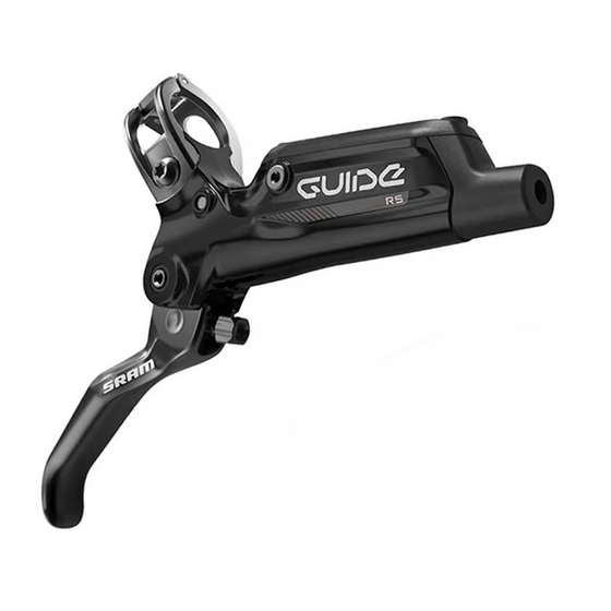
SRAM Guide R Service Manual
Brake system
Hide thumbs
Also See for Guide R:
- Service manual (32 pages) ,
- Service manual (41 pages) ,
- Service manual (58 pages)

Related Manuals for SRAM Guide R


Summary of Contents for SRAM Guide R
- Page 1 2017-2019 Guide™ RS & R s e r v i c e m a n u a l GEN.0000000005811 Rev C © 2021 SRAM, LLC...
- Page 2 LAW. FOR A FULL UNDERSTANDING OF YOUR RIGHTS, CONSULT THE LAWS OF YOUR COUNTRY, PROVINCE, OR STATE. EXTENT OF LIMITED WARRANTY Except as otherwise set forth herein, SRAM warrants its bicycle components to be free from defects in materials or workmanship for a period of two (2) years after original purchase of the product.
-
Page 3: Table Of Contents
TABLE OF CONTENTS SRAM® GUIDE™ BRAKE SYSTEMS SERVICE ..............................5 SERVICE PROCEDURES ..............................................6 TROUBLESHOOTING ......................................7 CALIPER SERVICE .......................................8 PARTS AND TOOLS NEEDED FOR SERVICE......................................8 CALIPER EXPLODED VIEW ............................................8 CALIPER BRAKE PAD REMOVAL ..........................................9 CALIPER PISTON REMOVAL ............................................10 CALIPER PISTON INSTALLATION ..........................................13 LEVER SERVICE .........................................16... - Page 4 SAFETY FIRST! We care about YOU. Please, always wear your safety glasses and protective gloves when servicing SRAM® products. Protect yourself! Wear your safety gear!
-
Page 5: Sram® Guide™ Brake Systems Service
SRAM brake systems need to be serviced periodically to optimize braking function. If brake fluid is leaking from any area of the brake there may be damage or wear and tear to the internal moving parts. -
Page 6: Service Procedures
S e r v i c e P r o c e d u r e s The following procedures should be performed throughout service, unless otherwise specified. Clean the part with isopropyl alcohol and a clean, lint-free rag. Clean the sealing surface on the part and inspect it for scratches. Replace the o-ring or seal with a new one from the service kit. -
Page 7: Troubleshooting
T r o u b l e s h o o t i n g NOT ICE Do not apply DOT brake fluid or grease to caliper pistons when performing troubleshooting procedures. Use of DOT brake fluid or grease can diminish braking performance and cause rotor rubbing. -
Page 8: Caliper Service
• Pad Spreader Tool (1.8 mm) - Guide available, only use DOT 5.1 or 4 brake fluid. • SRAM or AVID® DOT grease. If SRAM or AVID DOT grease is not available only use a DOT compatible grease. C a l i p e r E x p l o d e d V i e w... -
Page 9: Caliper Brake Pad Removal
C a l i p e r B r a k e P a d R e m o v a l Use a T25 TORX® wrench to remove the brake caliper from the fork or frame. Remove the caliper mounting bracket and hardware from the caliper then set them aside in the order that they were removed. -
Page 10: Caliper Piston Removal
C a l i p e r P i s t o n R e m o v a l N OT ICE DOT brake fluid will damage painted surfaces. If any fluid comes in contact with a painted surface (e.g your frame) or printing on the brakes, wipe it off immediately and clean it with isopropyl alcohol or water. - Page 11 Remove the Guide™ pad spreader. 2.5 mm hex wrench Remove the pad retention bolt. Remove each caliper body bolt. T25 TORX® wrench Separate the caliper body halves. Set the heat shield aside. Remove the caliper o-ring from the outboard side of the caliper. Caliper Piston Removal...
- Page 12 Remove the pistons from each caliper body half. Remove the piston seals from each caliper body half. Install new seals inside each caliper body half. ⚠WARNING Do not scratch the seal gland with the pick. Scratches could cause fluid to leak when the brake is applied, which will contaminate the brake pads and could lead to a brake failure.
-
Page 13: Caliper Piston Installation
NOTI CE For the best braking performance, use only SRAM High-Performance DOT 5.1 brake fluid. If SRAM fluid is not available, use only DOT 5.1 or 4 brake fluid. Do not use grease. Grease will prevent the pistons from fully retracting into the caliper bores which will reduce braking performance. - Page 14 T25 TORX bit 9.8-11.8 N·m (87-104 in-lb) 22 m Remove the o-rings from the banjo bolt and banjo fitting. Apply a small amount of SRAM® High-Performance DOT 5.1 brake fluid to the new o-rings and install them. Caliper Piston Installation...
- Page 15 ⚠ CAUTION Servicing your brakes removes all of the fluid from the system. You must bleed the brakes after you service the brake caliper and/or lever. For brake bleed and brake hose shortening instructions, visit www.sram.com/service. Caliper Piston Installation...
-
Page 16: Lever Service
P a r t s a n d T o o l s N e e d e d f o r S e r v i c e Parts Common Tools • Lever Internals Guide™ RS or Lever Internals Guide R/RE / DB5™ / • Pick with a 90 degree bent tip Code™ R •... -
Page 17: Guide™ R Lever Exploded View
G u i d e ™ R L e v e r E x p l o d e d V i e w Reservoir bolt Reservoir cap Push rod Piston assembly Snap ring Bladder (Stealth-a-majig™- OEM) Binder plug Washer Compression fitting Lever return spring Pinch bolt... -
Page 18: Lever Blade Removal
Install all new seals and a new hose. For best braking performance, use only SRAM® High-Performance DOT 5.1 brake fluid. If SRAM fluid is not available, use only High- Performance DOT 5.1 or 4 brake fluid. Lever Blade Removal... - Page 19 Remove the reservoir cap bolts from the reservoir cap. T10 TORX® wrench Remove the reservoir cover and bladder from the lever body. Pour the fluid from the brake lever body into a pan. Separate the bladder from the reservoir cover. Spray isopropyl alcohol on the bladder and the reservoir cover, then clean them with a rag.
- Page 20 Remove the binder plug. Pick Remove the pinch bolt. T8 TORX® wrench Use the T8 TORX wrench to push out the pivot pin. T8 TORX wrench Remove the lever blade from the lever body. The lever blade has four pieces, the lever blade, the cam/push rod assembly, a washer, and the lever return spring.
-
Page 21: Piston Assembly Removal
P i s t o n A s s e m b l y R e m o v a l Use a pick to remove the lever blade bushings from both sides of the lever. RS only: Use a T8 TORX® wrench to remove the SwingLink™ pivot pinch bolt. - Page 22 Use long-tipped internal snap ring pliers to apply downward pressure to the lever body and remove the snap ring. Turn the lever body upside down to allow the washer to fall out of the body. Internal snap ring pliers 20 mm or 15 mm Thru Axle Use needle nose pliers to remove the piston assembly.
-
Page 23: Piston Assembly Installation
Damage to painted and/or printed surfaces by DOT brake fluid is not covered under warranty. Submerge a new piston assembly in SRAM® High-Performance DOT 5.1 brake fluid. You can also use SRAM DOT Assembly Grease, or DOT 5.1 or 4 compatible grease, as a lubricant. SRAM High Performance DOT 5.1 brake fluid Install the new piston assembly into the lever body. -
Page 24: Rs Lever Blade Installation
R S L e v e r B l a d e I n s t a l l a t i o n Use needle nose pliers to install the SwingLink™ bushings. If the SwingLink bushings fall out easily, apply a small amount of DOT grease to the bushings to help hold them in place. - Page 25 Apply a small amount of Loctite® Threadlocker Blue 242® onto the 1.1-1.3 N·m (10-12 in-lbs) threads of the SwingLink™ pivot pinch bolt. Use a T8 TORX® wrench to thread the SwingLink pivot pinch bolt into the SwingLink. Tighten the SwingLink pivot pinch bolt to 1.1-1.3 N·m (9-12 in-lbs).
- Page 26 Apply a small amount of Loctite® Threadlocker Blue 242® onto the T8 TORX wrench pinch bolt. Loctite Threadlocker Blue 242 20 mm or 15 mm Thru Axle Use a T8 TORX® wrench to thread the pinch bolt into the lever body. Use a torque wrench and a T8 TORX bit socket to tighten the bolt to 1.1-1.3 N·m (9-12 in-lb).
- Page 27 You must install a new hose barb and compression fitting before recon- necting the brake lever to the hose. SRAM® Hydraulic Hose Cutter Apply DOT grease to the hose barb threads. Thread the hose barb into the hose until it is flush with the end of the hose.
- Page 28 Servicing your brakes removes all of the fluid from the system. You must bleed the brakes after you service the brake caliper and/or lever. For brake bleed, brake hose shortening, and brake pad replacement instructions, visit www.sram.com/service. RS Lever Blade Installation...
-
Page 29: R Lever Blade Installation
Steps to reassemble the R lever blade assembly: Place the washer on the cam/push rod assembly. You may add a dab of SRAM® DOT grease to hold the washer in place. Install the lever return spring onto the cam/push rod assembly. - Page 30 Insert the lever blade assembly into the lever body, placing the push rod into the piston and lever return spring on the lever body. Make sure the lever return spring is seated properly in the lever. The outboard end of the spring must press against the lever blade, while the inboard end of the spring must press against the lever body.
- Page 31 Use a torque wrench and a T8 TORX® wrench to tighten the bolt to 1.1-1.3 N·m (9-12 in-lb). T8 TORX 1.1-1.3 N•m (10-12 in-lb) 22 m Use a T8 TORX wrench to install a new binder bolt plug. T8 TORX wrench Press the bladder into the reservoir cap so that the bladder is properly seated and flush with the reservoir cap.
- Page 32 You must install a new hose barb and compression fitting before reconnecting the brake lever to the hose. SRAM® Hydraulic Hose Cutter Apply DOT grease to the hose barb threads. Thread the hose barb into the hose until it is flush with the end of the hose.
- Page 33 Servicing your brakes removes all of the fluid from the system. You must bleed the brakes after you service the brake caliper and/or lever. For brake bleed, brake hose shortening, and brake pad replacement instructions, visit www.sram.com/service. R Lever Blade Installation...
-
Page 34: Disc Brake Pad And Rotor Bed-In Procedure
(transfer layer) to the braking surface of the rotor. This transfer layer optimizes braking performance. To watch a video of the bed-in procedure, visit www.sram.com/service. - Page 35 PowerTap®, Qollector®, Quarq®, RacerMate®, Reba®, Rock Shox®, Ruktion®, Service Course®, ShockWiz®, SID®, Single Digit®, Speed Dial®, Speed Weaponry®, Spinscan®, SRAM®, SRAM APEX®, SRAM EAGLE®, SRAM FORCE®, SRAM RED®, SRAM RIVAL®, SRAM VIA®, Stylo®, Torpedo®, Truvativ®, TyreWiz®, Varicrank®, Velotron®, X0®, X01®, X-SYNC®, XX1®, Zed tech®, Zipp®...
- Page 36 ASIAN HEADQUARTERS WORLD HEADQUARTERS EUROPEAN HEADQUARTERS SRAM Taiwan SRAM LLC SRAM Europe No. 1598-8 Chung Shan Road 1000 W. Fulton Market, 4th Floor Paasbosweg 14-16 Shen Kang Hsiang, Taichung City Chicago, Illinois 60607 3862ZS Nijkerk Taiwan R.O.C. The Netherlands...
Need help?
Do you have a question about the Guide R and is the answer not in the manual?
Questions and answers