Table of Contents
Advertisement
Quick Links
Advertisement
Table of Contents

Subscribe to Our Youtube Channel
Related Manuals for HySecurity Nice 3501


Summary of Contents for HySecurity Nice 3501
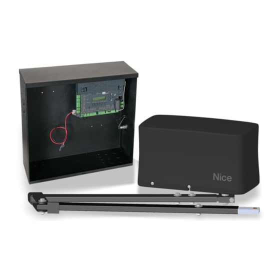
- Page 1 Installation Manual 3501 Swing Vehicular swing gate articulating actuator/motor CHBOX35: ACTUATOR MOTOR CHASSIS ABOX35: ARTICULATING ACTUATOR www.hysecurity.com 800-321-9947 • 253-867-3700 • MX4754 REV. B ©2019 Residential | Commercial | Industrial | Anti-Ram | Parking...
-
Page 2: Table Of Contents
INSTRUCTION 13: INSTALL CONTROL BOX AND APPLY POWER ....20 INSTRUCTION 14: SET OPEN AND CLOSE LIMIT COLLARS ......... 21 INSTRUCTION 15: WELD OR BOLT GATE BRACKET TO GATE ......22 INSTRUCTION 16: MANUALLY OPENING THE GATE ........23 www.hysecurity.com • 800-321-9947 MX4754 Rev. B ©2019... -
Page 3: Section 1: 3501 Actuator Overview
ACTUATOR BOLT KIT 3500AAA ARM INSERT, ADJUSTABLE, ALUMINUM CHBOX35 ACTUATOR GATE BRACKET, MOTOR ACTUATOR HARDWARE (P/N 10025215) CHASSIS KIT (P/N 1125-35) ADJUSTABLE ALUMI- NUM ARM INSERT (P/N ACTUATOR 3500AAA) HARNESS CABLE ABOX35 ACTUATOR: www.hysecurity.com • 800-321-9947 MX4754 Rev. B ©2019... -
Page 4: Section 2: Installation Safety
1/2” and 3/8” wrench and/or nut driver • Basic hand tools (screwdrivers, pliers, etc..) • Bubble Level (for leveling actuator) • Measuring tape (for locating post position) • 1/8” and 5/32” hex keys (for set screws) www.hysecurity.com • 800-321-9947 MX4754 Rev. B ©2019... -
Page 5: Section 4: 3501 Actuator Mechanical Installation
TABLE 1-1: MOUNTING POST LOCATION CHART Approx. Open sec. to Inches Inches Inches Inches Degrees open 31.2 46.3 40.6 OPTIMUM 47.1 DIMENSIONS 42.1 13.5 25.5 46.3 46.8 47.1 43.7 42.4 53.5 37.4 50.6 39.3 58.4 44.3 50.3 www.hysecurity.com • 800-321-9947 MX4754 Rev. B ©2019... -
Page 6: Instruction 2: Determine Height Of Mounting Post
GATE STRUCTURAL SUPPORT 2” 2” TOP OF POST 2” ABOVE BRACKET CENTERLINE CENTERLINE OF GATE BRACKET POSITION MOUNTING POST IMAGE 2-1: DETERMINING HEIGHT OF MOUNTING POST www.hysecurity.com • 800-321-9947 MX4754 Rev. B ©2019... -
Page 7: Instruction 3: Weld Mounting Bracket To Post
REMOVE BOTH END SCREWS (x2) 1/2” LOCK WASHER (x4) MOUNTING BRACKET 1/2”-13x3/4” HEX BOLT (x4) IMAGE 3-1: REMOVING COVER AND MOUNTING BRACKET FROM CHASSIS MOUNTING BRACKET POST IMAGE 3-2: WELD MOUNTING BRACKET TO POST www.hysecurity.com • 800-321-9947 MX4754 Rev. B ©2019... -
Page 8: Instruction 4: Mount Chassis To Post
GATE connection is on the opposite side of mounting plate from the gate when in the closed position. MAIN DRIVE SHAFT IMAGE 4-2: PROPER ORIENTATION OF CHASSIS TO GATE www.hysecurity.com • 800-321-9947 MX4754 Rev. B ©2019... -
Page 9: Instruction 5: Mount Primary Arm Collar To Drive Shaft
RETAINING RING DETAIL RETAINING RING NOTE: retaining INSTALLED IN ring is included in DRIVE SHAFT hardware kit 1125- GROOVE BOTTOM VIEW 1/2” HEX NUT IMAGE 5-2: PRIMARY ARM COLLAR MOUNTED TO MAIN DRIVE SHAFT www.hysecurity.com • 800-321-9947 MX4754 Rev. B ©2019... -
Page 10: Instruction 6: Attach Primary Arm To Arm Collar
BOTTOM VIEW BOLT WASHER INSTALL USING 1/2”-13x1-3/4” HEX BOLT (x2) 1/2” WASHERS (x4) & 1/2”-13 HEX NUTS (x2) WASHER IMAGE 6-2: PRIMARY ARM INSTALLED TO COLLAR OF THE MAIN DRIVE SHAFT (BOTTOM VIEW) www.hysecurity.com • 800-321-9947 MX4754 Rev. B ©2019... -
Page 11: Instruction 7: Assemble Arm Assembly
1/2” LOCK NUT BOLT WASHER SECONDARY WASHER • 1/2”-13x2” HEX BOLT • 1/2” WASHER (x2) • 1/2” LOCK NUT IMAGE 7-1: NOTE: This hardware is included ARM ASSEMBLY - EXPLODED VIEW in hardware kit 1125-35. www.hysecurity.com • 800-321-9947 MX4754 Rev. B ©2019... - Page 12 IMAGE 7-3: INSTALL ALUMINUM ADJUSTABLE ARM TO SECONDARY ARM NOTE: Once limits are set and the board has been programmed, this aluminum arm can be adjusted to fine tune the closed gate position. www.hysecurity.com • 800-321-9947 MX4754 Rev. B ©2019...
-
Page 13: Instruction 8: Affix Gate Bracket To Actuator Arm
ACTUATOR ARM BRACKET 1/2” WASHERS 1/2” LOCK NUT GATE BRACKET 1/2”-13x3” BOLT 1/2” WASHER 1/2” WASHER ACTUATOR ARM 1/2” LOCK NUT IMAGE 8-1: GATE BRACKET TO ACTUATOR ARM USING BOLT, WASHER, & NUT www.hysecurity.com • 800-321-9947 MX4754 Rev. B ©2019... - Page 14 3: AFFIX GATE BRACKET TO ACTUATOR ARM (CONT.) HITCH PIN HOLE FOR R-CLIP ACTUATOR R-CLIP (INSERT INTO HITCH PIN HOLE) HITCH PIN GATE BRACKET ACTUATOR ARM R-CLIP IMAGE 8-2: GATE BRACKET TO ACTUATOR ARM USING HITCH PIN AND R-CLIP www.hysecurity.com • 800-321-9947 MX4754 Rev. B ©2019...
-
Page 15: Instruction 9: Install Gate Bracket To Gate Support
IMAGE 9-2: ENSURING PRIMARY ARM LOCKED INTO STOP TAB OF SECONDARY ARM NOTE: Permanent welds or bolt attachment should be completed once limits are set. www.hysecurity.com • 800-321-9947 MX4754 Rev. B ©2019... -
Page 16: Section 5: Actuator Wiring Connections
LIMIT SWITCH ASSEMBLY MOTOR TOGGLE SWITCH TERMINAL STRIP Orange ACTUATOR White HARNESS White TO/FROM 1050 White CONTROL Green BOARD White (x2) Black Black Black Black IMAGE 10-1: WIRING ACTUATOR TO CHASSIS TERMINAL STRIP www.hysecurity.com • 800-321-9947 MX4754 Rev. B ©2019... -
Page 17: Instruction 11: Run Actuator Cable(S) To Control Box
4. Run the 2nd cable into a hole (with rubber grommet) into the bottom of the control box. NOTE: Ensure the cable(s) reaches into the control box sufficiently to reach the MOTOR inputs on the control board. www.hysecurity.com • 800-321-9947 MX4754 Rev. B ©2019... -
Page 18: 5.2 Control Board Wiring
(red & black wires) for that motor. MOTOR 1 3501 ACTUATOR BLACK MOTOR LEADS IMAGE 12A-1: LEFT OPENING GATE: ACTUATOR TO CONTROL BOARD WIRING www.hysecurity.com • 800-321-9947 MX4754 Rev. B ©2019... - Page 19 (red & black wires) for that motor. MOTOR 1 3501 ACTUATOR MOTOR LEADS BLACK IMAGE 12B-1: RIGHT OPENING GATE: ACTUATOR TO CONTROL BOARD WIRING www.hysecurity.com • 800-321-9947 MX4754 Rev. B ©2019...
-
Page 20: Instruction 12C: Wire Actuator Cable To Control Board (Dual)
However, if this switch is inadvertantly turned OFF during installation, the motor will not operate. See INSTRUCTION 16, IMAGE 16-1 for switch location and ON/OFF orientation in case this is an issue. www.hysecurity.com • 800-321-9947 MX4754 Rev. B ©2019... -
Page 21: Instruction 14: Set Open And Close Limit Collars
5. Rotate the CLOSE Limit collar by hand until the appropriate Limit LED illuminates RED on the control board (IMAGE 14-2). The fully CLOSED limit switch is now set. Re-tighten set screw. NOTE: If both limits are active simultaneously, the limit LED will appear orange www.hysecurity.com • 800-321-9947 MX4754 Rev. B ©2019... -
Page 22: Instruction 15: Weld Or Bolt Gate Bracket To Gate
IMPORTANT! Ensure bracket centerline is 2” BELOW the top of the mounting post for the actuator cassis. See IMAGE 2-1. GATE BRACKET 3/8” NUT (x2) 3/8”-16”x2-1/2” HEX BOLT (x2) BRACKET CENTERLINE IMAGE 15-1: GATE BRACKET AND HARDWARE www.hysecurity.com • 800-321-9947 MX4754 Rev. B ©2019... -
Page 23: Instruction 16: Manually Opening The Gate
MOTOR SWITCH DRIVE CHASSIS SHAFT IMAGE 16-1: MOTOR SWITCH LOCATION AND ON/OFF ORIENTATION NOTE: The motor switch should be used for manually moving of the gate whether the gate operator is powered or unpowered. www.hysecurity.com • 800-321-9947 MX4754 Rev. B ©2019... -
Page 24: Section 6: Part Drawings
10021790 Bracket, Gate Attach Kit 10021290 Bracket, Post Mount 10038315 Chassis Assembly, 3501 CHBOX35 Collar and Magnet 10021490 Cover, Plastic MX4774 Gearmotor 73090005 Limit Block Assembly 10058890 Toggle Switch 10024290 Torque Limiter 10040690 www.hysecurity.com • 800-321-9947 MX4754 Rev. B ©2019... - Page 25 3501 Actuator INSTALLATION REFERENCE MANUAL ABOX35 Arm Assembly Drawing www.hysecurity.com • 800-321-9947 MX4754 Rev. B ©2019...
-
Page 26: Section 7: Warranty
This warranty will be interpreted, construed, and enforced in all respects in the name plate of a manufacturer other than HySecurity or Nice and they are not a accordance with the laws of the State of Washington, without reference to its part of the base model. - Page 27 3501 Actuator INSTALLATION REFERENCE MANUAL (This page intentionally blank) www.hysecurity.com • 800-321-9947 MX4754 Rev. B ©2019...
- Page 28 Russ. INSTALLATION INFORMATION AND SIGN-OFFS Installation Acceptance Address where opener is located Installer name, number and address End user name and telephone number Contact us: Nice/HySecurity Kent, WA 98032 800-321-9947 hysecurity.com www.hysecurity.com • 800-321-9947 MX4754 Rev. B ©2019...
Need help?
Do you have a question about the Nice 3501 and is the answer not in the manual?
Questions and answers