Sign In
Upload
Manuals
Brands
HySecurity Manuals
Gate Opener
HydraSwing 40F
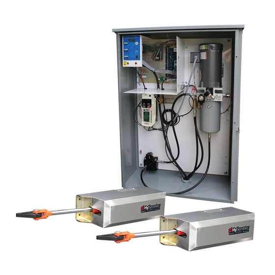
HySecurity HydraSwing 40F Manuals
Manuals and User Guides for HySecurity HydraSwing 40F. We have
5
HySecurity HydraSwing 40F manuals available for free PDF download: Programming And Operations Manual, Installation Instructions Manual
HySecurity HydraSwing 40F Programming And Operations Manual (136 pages)
with HySecurity Smart Touch Controller MX3636-01 Revision C
Brand:
HySecurity
| Category:
Gate Opener
| Size: 20.69 MB
Table of Contents
External Entrapment Protection Sensors Monitored by Hysecurity Gate Operators
3
Hydraswing Components
4
Hydrasupply Components
5
Table of Contents
7
Welcome to Hysecurity
13
Contact Information
14
Notices and Bulletins
14
Supplemental Documents
14
Important Safety Information
15
Safety - Additional Installer Responsibility
16
Safety - Additional Installer's Responsibility, Continued
17
Safety - Owner/User Responsibility
18
Hazardous Materials and Proper Disposal
18
Identifying Gate Operator Category and Usage Class
19
Breather Cap Installation and Grounding
20
Emergency Stop Button
21
Manual Release Option
21
Hand Pump: Manual Release
22
Wind Load Considerations
23
Safety Notices
24
Common Industrial Symbols
24
Power
25
Installing the Earth Ground
25
Gate Site Considerations
26
Wiring AC Power
26
Turning the Power Switch on
27
Wiring Diagram: Hydraswing/Hydrasupply
28
Wire Sizing and Runs
29
Low Voltage Control Wiring
29
Performance of Operators on 1 and 3 Phase 50/60Hz
30
UPS Backup Power Options
32
DC Power Supply (UPS) Connections
32
AC Power Supply with Hyinverter AC
33
Initial Setup
35
Open Position and Hydraulic Hose Swap
35
Setting the Close & Open Limits
36
Adjusting the Pressure Relief Valve
37
The Inherent Entrapment Sensor (IES)
38
Manufacturer's Responsibility
38
Pressure Relief Valve - All Hydraulic Operators
38
Inherent Entrapment Sensor - (IES)
39
Modbus RTU in Hydraswing
39
Emergency Fast Operate (EFO)
40
Setting the Emergency Fast Close
40
Installing a Push-Button Device for EFC
40
Entrapment Protection
41
Manufacturer's Responsibility
41
Pressure Relief Valve - All Hydraulic Operators
41
Inherent Entrapment Sensor System - Hydraulic Operators (IES)
42
The Inherent Entrapment Sensor (IES)
42
How Software Handles Monitoring External Entrapment Protection Sensors
43
External Entrapment Protection Sensors: What the Installer Needs to Do
43
Table 3: Changes to Sensor Inputs on the Controller
43
Entrapment Protection
44
Table 4: Installer Menu Settings for SENSOR Inputs
45
Supply Power to the Sensors
46
C Ontrol P Anel O Verview
47
STC Board, Power Supply Board and Display
48
Display & Menu Options
49
Understanding the Display and Keypad
49
Initial Setup
50
Initial Setup Using S.T.A.R.T
51
Menu Mode and the STC Keypad
52
Menu Mode Navigation
52
Run Mode and the STC Keypad
53
Viewing Gate Operator Scrolling Status
53
Stop the Status Display Scrolling
54
Change the Contrast on 7 Segment Displays
55
Display Power Saving Mode
55
Check the Software Version
55
Check Time and Date
55
User Menu
55
Installer Menu
58
Adjusting the Gate Speed
65
Resetting Open and Close Limits
66
Learn Close Limits
66
Learn Open Limits
66
Setting the Close Timer
67
Test the Operator
68
STC Inputs & Wiring
69
STC Input & Wiring
69
Overview of the STC and Power Supply Board
70
Integrating with Security Systems and Hynet™ Gateway
71
Smart Touch Controller Inputs
72
STC Terminal Inputs
72
Table 7: Programmable User Relays
75
User Relays - Programming Procedure
75
Hy8Relay Module Option
78
Bi-Parting & Dual Gate Systems
79
Connecting an Interlocked Pair (Dual Gate)
79
Dual Gate Wiring Connections
80
Dual or Sequenced Gates: Power, Software & Accessory Requirements
81
Programming a Dual Gate (Interlocked Pair)
81
Connecting Sequenced Gates
82
Twin Hydraswings
84
Sequenced Gate: Configuration #1
85
Sequenced Gate: Configuration #2
86
Ehicle D Etector I Nstallation and L Oop L Ayouts
87
Anti-Tailgate Mode (Closing Logic)
87
Tailgate Alert
87
Vehicle Detectors and the Smart Touch Controller
88
Hy5B Installation
88
Test the Vehicle Loop
89
Check the Version of Software
89
Install Hy5B Vehicle Detectors
90
Installing Standard 11-Pin Box Type Vehicle Detectors
92
Loop Layouts: Single Lane, Bi- or Single-Directional
93
Loop Layouts: Two Lane, Bi-Directional
94
Photo Eye Installation
95
Photo Eyes (Non-Contact) Installation
96
Compatibility
96
Installation
96
Configuration
97
Photo Eye Connections: Smart Touch & Smart DC Controllers
97
Photo Eye Function
97
Retro-Reflective Photo Eye Systems
98
Using Photo Eye Sensors Instead of Vehicle Loops
99
Photo Eye Alignment Feature
100
Installing Gate Edge Sensors
101
Compatibility
102
Installation
102
Gate Edge Function
102
Troubleshooting
103
System Diagnostic Messages
103
Access the Event Log through the User Menu
109
Electrical Issues
110
AC-Powered Gate Operators
110
Hydraswing Wiring Diagram: Pre-May 2017
111
Mechanical Issues
112
Hydraulic Issues
112
Typical Problems and Troubleshooting Procedures
113
General Maintenance
115
Smart Touch Analyze and Retrieve Tool (S.T.A.R.T.)
115
What You Need
115
Installing S.T.A.R.T. Software
115
Software Maintenance
116
Electrical Controls
116
Clock Battery Replacement
116
Mechanical Maintenance
117
Hydraulic System Maintenance
117
Brake Valve Adjustments
118
Pressure Relief Valve Adjustments
119
Open Valve
119
Hydraswing Hydraulic Cylinder Maintenance
119
Hydraswing Operator Maintenance Schedule
120
Hydrasupply Maintenance Schedule
121
Wiring Hysecurity Sensors: Smart Touch
123
Wiring Tips for SENSOR COM Terminal: Smart Touch
124
Menu Mode Navigational Tips
124
Smart Touch: 2 CH Wired Edge with Hy2Nc
125
Smart Touch: Wired Edge Sensor with GEM (-104)
126
Smart Touch: Photo Eye Thru Beam (EMX IRB MON)
127
Smart Touch: Photo Eye / Reflective (E3K R10K4)
128
Smart Touch: the Solution, MIM-62 (Multi-Input Module)
129
Smart Touch: Photo Eye / Reflecti-Guard (RG-R)
130
Smart Touch: Wireless Edge, Wireless Gate Link
131
Smart Touch: Wired Edge with GEM-104 & Photo Eye
132
Power Supply
132
Smart Touch: Wireless Edge Gate Link & Photo Eye
133
Warranty
135
Specifications
136
Advertisement
HySecurity HydraSwing 40F Programming And Operations Manual (138 pages)
Brand:
HySecurity
| Category:
Gate Opener
| Size: 25.04 MB
Table of Contents
External Entrapment Protection Sensors Monitored by Hysecurity Gate Operators
5
Hydrasupply Components
7
Table of Contents
9
Welcome to Hysecurity
15
Contact Information
16
Notices and Bulletins
16
Supplemental Documents
16
Important Safety Information
17
Safety - Additional Installer Responsibility
18
Safety - Additional Installer's Responsibility, Continued
19
Safety - Owner/User Responsibility
20
Hazardous Materials and Proper Disposal
20
Identifying Gate Operator Category and Usage Class
21
Breather Cap Installation and Grounding
22
Emergency Stop Button
23
Manual Release Option
23
Hand Pump: Manual Release
24
Wind Load Considerations
25
Safety Notices
26
Common Industrial Symbols
26
Power
27
Installing the Earth Ground
27
Gate Site Considerations
28
Wiring AC Power
28
Turning the Power Switch on
29
Wiring Diagram: Hydraswing/Hydrasupply
30
Wire Sizing and Runs
31
Low Voltage Control Wiring
31
Performance of Operators on 1 and 3 Phase 50/60Hz
32
UPS Backup Power Options
34
DC Power Supply (UPS) Connections
34
AC Power Supply with Hyinverter AC
35
Initial Setup
37
Open Position and Hydraulic Hose Swap
37
Setting the Close & Open Limits
38
Adjusting the Pressure Relief Valve
39
The Inherent Entrapment Sensor (IES)
40
Manufacturer's Responsibility
40
Pressure Relief Valve - All Hydraulic Operators
40
Inherent Entrapment Sensor - (IES)
40
Modbus RTU in Hydraswing
41
Emergency Fast Operate (EFO)
42
Setting the Emergency Fast Close
42
Installing a Push-Button Device for EFC
42
Entrapment Protection
43
Manufacturer's Responsibility
43
Pressure Relief Valve - All Hydraulic Operators
43
Inherent Entrapment Sensor System - Hydraulic Operators (IES)
44
The Inherent Entrapment Sensor (IES)
44
How Software Handles Monitoring External Entrapment Protection Sensors
45
External Entrapment Protection Sensors: What the Installer Needs to Do
45
Supply Power to the Sensors
48
C Ontrol P Anel O Verview
49
STC Board, Power Supply Board and Display
50
Display & Menu Options
51
Understanding the Display and Keypad
51
Initial Setup
52
Initial Setup Using S.T.A.R.T
53
Menu Mode and the STC Keypad
54
Menu Mode Navigation
54
Run Mode and the STC Keypad
55
Viewing Gate Operator Scrolling Status
55
Stop the Status Display Scrolling
56
Change the Contrast on 7 Segment Displays
57
Display Power Saving Mode
57
Check the Software Version
57
Check Time and Date
57
User Menu
57
Installer Menu
60
Adjusting the Gate Speed
67
Resetting Open and Close Limits
68
Learn Close Limits
68
Learn Open Limits
68
Setting the Close Timer
69
Test the Operator
70
STC Inputs & Wiring
71
Overview of the STC and Power Supply Board
72
Integrating with Security Systems and Hynet™ Gateway
73
Smart Touch Controller Inputs
74
STC Terminal Inputs
74
User Relays - Programming Procedure
77
Hy8Relay Module Option
80
Bi-Parting & Dual Gate Systems
81
Connecting an Interlocked Pair (Dual Gate)
81
Dual Gate Wiring Connections
82
Dual or Sequenced Gates: Power, Software & Accessory Requirements
83
Programming a Dual Gate (Interlocked Pair)
83
Connecting Sequenced Gates
84
Twin Hydraswings
86
Sequenced Gate: Configuration #1
87
Sequenced Gate: Configuration #2
88
Ehicle D Etector I Nstallation and L Oop L Ayouts
89
Anti-Tailgate Mode (Closing Logic)
89
Tailgate Alert
89
Vehicle Detectors and the Smart Touch Controller
90
Hy5B Installation
90
Test the Vehicle Loop
91
Check the Version of Software
91
Install Hy5B Vehicle Detectors
92
Installing Standard 11-Pin Box Type Vehicle Detectors
94
Loop Layouts: Single Lane, Bi- or Single-Directional
95
Loop Layouts: Two Lane, Bi-Directional
96
Photo Eye Installation
97
Photo Eyes (Non-Contact) Installation
98
Compatibility
98
Installation
98
Configuration
99
Photo Eye Connections: Smart Touch & Smart DC Controllers
99
Photo Eye Function
99
Retro-Reflective Photo Eye Systems
100
Using Photo Eye Sensors Instead of Vehicle Loops
101
Photo Eye Alignment Feature
102
Installing Gate Edge Sensors
103
Compatibility
104
Installation
104
Gate Edge Function
104
Troubleshooting
105
System Diagnostic Messages
105
Access the Event Log through the User Menu
111
Electrical Issues
112
AC-Powered Gate Operators
112
Hydraswing Wiring Diagram: Pre-May 2017
113
Mechanical Issues
114
Hydraulic Issues
114
Typical Problems and Troubleshooting Procedures
115
General Maintenance
117
Smart Touch Analyze and Retrieve Tool (S.T.A.R.T.)
117
What You Need
117
Installing S.T.A.R.T. Software
117
Software Maintenance
118
Electrical Controls
118
Clock Battery Replacement
118
Mechanical Maintenance
119
Hydraulic System Maintenance
119
Brake Valve Adjustments
120
Pressure Relief Valve Adjustments
121
Open Valve
121
Hydraswing Hydraulic Cylinder Maintenance
121
Hydraswing Operator Maintenance Schedule
122
Hydrasupply Maintenance Schedule
123
Wiring Hysecurity Sensors: Smart Touch
125
Wiring Tips for SENSOR COM Terminal: Smart Touch
126
Menu Mode Navigational Tips
126
Smart Touch: 2 CH Wired Edge with Hy2Nc
127
Smart Touch: Wired Edge Sensor with GEM (-104)
128
Smart Touch: Photo Eye Thru Beam (EMX IRB MON)
129
Smart Touch: Photo Eye / Reflective (E3K R10K4)
130
Smart Touch: the Solution, MIM-62 (Multi-Input Module)
131
Smart Touch: Photo Eye / Reflecti-Guard (RG-R)
132
Smart Touch: Wireless Edge, Wireless Gate Link
133
Smart Touch: Wired Edge with GEM-104 & Photo Eye
134
Smart Touch: Wireless Edge Gate Link & Photo Eye
135
Warranty
137
Specifications
138
HySecurity HydraSwing 40F Programming And Operations Manual (140 pages)
Vehicular swing gate linear actuator with Smart Touch Controller
Brand:
HySecurity
| Category:
Controller
| Size: 18.31 MB
Table of Contents
Contents
2
Table of Contents
2
Hydraswing Components
5
Hydrasupply Components
7
Hydraswing Pump Pack Components
8
Safety Information
9
Breather Cap Installation and Grounding
17
Emergency Stop Button
18
Manual Release Option
18
Hand Pump: Manual Release
19
Installing the Earth Ground
20
Power
20
Gate Site Considerations
21
Wiring AC Power
21
Turning the Power Switch on
22
Wiring Diagram: Hydraswing/Hydrasupply
23
Low Voltage Control Wiring
24
Wire Sizing and Runs
24
Hydraswing Wiring Chart (Incoming Power)
25
Performance of Operators on 1 and 3 Phase 50/60Hz
25
DC Power Supply (Ups) Connections
27
Ups Backup Power Options
27
AC Power Supply with Hyinverter AC
28
Initial Setup
29
Open Position and Hydraulic Hose Swap
29
Gate Postion Sensor
30
Setting the Close & Open Limits
30
Adjusting the Pressure Relief Valve
31
Adjusting the Gate Speed
32
Modbus Rtu in Hydraswing
32
Emergency Fast Operate (Efo)
33
Installing a Push-Button Device for EFC
33
Setting the Emergency Fast Close
33
Entrapment Protection
34
Inherent Entrapment Sensor System - Hydraulic Operators (IES)
36
Manufacturer's Responsibility
36
Pressure Relief Valve - All Hydraulic Operators
36
The Inherent Entrapment Sensor (IES)
37
Entrapment Protection Sensors
38
Installer Needs to Do
38
Supply Power to the Sensors
41
Control Panel Overview
42
STC Board, Power Supply Board and Display
43
Display & Menu Options
44
Understanding the Display and Keypad
44
Initial Setup
46
Initial Setup Using S.T.A.R.T
46
Menu Mode and the STC Keypad
47
Menu Mode Navigation
47
Run Mode and the STC Keypad
48
Viewing Gate Operator Scrolling Status
48
Change the Contrast on 7 Segment Displays
50
Check the Software Version
50
Check Time and Date
50
Display Power Saving Mode
50
Stop the Status Display Scrolling
50
User Menu
52
Adjusting the Gate Speed
54
Installer Menu
54
Resetting Open and Close Limits
62
Learn Close Limits
63
Learn Open Limits
63
Setting the Close Timer
63
Test the Operator
64
STC Inputs & Wiring
65
Overview of the STC and Power Supply Board
66
Integrating with Security Systems and Hynet™ Gateway
67
Smart Touch Controller Inputs
68
STC Terminal Inputs
68
Connecting Accessory Devices
70
User Relays - Programming Procedure
71
Hy8Relay Module Option
74
Bi-Parting & Dual Gate Systems
75
Connecting an Interlocked Pair (Dual Gate)
75
Dual Gate Wiring Connections
76
Dual or Sequenced Gates: Power, Software & Accessory Requirements
77
Programming a Dual Gate (Interlocked Pair)
78
Connecting Sequenced Gates
79
Twin Hydraswings
81
Sequenced Gate: Configuration #1
82
Sequenced Gate: Configuration #2
83
Anti-Tailgate Mode (Closing Logic)
84
Tailgate Alert
84
Vehicle Detector Installation and Loop Layouts
84
Hy5B Installation
85
Vehicle Detectors and the Smart Touch Controller
85
Check the Version of Software
86
Test the Vehicle Loop
86
Install Hy5B Vehicle Detectors
87
Vehicle Detector and Loop Fault Diagnostics
89
Installing Standard 11-Pin Box Type Vehicle Detectors
92
Loop Layouts: Single Lane, Bi- or Single-Directional
93
Loop Layouts: Two Lane, Bi-Directional
94
Photo Eye Installation
95
Photo Eyes (Non-Contact) Installation
96
Compatibility
97
Configuration
97
Installation
97
Photo Eye Connections: Smart Touch & Smart DC Controllers
98
Photo Eye Function
98
Retro-Reflective Photo Eye Systems
99
Using Photo Eye Sensors Instead of Vehicle Loops
100
Photo Eye Alignment Feature
101
Installing Gate Edge Sensors
102
Compatibility
103
Edge Sensor Installation Tips
103
Installation
103
Gate Edge Function
104
System Diagnostic Messages
105
Troubleshooting
105
Access the Event Log through the User Menu
116
AC-Powered Gate Operators
117
Electrical Issues
117
Hydraswing Wiring Diagram: Pre-May 2017
118
Hydraulic Issues
119
Mechanical Issues
119
Typical Problems and Troubleshooting Procedures
119
General Maintenance
121
Installing S.T.A.R.T. Software
121
Smart Touch Analyze and Retrieve Tool (S.T.A.R.T.)
121
What You Need
121
Clock Battery Replacement
122
Electrical Controls
122
Software Maintenance
122
Hydraulic System Maintenance
123
Mechanical Maintenance
123
Brake Valve Adjustments
124
Hydraswing Hydraulic Cylinder Maintenance
125
Open Valve
125
Pressure Relief Valve Adjustments
125
Hydraswing Operator Maintenance Schedule
126
Hydrasupply Maintenance Schedule
127
Wiring Hysecurity Sensors: Smart Touch
128
Menu Mode Navigational Tips
129
Smart Touch: 2 Ch Wired Edge with Hy2Nc
129
Wiring Tips for Sensor Com Terminal: Smart Touch
129
Smart Touch: Photo Eye Thru Beam (EMX IRB MON)
131
Smart Touch: Photo Eye / Reflective (E3K R10K4)
132
Smart Touch: the Solution, MIM-62 (Multi-Input Module)
132
Smart Touch: Wireless Edge, Wireless Gate Link
134
Appendix A - French Translations
135
Warranty
139
Specifications
140
Advertisement
HySecurity HydraSwing 40F Programming And Operations Manual (92 pages)
Hydraulic swing gate linear actuator with Smart Touch Controller
Brand:
HySecurity
| Category:
Gate Opener
| Size: 12.7 MB
Table of Contents
Table of Contents
7
Welcome to Hysecurity
11
Contact Information
12
Notices and Bulletins
12
Supplemental Documents
12
Important Safety Information
13
Safety - Additional Installer Responsibility
14
Safety - Additional Installer Responsibility, Continued
15
Safety - Owner/User Responsibility
16
Hazardous Materials and Proper Disposal
16
Identifying Gate Operator Category and Usage Class
17
Choosing Secondary Entrapment Protection
18
Breather Cap Installation and Grounding
19
Emergency Stop Button
20
Manual Release Option
20
Hand Pump: Manual Release
21
Wind Load Factors & Site Prep
22
Safety Notices
22
Common Industrial Symbols
22
Power
23
Installing the Earth Ground
23
Wiring AC Power
24
Turning the Power Switch on
25
Site Considerations
25
Wire Sizing and Runs
26
Low Voltage Control Wiring
26
Hydraswing Wiring Chart (Incoming Power)
27
Performance of Operators on 1 and 3 Phase 50/60Hz
27
DC Power Supply (UPS) Connections
28
Configure the Operator
29
Open Position and Hydraulic Hose Swap
29
Gate Position Sensor
30
Setting the Close & Open Limits
30
Adjusting the Pressure Relief Valve
31
The Inherent Entrapment Sensor (IES)
32
Manufacturer's Responsibility
32
Pressure Relief Valve - All Hydraulic Operators
32
Inherent Entrapment Sensor - (IES)
33
Modbus RTU in Hydraswing
33
Adjusting the Gate Speed
33
Setting the Emergency Fast Close
34
Installing a Push-Button Device for EFC
34
Control Panel Overview
35
STC Board, Power Module and Display
36
Display & Menu Options
37
Initial Setup
37
Understanding the Display and Keypad
37
Menu Mode and the STC Keypad
38
Menu Mode Navigation
38
Run Mode and the STC Keypad
39
Viewing Operator Status Displays
39
Stop the Status Display Scrolling
40
Check Time and Date
40
User Menu
41
User Menu: Table 1
41
Installer Menu
43
Installer Menu: Table 2
44
Adjusting the Gate Speed
48
Resetting Open and Close Limits
49
Learn Close Limits
49
Learn Open Limits
49
Setting the Close Timer
50
Test the Operator
50
STC Inputs & Wiring
51
STC Input & Wiring
51
Overview of the STC and Power Module
52
Integrating with Security Systems
53
Smart Touch Controller Inputs
54
STC Terminal Inputs
54
Connecting Accessory Devices
56
User Relays - Programming Procedure
57
Hy8Relay: Extended Relay Module Option
59
Vehicle Detector Logic
60
Tailgate Alert
60
Anti-Tailgate Mode Selection
60
Vehicle Detector Installation: HY-5A
61
Connecting HY-5A Vehicle Detectors
62
Photo Eyes (Non-Contact) Installation
63
Compatibility
64
Installation
64
Configuration
64
Photo Eye Connections
65
Photo Eye Alignment
65
Monitored Connection
66
Photo Eye Function
66
Dual Gate Systems
67
Connecting an Interlocked Pair (Dual Gate)
67
Dual Gate Wiring Connections
68
Dual or Sequenced Gates: Power, Software & Accessory Requirements
69
Programming a Dual Gate (Interlocked Pair)
69
Connecting Sequenced Gates
70
Sequenced Gate: Configuration #1
72
Sequenced Gate: Configuration #2
73
Troubleshooting
75
System Diagnostic Messages
75
Troubleshooting Codes: Table 3
76
Electrical Issues
81
AC-Powered Gate Operators
81
Hydraswing Wiring Diagram
82
Mechanical Issues
83
Hydraulic Issues
83
Typical Problems and Troubleshooting Procedures
84
General Maintenance
85
Smart Touch Analyze and Retrieve Tool (S.T.A.R.T.)
85
What You Need
85
Installing S.T.A.R.T. Software
85
Software Maintenance
86
Electrical Controls
86
Clock Battery Replacement
86
Mechanical Maintenance
87
Hydraulic System Maintenance
87
Brake Valve Adjustments
88
Pressure Relief Valve Adjustments
89
Open Valve
89
Hydraswing Hydraulic Cylinder Maintenance
89
Hydraswing Operator Maintenance Schedule
90
Specifications
92
HySecurity HydraSwing 40F Installation Instructions Manual (8 pages)
Brand:
HySecurity
| Category:
Gate Opener
| Size: 6.08 MB
Table of Contents
Installation Instructions
1
Power Connection
6
Wiring AC Power
6
Turning the Power Switch on
6
Site Considerations
6
Complete the Installation
7
Advertisement
Related Products
HySecurity HydraSwing 40 Twin
HySecurity HydraSwing 40F Twin
HySecurity HydraSwing 40
HySecurity HydraSwing 80F
HySecurity HydraSwing 150
HySecurity SlideDriver 40
HySecurity
HySecurity HSG80F
HySecurity HTG 320-2
HySecurity HTG 320-3
HySecurity Categories
Gate Opener
Control Systems
Controller
Gateway
Lighting Equipment
More HySecurity Manuals
Login
Sign In
OR
Sign in with Facebook
Sign in with Google
Upload manual
Upload from disk
Upload from URL