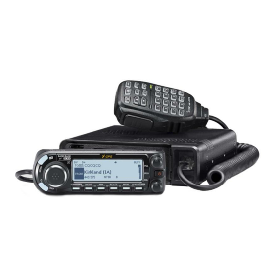
Icom ID-4100A Basic Manual
Dual band transceivers
Hide thumbs
Also See for ID-4100A:
- Manual (36 pages) ,
- Advanced manual (273 pages) ,
- Service manual (46 pages)
Table of Contents
Advertisement
Quick Links
BASIC MANUAL
DUAL BAND TRANSCEIVER
ID-4100A
ID-4100E
This device complies with Part 15 of the FCC rules. Operation is
subject to the following two conditions: (1) This device may not cause
harmful interference, and (2) this device must accept any interference
received, including interference that may cause undesired operation.
WARNING: MODIFICATION OF THIS DEVICE TO RECEIVE CEL-
LULAR RADIOTELEPHONE SERVICE SIGNALS IS PROHIBITED
UNDER FCC RULES AND FEDERAL LAW.
Advertisement
Chapters
Table of Contents

Subscribe to Our Youtube Channel
Related Manuals for Icom ID-4100A


Summary of Contents for Icom ID-4100A
- Page 1 BASIC MANUAL DUAL BAND TRANSCEIVER ID-4100A ID-4100E This device complies with Part 15 of the FCC rules. Operation is subject to the following two conditions: (1) This device may not cause harmful interference, and (2) this device must accept any interference received, including interference that may cause undesired operation.
-
Page 2: Important
Thank you for choosing this Icom product. This product is EXPLICIT DEFINITIONS designed and built with Icom’ s state of the art technology and craftsmanship. With proper care, this product should provide you with years of trouble-free operation. WORD DEFINITION... -
Page 3: About The Construction Of The Manual
Enter ‘ID-4100’ into the Search box in the site. • If necessary, you can see a glossary of HAM radio terms that can be downloaded from the Icom website. • To read the guide or manual, Adobe Acrobat Reader is required. If you have not installed it, please download the Adobe Acrobat Reader from Adobe Systems Incorporated’s website. -
Page 4: Options
USB type earthquakes, storms, floods, lightning, other natural data cable OPC-478UC USB type disasters, disturbances, riots, war, or radioactive cloning cable contamination. • The use of Icom transceivers with any equipment that is not manufactured or approved by Icom. BASIC MANUAL... -
Page 5: Table Of Contents
TABLE OF CONTENTS BY TOPIC Controller MENU screen/Quick Menu Attaching/Installing ............1, 2 Quick Menu window ............20 Front panel ................9 MENU screen description ..........27 Display ................11 Menu item list ..............63 Power key ................19 Details of the MENU screen .......AM* (sec. 9) Microphone Memory channel Connecting ................ -
Page 6: Precautions
PRECAUTIONS R DANGER HIGH VOLTAGE! NEVER touch the antenna R WARNING! NEVER connect the transceiver to an AC connector during transmission. This may result in an outlet. This may pose a fire hazard or result in an electric electrical shock or burn. shock. - Page 7 R WARNING! NEVER operate the transceiver if it emits an CAUTION: DO NOT use non-Icom microphones. Other manufacturer’s microphones have different pin assignments, abnormal odor, sound or smoke. Immediately turn OFF the transceiver power and remove the power cable. Contact and may damage the transceiver.
-
Page 8: Important Notes
IMPORTANT NOTES D When using the GPS receiver D About GPS antenna • GPS signals cannot pass through metal objects. When This transceiver’s GPS antenna is located at the top back using the transceiver inside a vehicle, you may not receive of the controller. - Page 9 Adobe Systems Incorporated in the United States and/or other countries. The Bluetooth word mark and logos are registered trademarks owned by the Bluetooth SIG, Inc. and any use of such marks by Icom Inc. is under license. Other trademarks and trade names are those of their respective owners.
-
Page 10: Définitions Explicites
PRÉCAUTIONS DÉFINITIONS EXPLICITES R DANGER TENSION À HAUTES RF ! NE JAMAIS DÉFINITION toucher l'antenne en cours d'émission ou de réglage d'accord. Au risque de provoquer un choc electrique ou des Risque d'accident mortel, de brulures. RDANGER ! blessures corporelles graves ou d'explosion. - Page 11 24 V. Cela pourrait causer un incendie ou endommager l'émetteur-récepteur. fumée ou un bruit anormal. Contactez votre revendeur ou distributeur Icom pour obtenir des conseils. R AVERTISSEMENT ! NE JAMAIS inverser la polarité lors de la connexion du câble d’alimentation CC à une source R AVERTISSEMENT ! NE JAMAIS placer jamais d’alimentation.
- Page 12 à l’ID-4100A/E peut endommager l’émetteur- MISE EN GARDE: Tout changement ou modification, récepteur. non expressément approuvé par Icom Inc., peut annuler NE PAS appuyer sur la touche PTT sans intention réelle l'autorisation de l'utilisateur à utiliser cet appareil d’émettre.
-
Page 13: Information Fcc
être déterminé en éteignant et en allumant l'équipement, l'utilisateur est invité à essayer de corriger l'interférence en Icom n'est pas responsable de la destruction ou prenant une ou plusieurs des mesures ci-après: des dommages sur l'émetteur-récepteur Icom, si le •... - Page 14 TABLE OF CONTENTS 2 PANEL DESCRIPTION ........9–18 IMPORTANT ................. i EXPLICIT DEFINITIONS ............i ■ Controller — Front panel ..........9 SUPPLIED ACCESSORIES ..........i ■ Controller — Display ..........11 ABOUT THE CONSTRUCTION OF THE MANUAL ..... ii ■ Main unit — Front panel ...........14 OPTIONS ................iii ■...
- Page 15 5 MEMORY OPERATION ........ 41–42 10 SPECIFICATIONS ........57–58 ■ Entering Memory channels ........41 11 INFORMATION ..........59–60 ■ Checking the Memory contents ........41 ■ Country code list ............59 ■ Selecting a Memory channel ........42 ■ Disposal ..............59 6 SCAN OPERATION ........43–46 ■...
-
Page 16: Controller
INSTALLATION AND CONNECTIONS ■ Attaching the controller D When attaching to the main unit D When connecting to the main unit Attaching: Connect the controller to the main unit with the supplied Slide the controller in the direction of the arrow until the control cable. -
Page 17: Installing The Controller
INSTALLATION AND CONNECTIONS ■ Installing the controller 3. Slide the MBA-8’s guide down over the MBF-1’s locking head, as shown below. L Be sure the locking head fits into the slot at the top of the D When installing into your vehicle guide. -
Page 18: Microphone Connecting
INSTALLATION AND CONNECTIONS ■ Connecting a microphone ■ Installing the controller (Continued) D Attaching to a flat surface Plug in the microphone into the microphone jack on the You can install the controller on a flat surface with the optional MBA-8 . -
Page 19: Installing In A Vehicle
Battery Screw cable (12 V) 25º More than 100 mm (3.9 inches) height (recommended) Flat washer Spring washer When using self- NOTE: Contact your car dealer or Icom dealer for advice tapping screws for installing in a vehicle. BASIC MANUAL... -
Page 20: Installing An Antenna
INSTALLATION AND CONNECTIONS ■ Installing an antenna D About the antenna To obtain maximum performance from the transceiver, select a high-quality antenna and mount it in a good location. For radio communications, the antenna is of critically importance, along with output power and receiver sensitivity. Antenna location Select a well-matched 50 Ω... -
Page 21: Connecting To A Battery
INSTALLATION AND CONNECTIONS ■ Connecting to a battery R WARNING! CONNECTING TO A • NEVER remove the fuses from the cable connecting the VEHICLE BATTERY transceiver to a power source, especially a car battery. Red line: + • NEVER connect the transceiver directly to a 24 V battery. Black line: _ The transceiver must be connected to a 24 V battery through the DC-DC converter. -
Page 22: Bluetooth Installing The Ut-137
INSTALLATION AND CONNECTIONS ■ Installing the UT-137 3. Place one end the UT-137 under the edge of the front panel, with the connector facing down. When you install the optional UT-137 Bluetooth ® unit in Front panel UT-137 the transceiver, you can communicate with other Bluetooth device. -
Page 23: Electromagnetic Interference
INSTALLATION AND CONNECTIONS ■ Electromagnetic Interference When you use a Bluetooth device, pay attention to the following: Bluetooth devices operate on the 2.4 GHz band. The 2.4 GHz band is also used by other devices, such as Wireless LAN products, microwave ovens, RFID systems, amateur radio stations, and so on. -
Page 24: Front Panel
PANEL DESCRIPTION ■ Controller — Front panel Display (p. 11) !1 !2 3 BACK • DR KEY []/[DR] 1 MENU • LOCK KEY [MENU]/[ • Push to toggle between “TO” and “FROM” on the DR • Push to display the MENU screen. (p. 28) screen. - Page 25 PANEL DESCRIPTION 4 BAND/BANK • ENTER • SCAN KEY 9 MONITOR KEY [MONI] [BAND/BANK]/[ï]/[SCAN] Push to turn the Monitor function ON or OFF. (p. 19) • In the VFO mode, push to enter the Band Select mode. 10 QUICK MENU • MUTE KEY [QUICK]/[MUTE] •...
-
Page 26: Display
PANEL DESCRIPTION ■ Controller — Display !5 !3 !6 !4 (Example) 1 MODE ICONS 7 S/RF METER • Displays the relative signal strength of the receive Displays the selected operating mode. signal. 2 FREQUENCY READOUT • Displays the output power level of the transmit signal. Displays the operating frequency. - Page 27 PANEL DESCRIPTION 11 AUTO POWER OFF ICON 18 WEATHER ALERT ICON Displayed when the Auto power OFF function is ON. Displayed when the Weather Alert function is ON. (Only the USA version transceiver) 12 GPS ICON 19 PRIORITY ICON • Displays the status of the GPS receiver. (p. 51) •...
- Page 28 PANEL DESCRIPTION ■ Controller — Display (Continued) (Example) @0 TONE ICONS (Continued) • TONE(T)/TSQL(R) (“T-TSQL” is displayed, “T” blinks.): • TONE(T)/DTCS(R) (“T-DTCS” is displayed, “T” blinks.): When you transmit, the selected subaudible When you transmit, the selected subaudible tone is superimposed on your normal signal.
-
Page 29: Front/Rear Panel
PANEL DESCRIPTION ■ Main unit — Front panel D Microphone connector information Front panel view NAME DESCRIPTION SPECIFICATIONS +8 V DC output Maximum 10 mA 1 microSD CARD SLOT [micro SD] (p. 48) UP: Ground Insert a microSD card (user supplied). MIC U/D Frequency Up/Down DN: Ground 2 CONTROLLER CONNECTOR (p. -
Page 30: Main Unit - Rear Panel
PANEL DESCRIPTION ■ Main unit — Rear panel 1 ANTENNA CONNECTOR 4 EXTERNAL SPEAKER JACK Connect to a 50 Ω impedance antenna with a PL-259 Connect to an 8 Ω external speaker. connector. 3.5 mm (0.13 in) (d) L The transceiver has a built-in duplexer, so you can use a 144 5 DC POWER SOCKET [DC 13.8V] and 430 MHz dual-band antenna without needing an external Connect to a 13.8 V DC power source through the... -
Page 31: Microphone (Hm-207S)
PANEL DESCRIPTION ■ Microphone (HM-207S) 3 [PTT] SWITCH With the HM-207S, you can input numbers for frequency or Hold down to transmit, release to receive. Memory channel setting, and easily adjust the audio volume or squelch level. NOTE: To maximize the readability of your signal, hold the microphone 5 to 10 cm (2 to 4 inches) from your mouth, then speak at your normal voice level. - Page 32 PANEL DESCRIPTION ■ Microphone (HM-207S) (Continued) 12 [VOL√/B] KEY • Push to decrease the audio output level. • In the DTMF Code Entry mode, push to input ‘B.’ 13 [SQL∫/C] KEY • Push to increase the squelch level. • In the DTMF Code Entry mode, push to input ‘C.’ Mic element 14 [SQL√/D] KEY •...
- Page 33 PANEL DESCRIPTION D Setting the frequency and Memory channels Example of frequency setting: z First, push [VFO/MR] to select the VFO mode. To enter the frequency 435.680 MHz: z Push [4], [3], [5], [6], [8], [0], then [ENT]. To change 435.680 MHz to 435.540 MHz: z Push [•], [5], [4], [0], then [ENT].
-
Page 34: Power Key
BASIC OPERATION ■ Turning ON the transceiver ■ Setting audio volume and squelch level Hold down [ ] for 1 second to turn ON the transceiver. • A beep sounds. Rotate [VOL] to adjust the audio level. • After the opening message and power source voltage are 2. -
Page 35: Quick Menu Window
BASIC OPERATION ■ Quick Menu window D Quick Menu window operation You can open the Quick Menu window by pushing [QUICK]. In the window, the selectable items differ, depending on [ï] the operating mode or function. The items listed below are •... -
Page 36: Selecting The Mode
BASIC OPERATION ■ Selecting the Mode D VFO mode D Weather channel mode You use the VFO mode to set the operating frequency. (Selectable in only the USA version transceivers) You can use the Weather channel mode to hear weather D Memory mode broadcasts from the National Oceanographic and You use the Memory mode to operate on Memory channels. -
Page 37: Selecting The Operating Band
BASIC OPERATION ■ Selecting the operating band ■ Selecting the operating mode The transceiver can receive on the AIR, 144 MHz, 230 MHz, The transceiver has a total of 5 operating modes, AM, AM-N, 300 MHz, and 430 MHz bands.* FM, FM-N, and DV. -
Page 38: Setting A Frequency
BASIC OPERATION ■ Setting a frequency D Selecting a tuning step D Selecting the 1 MHz tuning If you select the operating frequency by rotating [DIAL] You can change the operating frequency in ‘MHz’ steps for in the VFO mode, the frequency changes in the selected quick tuning. -
Page 39: Lock Function
BASIC OPERATION ■ Lock function ■ DR function You can use the Lock function to prevent accidental The DR (D-STAR Repeater) function is for D-STAR repeater frequency changes and unnecessary function access. operation. This function enables you to easily select the preset repeaters and UR call signs by rotating [DIAL]. -
Page 40: Speech Function
BASIC OPERATION ■ Speech function ■ Home Channel function The Speech function audibly announces information You can set an often-used frequency, Memory channel, or after pushing [SPCH]. Also, you can set various Speech repeater as the Home channel in each mode (VFO/Memory/ functions, such as the DIAL Speech function or Mode DR). -
Page 41: Transmitting
BASIC OPERATION ■ Transmitting D Transmitting on an Amateur band Before transmitting, monitor the operating frequency to make sure transmitting won’t cause interference to other stations on the same frequency. CAUTION: DO NOT transmit without an antenna. This may damage the transceiver. NOTE: You can transmit on only the amateur band frequencies. -
Page 42: Menu Screen Description
MENU SCREEN ■ MENU screen description ■ Selecting a Menu item The MENU screen is displayed after pushing [MENU]. D MENU screen operation You can use the MENU screen to set infrequently changed values or function settings. [MENU] Switches between the MENU See the following pages for details of each set screen. -
Page 43: Menu Screen
MENU SCREEN ■ Menu items and their details This topic describes the Menu items and their details. D Selecting a Menu item See the Advanced manual for details. (Section 9) Example: Set the “Auto Power OFF” item to “30 min.” Time Set >... - Page 44 MENU SCREEN ■ Menu items and their details (Continued) Voice Memo Manage Memory Set the TX/RX voice recording options. Manages for your Memory or Call channel data. QSO Recorder Memory CH Set QSO recorder options. <<REC Start>>* Manages for the Memory channels. Call CH Starts recording the received signal audio.
- Page 45 MENU SCREEN D-PRS (DV-A) (GPS > GPS TX Mode) Voice TX Set D-PRS options. Set microphone voice recording options. Unproto Address Record* Enters an unproto address, or keeps the default. Starts recording the microphone audio. TX Format TX Set Position Repeat Time Symbol Sets the repeat interval.
- Page 46 MENU SCREEN ■ Menu items and their details (Continued) Directivity (GPS > GPS TX Mode > TX Format > Object) Object (GPS > GPS TX Mode > TX Format) Selects an Object’s antenna directivity to transmit. SSID Set Object data such as an earthquake information, satellite track information, and so on, to transmit along with the Selects an Object’s APRS ®...
- Page 47 MENU SCREEN Height (GPS > GPS TX Mode > TX Format > Item) GPS Memory Selects an Item’s height to transmit. Shows the GPS memory contents. Gain GPS Alarm Selects an Item’s antenna gain to transmit. Set GPS alarm options. Directivity Alarm Select Selects an Item’s antenna directivity to transmit.
- Page 48 MENU SCREEN ■ Menu items and their details (Continued) RX Bass (DV Set > Tone Control) Sets the DV mode received audio bass filter level to Cut, Normal RX History or Boost. Displays the received call history in the DV mode. RX Treble RX01: Sets the DV mode received audio treble filter level to Cut,...
- Page 49 MENU SCREEN TX Delay (PTT) (DV Set > DV Fast Data) DIAL SPEECH Set the TX delay time after releasing [PTT] when the “DV Data Turns the Dial Speech function ON or OFF. TX” is set to “PTT” and data is sent in the DV Fast data mode. MODE SPEECH Digital Monitor Turns the Operating Mode Speech function ON or OFF.
- Page 50 MENU SCREEN ■ Menu items and their details (Continued) Up/Down MIC Key CSV Format (QSO/RX Log) Selects the key function for [UP] or [DN] on the optional hand microphone. Set CSV format options. During RX/Standby Separator/Decimal Selects the key function to be used while receiving or in the Selects the separator and the decimal character for the CSV standby mode.
- Page 51 MENU SCREEN CI-V Address (Function > CI-V) Night Time Start Sets the transceiver’s unique CI-V hexadecimal address code. Sets the start time for nighttime operation. CI-V Baud Rate Night Time End Sets the CI-V code transfer speed. Sets the end time for nighttime operation. CI-V Transceive Auto Dimmer Setting Turns the CI-V Transceive function ON or OFF.
- Page 52 MENU SCREEN ■ Menu items and their details (Continued) Rainfall Selects the units to display the rainfall. RX Position Display Timer (Display) Wind Speed Sets the RX position data display time period. Selects the units to display the wind speed. Reply Position Display Display Language Selects whether or not to display the caller’s position data in a...
- Page 53 MENU SCREEN Time Set File selection Saves the settings in a selected file. Sets the Time options. Import/Export Date/Time Import or export the CSV format file. DATE Import Sets the current date. Selects to import the Your call sign, Repeater list, or GPS TIME memory data in the CSV format file.
- Page 54 Sets the VOX Time-Out Timer to prevent an accidental Search Data Device prolonged transmission. Icom Headset Searches for a Bluetooth data device. Sets to use the optional Icom Bluetooth headset (VS-3). Pairing list Power Save Displays the paired device. <<Pairing Reception>>...
- Page 55 MENU SCREEN Custom Key (Bluetooth Set > Headset Set > Icom Headset) Selects the key function of the custom key ([PLAY]/[FWD]/ [RWD]). Data Device Set Sets the data device options. Serialport Function Selects to transmit or receive the CI-V command or the DV data.
-
Page 56: Memory Channel Operation
MEMORY OPERATION ■ Entering Memory channels ■ Checking the Memory contents The transceiver has a total of 1000 Memory channels to You can check the Memory contents on the MEMORY LIST save often-used frequencies. screen. In the Memory mode, you can quickly select the saved Example: Checking the contents of Memory channel 5. -
Page 57: Selecting A Memory Channel
MEMORY OPERATION ■ Selecting a Memory channel In the Memory mode, you can select the Memory channels by rotating [DIAL]. Push [V/M] several times until you enter the Memory mode. Displayed L Pushing [V/M] toggles between the VFO and Memory modes. -
Page 58: Scan Operation
SCAN OPERATION Scanning is a versatile function that can automatically D Scan type search for signals. A scan makes it easier to locate stations The VFO mode scan has 6 scan types. to contact or listen to, or to skip unwanted channels or •... - Page 59 SCAN OPERATION D Setting the skip frequencies You can set unnecessary frequencies as a Skip channel TIP: Once frequencies are set as a Skip channel, these (PSKIP) to be skipped during a scan. The Skip function frequencies are skipped until clearing the skip setting. To speeds up a scan.
-
Page 60: Memory Scan
SCAN OPERATION ■ Memory scan D Scan type NOTE: Two or more memory channels, which are not set The Memory mode scan has 5 scan types. as Skip channels, must be entered to start a Memory scan. • ALL: Full scan Push [V/M] several times until you enter the Memory •... -
Page 61: Setting And Clearing A Skip Channel
SCAN OPERATION ■ Setting and clearing a Skip channel You can set or clear a Skip channel setting. The channels that are set as a Skip channel are skipped during a scan. Push [V/M] several times until you enter the Memory mode. -
Page 62: Recording A Qso Onto A Microsd Card
PC. TIP: Saving the factory default data is recommended. To • Icom will not be responsible for any damage caused by save data, insert the card into the transceiver’s slot, then data corruption of a microSD card. -
Page 63: Inserting The Microsd Card
RECORDING A QSO ONTO A microSD CARD ■ Inserting the microSD card NOTE: Before inserting, be sure to check the card D Formatting the microSD card direction. If the card is forcibly or inversely inserted, it will Before using a microSD card, format it to be used with the damage the card and/or the slot. -
Page 64: Removing The Microsd Card
RECORDING A QSO ONTO A microSD CARD ■ Removing the microSD card D Removing the microSD card while the NOTE: DO NOT remove the card from the transceiver while the card is being accessed. Otherwise, the card data transceiver’s power is ON may be corrupted or deleted. -
Page 65: Recording A Qso Audio
RECORDING A QSO ONTO A microSD CARD ■ Recording a QSO audio ■ Playing recorded audio NOTE: Once the voice recording starts, it will continue Voice Memo > QSO Recorder > Play Files until you stop recording, even if you turn OFF the Push [MENU]. -
Page 66: Gps Operation
GPS OPERATION ■ Checking your GPS position NOTE: The built-in GPS receiver cannot calculate its position if it cannot receive signals from the GPS satellites. Refer to page vii for details. You can check your current position. If you transmit while displaying the GPS position screen, the ■... - Page 67 GPS OPERATION 3. Rotate [DIAL]. Push []. • Selects the page. • Returns to the standby screen. My position About the GPS POSITION screen screen Compass direction Longitude top is North. Latitude Altitude Speed Received position Your course screen 1 heading is West Received...
-
Page 68: Maintenance
MAINTENANCE ■ Resetting Occasionally, erroneous information will be displayed when, D Partial Reset for example, first applying power. This may be caused Others > Reset > Partial Reset externally by static electricity or by other factors. If this problem occurs, turn OFF the transceiver. After waiting a Push [MENU]. -
Page 69: Fuse Replacement
NOTE: When the power supply voltage is high, the transceiver automatically displays “Over Voltage,” and then sounds a warning beep. In this case, the transceiver may be damaged. In that case, contact your nearest Icom R WARNING! Dealer or Service Center. -
Page 70: Troubleshooting
The following chart is designed to help you correct problems which are not equipment malfunctions. If you are unable to locate the cause of a problem, or solve it through the use of this chart, contact your nearest Icom Dealer or Service Center. - Page 71 MAINTENANCE PROBLEM POSSIBLE CAUSE SOLUTION REF. Transmitting is • Duplex function are ON, and the transmit • Turn OFF the Duplex function. impossible, or the and receive frequencies are different. sec. 8 transmit power level • The transmit power level is set to LOW or •...
-
Page 72: Specifications
SPECIFICATIONS D General • Frequency coverage: • No. of repeater lists: 1500 Receive • No. of GPS memory: 118 ~ 174 MHz (Guaranteed only 144 ~ 146 MHz) • Antenna impedance: 50 Ω (SO-239) 230 ~ 550 MHz (Guaranteed only 430 ~ 440 MHz) •... - Page 73 ≤ –60 dBc ≤ 1.8 μV (322.000 to 374.995 MHz) • Output power: High 50 W, Mid 15 W, * The ID-4100A/E can receive the AM-N mode in only the Low 5 W 118.000 to 136.991 MHz band. • Squelch sensitivity: ≤...
-
Page 74: Information
INFORMATION ■ Country code list ■ Disposal • ISO 3166-1 The crossed-out wheeled-bin symbol on your product, literature, or packaging reminds you Country Codes Country Codes that in the European Union, all electrical and Austria Liechtenstein electronic products, batteries, and accumulators Belgium Lithuania (rechargeable batteries) must be taken to... -
Page 75: Fcc Information
• Consult the dealer or an experienced radio/TV technician for help. CAUTION: Changes or modifications to this device, not expressly approved by Icom Inc., could void your authority to operate this device under FCC regulations. BASIC MANUAL... -
Page 76: Index
INDEX Accessories ..................i GPS operation ................51 Antenna Checking your GPS position ............51 Installing ..................5 Confirming the GPS signal receiving .......... 51 Internal duplexer ................5 Audio volume level setting ............. 19 Home Channel function ..............25 Call channel mode selecting............21 Installation .................. - Page 77 INDEX Microphone (HM-207S) ..............16 Connecting ................... 3 Scan operation ................43 Microphone connector information ..........14 Memory scan ................45 microSD card ................. 47 Setting and clearing a Skip channel ........... 46 Formatting .................. 48 Setting the skip frequencies ............44 Inserting ..................
-
Page 78: Menu Item List
MENU ITEM LIST The first tree level of each Menu category are listed below. DUP/TONE... Offset Freq DV Memory Your Call Sign Repeater Tone Repeater List TSQL Freq My Station My Call Sign Tone Burst TX Message DTCS Code DV Set Tone Control DTCS Polarity Auto Reply... - Page 79 MENU ITEM LIST Function Squelch/ATT Select Sounds Beep Level Squelch Delay Key-Touch Beep Fan Control Home CH Beep Dial Speed-UP Band Edge Beep Auto Repeater Scan Stop Beep Remote MIC Key Standby Beep Up/Down MIC Key Scope AF Output One-Touch PTT(Remote MIC) Time Set Date/Time PTT Lock...
- Page 80 ■ ■ ■ ■ ■ IT ■ ■ ■ ■ ■ ■ ■ ■ ■ ■ ■ ■ ■ ■ ■ ■ ■ ■ ■ ■ A-7367D-1EX-q Printed in Japan 1-1-32 Kamiminami, Hirano-ku, Osaka 547-0003, Japan © 2017 Icom Inc.
Need help?
Do you have a question about the ID-4100A and is the answer not in the manual?
Questions and answers