Siemens RUGGEDCOM RSG2100 Installation Manual
Hide thumbs
Also See for RUGGEDCOM RSG2100:
- Installation manual (46 pages) ,
- Installation manual (56 pages) ,
- Installation manual (52 pages)

Related Manuals for Siemens RUGGEDCOM RSG2100


Summary of Contents for Siemens RUGGEDCOM RSG2100
- Page 1 Preface Introduction Installing Device RUGGEDCOM RSG2100 Communication Ports Technical Specifications Dimension Drawings Installation Guide Certification 06/2017 RC1040-EN-10...
-
Page 2: Security Information
Warranty Siemens warrants this product for a period of five (5) years from the date of purchase, conditional upon the return to factory for maintenance during the warranty term. This product contains no user-serviceable parts. Attempted service by unauthorized personnel shall render all warranties null and void. - Page 3 RUGGEDCOM RSG2100 Installation Guide Contacting Siemens Address Telephone E-mail Siemens Canada Ltd Toll-free: 1 888 264 0006 ruggedcom.info.i-ia@siemens.com Industry Sector Tel: +1 905 856 5288 300 Applewood Crescent Fax: +1 905 856 1995 Concord, Ontario www.siemens.com/ruggedcom Canada, L4K 5C7...
- Page 4 RUGGEDCOM RSG2100 Installation Guide...
-
Page 5: Table Of Contents
RUGGEDCOM RSG2100 Installation Guide Table of Contents Table of Contents Preface ......................Alerts ..............................vii Related Documents ..........................viii Accessing Documentation ........................viii Training ............................viii Customer Support ..........................viii Chapter 1 Introduction ..................... 1.1 Feature Highlights ........................1 1.2 Description ........................... 2 Chapter 2 Installing Device .................... - Page 6 RUGGEDCOM RSG2100 Table of Contents Installation Guide 3.3 SFP Transceivers ......................... 24 3.4 GBIC Optic Ethernet Ports ......................25 3.4.1 Installing a GBIC Optical Port .................... 25 3.4.2 Removing a GBIC Optical Port ................... 27 Chapter 4 Technical Specifications .................. 4.1 Power Supply Specifications ......................29 4.2 Failsafe Relay Specifications ......................
-
Page 7: Preface
Installation Guide Preface Preface This guide describes the RUGGEDCOM RSG2100. It describes the major features of the device, installation, commissioning and important technical specifications. It is intended for use by network technical support personnel who are responsible for the installation, commissioning and maintenance of the device. -
Page 8: Related Documents
Mobile App Install the Industry Online Support app by Siemens AG on any Android, Apple iOS or Windows mobile device and be able to: • Access Siemens' extensive library of support documentation, including FAQs and manuals • Submit SRs or check on the status of an existing SR •... -
Page 9: Introduction
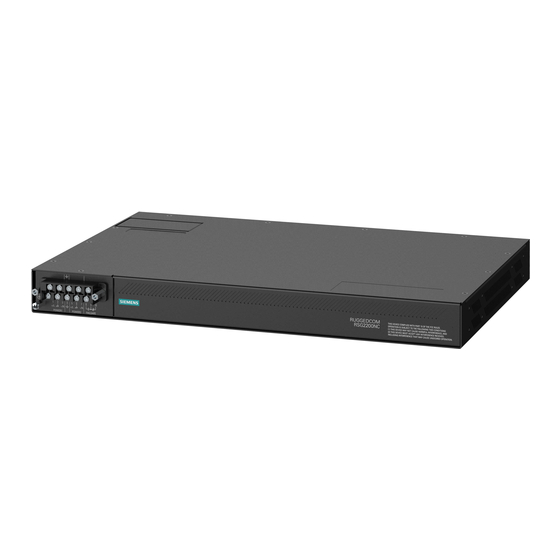
RSG2100 highly versatile for any application and can support multiple fiber connectors (ST, MTRJ, LC, SC) without loss of port density. The RUGGEDCOM RSG2100 is packaged in a rugged galvanized steel enclosure with industrial grade DIN, panel, or 48 cm (19 in) rack-mount mounting options. -
Page 10: Description
Section 1.2 Description The RUGGEDCOM RSG2100 features various ports, controls and indicator LEDs on the display panel for connecting, configuring and troubleshooting the device. The display panel can be located on the rear, front or top of the device, depending on the mounting configuration. - Page 11 RUGGEDCOM RSG2100 Chapter 1 Installation Guide Introduction Display Mode Indicator LEDs The display mode indicator LEDs indicate the current display mode for the port status indicator LEDs (i.e. Status, Duplex or Speed). Mode button The Mode button sets the display mode for the port status indicator LEDs (i.e. Status, Duplex or Speed).
- Page 12 Chapter 1 RUGGEDCOM RSG2100 Introduction Installation Guide Description...
-
Page 13: Installing Device
This product contains no user-serviceable parts. Attempted service by unauthorized personnel shall render all warranties null and void. Changes or modifications not expressly approved by Siemens Canada Ltd could invalidate specifications, test results, and agency approvals, and void the user's authority to operate the equipment. -
Page 14: General Procedure
Connect power to the device and ground the device to safety Earth. Connect the device to the network. Configure the device. Section 2.2 Required Tools and Materials The following tools and materials are required to install the RUGGEDCOM RSG2100: Tools/Materials Purpose AC power cord (16 AWG) For connecting power to the device. -
Page 15: Cabling Recommendations
Siemens also does not recommend using copper Ethernet ports to interface with devices in the field across distances that could produce high levels of ground potential rise (i.e. greater than 2500 V), during line-to-ground fault conditions. -
Page 16: Installing The Device In Hazardous Locations
Installing the Device in Hazardous Locations The RUGGEDCOM RSG2100 is designed to comply with the safety standards for Class I, Division 2, Zone 2 hazardous locations where concentrations of flammable gases, vapors or liquids may be present, as opposed to normal operating environments. -
Page 17: Mounting The Device
Section 2.5.1 Mounting the Device to a Rack The RUGGEDCOM RSG2100 can be secured to a standard 48 cm (19 in) rack using separately purchased rack mount adapters. The adapters can be installed at the front or rear of the chassis. - Page 18 Chapter 2 RUGGEDCOM RSG2100 Installing Device Installation Guide CAUTION! Vibration hazard – risk of damage to the device. In high-vibration or seismically active locations, always install four rack mount adapters (two at the front of the chassis and two at the rear).
-
Page 19: Mounting The Device On A Din Rail
Mounting the Device on a DIN Rail For DIN rail installations, the RUGGEDCOM RSG2100 can be equipped with panel/DIN rail adapters pre-installed on each side of the chassis. The adapters allow the device to be slid onto a standard 35 mm (1.4 in) DIN rail. -
Page 20: Connecting The Failsafe Alarm Relay
Control of the failsafe relay output is configurable through ROS. One common application for this relay is to signal an alarm if a power failure occurs. For more information, refer to the ROS User Guide for the RUGGEDCOM RSG2100. The following shows the proper relay connections. -
Page 21: Connecting Power
The RUGGEDCOM RSG2100 supports a single or dual redundant AC and/or DC power supplies. The RUGGEDCOM RSG2100 can be equipped with either a screw-type or pluggable terminal block, which provides power to both power supplies . The screw-type terminal block is installed using Phillips screws and compression plates, allowing either bare wire connections or crimped terminal lugs. -
Page 22: Connecting Ac Or Dc Power
Chapter 2 RUGGEDCOM RSG2100 Installing Device Installation Guide • Section 2.7.2, “Wiring Examples” Section 2.7.1 Connecting AC or DC Power To connect a single high AC, high DC or low DC power supply to the device, do the following: CAUTION! Electrical hazard – risk of damage to equipment. Before testing the dielectric strength (HIPOT) in the field, remove the metal jumper. - Page 23 RUGGEDCOM RSG2100 Chapter 2 Installation Guide Installing Device Figure 7: Terminal Block Wiring 1. Screw-Type Terminal Block 2. Pluggable Terminal Block 3. Jumper 4. Positive/Live (+/L) Terminal 5. Negative/Neutral (-/N) Terminal (-/N) 6. Surge Ground Terminal 7. Chassis Ground Terminal Connect the negative wire from the power source to the negative/neutral (-/N) terminal on the terminal block.
-
Page 24: Wiring Examples
Chapter 2 RUGGEDCOM RSG2100 Installing Device Installation Guide Section 2.7.2 Wiring Examples The following illustrate how to connect power to single and dual power supplies. Figure 9: Single AC Power Supply Figure 10: Single DC Power Supply Wiring Examples... - Page 25 RUGGEDCOM RSG2100 Chapter 2 Installation Guide Installing Device Figure 11: Dual AC Power Supply Figure 12: Dual DC Power Supply Wiring Examples...
-
Page 26: Connecting To The Device
Connecting to the Device The following describes the various methods for accessing the ROS console and Web interfaces on the device. For more detailed instructions, refer to the RUGGEDCOM ROS User Guide for the RUGGEDCOM RSG2100. RS232 Console Port Connect a workstation directly to the RS232 console port to access the boot-time control and ROS interfaces. The console port provides access to ROS's console and Web interfaces. -
Page 27: Configuring The Device
RUGGEDCOM RSG2100 Chapter 2 Installation Guide Installing Device Name Description Comment RJ45 Male Female Receive Data (to DTE) Transmit Data (from DTE) Clear to Send Read to Send Ring Indicator The DSR, DCD and DTR pins are connected together internally. - Page 28 Chapter 2 RUGGEDCOM RSG2100 Installing Device Installation Guide Configuring the Device...
-
Page 29: Communication Ports
Chapter 3 Installation Guide Communication Ports Communication Ports The RUGGEDCOM RSG2100 can be equipped with various types of communication ports to enhance its abilities and performance. Module Assignment Figure 15: Module Assignment Each type of module has a specific location in the RUGGEDCOM RSG2100 chassis: •... -
Page 30: Copper Ethernet Ports
Section 3.1 Copper Ethernet Ports The RUGGEDCOM RSG2100 supports several 10/100/1000Base-TX Ethernet ports that allow connection to standard Category 5 (CAT-5) unshielded twisted-pair (UTP) cables with either RJ45 or Micro-D male connectors. The RJ45 and Micro-D connectors are directly connected to the chassis ground on the device and can accept CAT-5 shielded twisted-pair (STP) cables. -
Page 31: Specifications
RUGGEDCOM RSG2100 Chapter 3 Installation Guide Communication Ports Name Description 10/100Base-TX 1000Base-TX BI_DB+ Transmit Data+ or Bi-Directional Pair B+ Reserved (Do BI_DC+ Transmit Data+ Not Connect) or Bi-Directional Pair C+ Reserved (Do BI_DC- Receive Not Connect) Data- or Bi- Directional Pair C-... -
Page 32: Fiber Optic Ethernet Ports
The RUGGEDCOM RSG2100 features two Small Form-Factor Pluggable (SFP) transceiver sockets, which are compatible with a wide array of SFP transceivers available from Siemens. The following SFP transceivers are compatible with the RUGGEDCOM RSG2100. For more information, including installation/removal instructions and ordering information, refer to the RUGGEDCOM SFP Transceiver Catalog [https://support.industry.siemens.com/cs/ca/en/view/109482309] . -
Page 33: Gbic Optic Ethernet Ports
GBIC optical ports when an explosive atmosphere is present. CAUTION! Electrical hazard – risk of damage to equipment. Use only components certified by Siemens with RUGGEDCOM products. Damage to the module and device may occur if compatibility and reliability have not been properly assessed. - Page 34 IMPORTANT! Only install GBIC optical ports that are compatible with the RUGGEDCOM RSG2100. Make sure all potential electrostatic build-up has been properly discharged to prevent electrostatic discharges (ESD). This can be accomplished by wearing an ESD-preventive wrist strap connected to either the chassis ground connector or a bare metal surface on the router/switch.
-
Page 35: Removing A Gbic Optical Port
RUGGEDCOM RSG2100 Chapter 3 Installation Guide Communication Ports Section 3.4.2 Removing a GBIC Optical Port To remove an GBIC optical port, do the following: WARNING! Explosion hazard – risk of serious personal injury and/or equipment damage. Do not install or remove GBIC optical ports when an explosive atmosphere is present. - Page 36 Chapter 3 RUGGEDCOM RSG2100 Communication Ports Installation Guide Removing a GBIC Optical Port...
-
Page 37: Technical Specifications
Section 4.7, “Mechanical Specifications” Section 4.1 Power Supply Specifications The RUGGEDCOM RSG2100 can be equipped with the following power supplies: CAUTION! Electrical hazard – risk of damage to the device. Disconnect the device from the power supply if power input is above or below the specified input range. -
Page 38: Failsafe Relay Specifications
Chapter 4 RUGGEDCOM RSG2100 Technical Specifications Installation Guide Non-Hazardous Environments Input Range Maximum Power Power Supply Type Internal Fuse Rating Consumption Minimum Maximum 24 VDC 10 VDC 36 VDC 6.3 A(F) 48 VDC 36 VDC 72 VDC 3.15 A(T) 28 W... -
Page 39: Copper Ethernet Port Specifications
NOTE • Maximum segment length is greatly dependent on factors such as fiber quality, and the number of patches and splices. Consult a Siemens sales associate when determining maximum segment distances. • All optical power numbers are listed as dBm averages. -
Page 40: Fl Ethernet Optical Specifications
Chapter 4 RUGGEDCOM RSG2100 Technical Specifications Installation Guide 10FL Ethernet Optical Specifications Power Connector Cable Tx min Tx max Distance Mode Tx λ (nm) Sensitivity Saturation Budget Type Type (µm) (dBm) (dBm) (typ.) (km) (dBm) (dBm) (dB) 62.5/125 -11.2 50/125 -19.8... -
Page 41: Operating Environment
All optical power numbers are listed as dBm averages. Typical distance. The maximum segment length is greatly dependent on factors such as fiber quality, and the number of patches and splices. Consult a Siemens sales associates when determining maximum segment distances. -
Page 42: Mechanical Specifications
Chapter 4 RUGGEDCOM RSG2100 Technical Specifications Installation Guide Section 4.7 Mechanical Specifications Dimensions Refer to Chapter 5, Dimension Drawings Weight 5.2 kg (11.5 lbs) Ingress Protection IP40 (1 mm or 0.04 in objects) Enclosure 18 AWG Galvanized Steel Mechanical Specifications... -
Page 43: Dimension Drawings
RUGGEDCOM RSG2100 Chapter 5 Installation Guide Dimension Drawings Dimension Drawings NOTE All dimensions are in millimeters, unless otherwise stated. NOTE Dimensional tolerances are in accordance with ISO 2768-mK, unless otherwise stated. 438.15 Figure 26: Overall Dimensions... - Page 44 Chapter 5 RUGGEDCOM RSG2100 Dimension Drawings Installation Guide 32.77 21.08 11.68 479.29 478.79 4.57 Figure 27: Rack Mount Dimensions...
- Page 45 RUGGEDCOM RSG2100 Chapter 5 Installation Guide Dimension Drawings 486.4 476.3 10.4 11.7 Figure 28: Panel and DIN Rail Mount Dimensions...
- Page 46 Chapter 5 RUGGEDCOM RSG2100 Dimension Drawings Installation Guide...
-
Page 47: Certification
RUGGEDCOM RSG2100 Chapter 6 Installation Guide Certification Certification The RUGGEDCOM RSG2100 device has been thoroughly tested to guarantee its conformance with recognized standards and has received approval from recognized regulatory agencies. CONTENTS • Section 6.1, “Approvals” • Section 6.2, “EMC and Environmental Type Tests”... -
Page 48: Csa/Sira
Chapter 6 RUGGEDCOM RSG2100 Certification Installation Guide • CAN/CSA-C22.2 No. 213-M1987 Non-Incendive Electrical Equipment for Use in Class I, Division 2 Hazardous Locations • CAN/CSA-C22.2 No. 60079-0:15 Explosive Atmospheres – Part 0: Equipment – General Requirements • CAN/CSA-C22.2 No. 60079-15:16 Electrical Apparatus for Explosive Gas Atmospheres –... -
Page 49: European Union (Eu)
Information Technology Equipment – Radio Disturbance Characteristics – Limits and Methods of Measurement The device is marked with a CE marking and can be used throughout the European community. A copy of the CE Declaration of Conformity is available from Siemens Canada Ltd. For contact information, refer to “Contacting Siemens ”. -
Page 50: Fda/Cdrh
• Title 21 Code of Federal Regulations (CFR) – Chapter I – Sub-chapter J – Radiological Health Section 6.1.6 ISED This device is declared by Siemens Canada Ltd to meet the requirements of the following ISED (Innovation Science and Economic Development Canada) standard: • CAN ICES-3 (A)/NMB-3 (A) Section 6.1.7... -
Page 51: Emc And Environmental Type Tests
Railway Applications – Electromagnetic Compatibility – Emission and Immunity of the Signaling and Telecommunications Apparatus Section 6.2 EMC and Environmental Type Tests The RUGGEDCOM RSG2100 has passed the following Electromagnetic Compatibility (EMC) and environmental tests. EMC Type Tests per IEC 61850-3 NOTE •... - Page 52 EMC Immunity Type Tests per IEEE 1613 NOTE The RUGGEDCOM RSG2100 meets Class 2 requirements for an all-fiber configuration and Class 1 requirements for copper ports. Class 1 allows for temporary communication loss, while Class 2 requires error-free and interrupted communications.
-
Page 53: Environmental Type Tests
RUGGEDCOM RSG2100 Chapter 6 Installation Guide Certification Description Test Levels ±8 kV ±15 kV Radiated RFI Enclosure Ports 35 V/m Fast Transient Signal Ports 4 kV @ 2.5 kHz DC Power Ports 4 kV AC Power Ports 4 kV Earth Ground Ports... - Page 54 Chapter 6 RUGGEDCOM RSG2100 Certification Installation Guide EMC and Environmental Type Tests...
Need help?
Do you have a question about the RUGGEDCOM RSG2100 and is the answer not in the manual?
Questions and answers