
Related Manuals for Siemens RUGGEDCOM RSG2100F


Summary of Contents for Siemens RUGGEDCOM RSG2100F
- Page 1 Installation Manual SIMATIC NET Rugged Ethernet Switches RUGGEDCOM RSG2100F Edition 01/2020 https://www.siemens.com...
- Page 2 Preface Introduction Installing the Device SIMATIC NET Device Management Rugged Ethernet Switches RUGGEDCOM RSG2100F Communication Ports Technical Specifications Installation Manual Certification 01/2020 C79000-G8976-1344-07...
- Page 3 Note the following: WARNING Siemens products may only be used for the applications described in the catalog and in the relevant technical documentation. If products and components from other manufacturers are used, these must be recommend- ed or approved by Siemens. Proper transport, storage, installation, assembly, commissioning, operation and maintenance are required to ensure that the products operate safely and without any problems.
-
Page 4: Table Of Contents
Preface ............................v Related Documents ......................... v Accessing Documentation ....................... v Training ........................... v Customer Support ........................vi Contacting Siemens ........................ vi Introduction ........................... 1 Feature Highlights ....................1 Description ......................2 Required Tools and Materials ................. 3 Decommissioning and Disposal ................3 Cabling Recommendations .................. - Page 5 European Union (EU) ..................42 6.1.4 FCC ........................43 6.1.5 FDA/CDRH ......................44 6.1.6 ISED ........................44 6.1.7 ISO ........................44 6.1.8 RoHS ........................44 6.1.9 Other Approvals ....................44 EMC and Environmental Type Tests ..............45 RUGGEDCOM RSG2100F Installation Manual, 01/2020, C79000-G8976-1344-07...
-
Page 6: Preface
Preface This guide describes the RUGGEDCOM RSG2100F. It describes the major features of the device, installation, commissioning and important technical specifications. It is intended for use by network technical support personnel who are responsible for the installation, commissioning and maintenance of the device. It is also recom- mended for use by network and system planners, system programmers, and line technicians. -
Page 7: Customer Support
Preface Customer Support Customer Support Customer support is available 24 hours, 7 days a week for all Siemens customers. For technical support or general information, contact Siemens Customer Support through any of the following methods: Online Visit http://www.siemens.com/automation/support-request to submit a Support Request (SR) or check on the status of an existing SR. -
Page 8: Introduction
(ST, MTRJ, LC, SC) without loss of port density. The RUGGEDCOM RSG2100F is packaged in a rugged galvanized steel enclosure with industrial grade DIN, panel, or 48 cm (19 in) rack-mount mount- ing options. -
Page 9: Description
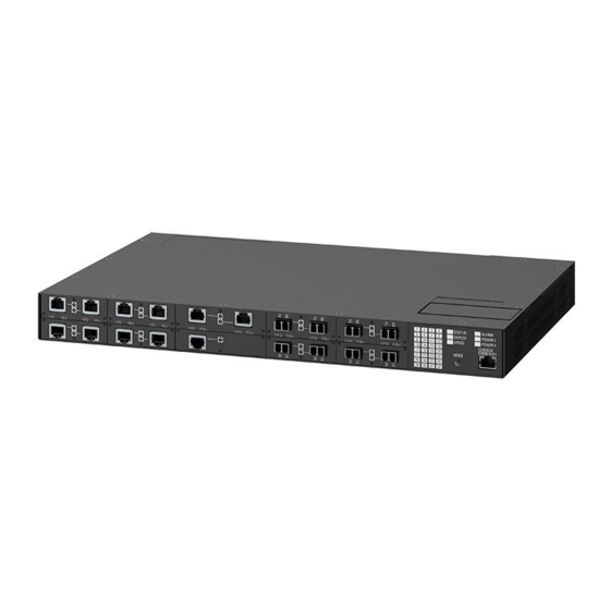
CSA/UL 60950-1 safety approved to 85 °C (185 °F) Description The RUGGEDCOM RSG2100F features various ports, controls and indicator LEDs on the display panel for connecting, configuring and troubleshooting the device. The display panel can be located on the rear, front or top of the device, depending on the mounting configuration. -
Page 10: Required Tools And Materials
"Connect- ing to the Device (Page 23)". Required Tools and Materials The following tools and materials are required to install the RUGGEDCOM RSG2100F: Tools/Materials Purpose AC power cord (16 AWG) For connecting power to the device. -
Page 11: Cabling Recommendations
Siemens also does not recommend using copper Ethernet ports to interface with de- vices in the field across distances that could produce high levels of ground potential rise (i.e. -
Page 12: Supported Fiber Optic Cables
NOTICE Worn, damaged or missing seals must be replaced immediately. Replacement seals are available for purchase from Siemens. For more information, contact a Siemens Sales representative. There are three ways to determine if a security seal has been tampered with: •... - Page 13 Introduction 1.6 Tamper-Evident Security Seals For information about the placement of security seals, refer to the RUGGEDCOM RUGGEDCOM RSG2100F FIPS 140-2 Non-Proprietary Security Policy [https://sup- port.industry.siemens.com/cs/ww/en/view/109757984] RUGGEDCOM RSG2100F Installation Manual, 01/2020, C79000-G8976-1344-07...
-
Page 14: Installing The Device
Use of controls or adjustments or performance of procedures other than those speci- fied herein may result in hazardous radiation exposure. NOTICE This product contains no user-serviceable parts. Attempted service by unauthorized personnel shall render all warranties null and void. RUGGEDCOM RSG2100F Installation Manual, 01/2020, C79000-G8976-1344-07... -
Page 15: General Procedure
Installing the Device 2.1 General Procedure Changes or modifications not expressly approved by Siemens AG could invalidate specifications, test results, and agency approvals, and void the user's authority to operate the equipment. NOTICE This product should be installed in a restricted access location where access can only be gained by authorized personnel who have been informed of the restrictions and any precautions that must be taken. -
Page 16: Installing The Device In Hazardous Locations
2.3 Installing the Device in Hazardous Locations Installing the Device in Hazardous Locations The RUGGEDCOM RSG2100F is designed to comply with the safety standards for Class I, Division 2, Zone 2 hazardous locations where concentrations of flammable gases, vapors or liquids may be present, as opposed to normal operating environ- ments. -
Page 17: Mounting The Device
2.4.1 Mounting the Device to a Rack The RUGGEDCOM RSG2100F can be secured to a standard 48 cm (19 in) rack using separately purchased rack mount adapters. The adapters can be installed at the front or rear of the chassis. - Page 18 The device can be ordered with the communication ports located at the front or rear of the device. Placing the ports at the rear allows all data and power cabling to be in- stalled and connected at the rear of the rack. RUGGEDCOM RSG2100F Installation Manual, 01/2020, C79000-G8976-1344-07...
-
Page 19: 2.4.2 Mounting The Device On A Din Rail
2.4.2 Mounting the Device on a DIN Rail For DIN rail installations, the RUGGEDCOM RSG2100F can be equipped with pan- el/DIN rail adapters pre-installed on each side of the chassis. The adapters allow the device to be slid onto a standard 35 mm (1.4 in) DIN rail. -
Page 20: 2.4.3 Mounting The Device To A Panel
2.4.3 Mounting the Device to a Panel For panel installations, the RUGGEDCOM RSG2100F can be equipped with panelDIN rail adapters pre-installed on each side of the chassis. The adapters allow the device to be attached to a panel using screws. -
Page 21: Connecting The Failsafe Alarm Relay
Control of the failsafe relay output is configurable through RUGGEDCOM RSG2100F . One common application for this relay is to signal an alarm if a power failure oc- curs. For more information, refer to the RUGGEDCOM RSG2100F User Guide for the RUGGEDCOM RSG2100F. -
Page 22: Connecting Power
Figure 2.5 Failsafe Alarm Relay Wiring Connecting Power The RUGGEDCOM RSG2100F supports a single or dual redundant AC and/or DC pow- er supplies. The RUGGEDCOM RSG2100F can be equipped with either a screw-type or pluggable terminal block, which provides power to both power supplies . The screw-type ter- minal block is installed using Phillips screws and compression plates, allowing either bare wire connections or crimped terminal lugs. -
Page 23: 2.6.1 Connecting Ac Or Dc Power
Identify the internal power module (POWER 1 or POWER 2) appropriate for the power supply (AC or DC). Use these screws along with #6 ring lugs to secure the wires to the terminal block. Note For wiring options, refer to "Wiring Examples (Page 18)". RUGGEDCOM RSG2100F Installation Manual, 01/2020, C79000-G8976-1344-07... - Page 24 Install the supplied metal jumper between terminals 2, 4 and 6 to connect the surge ground terminals to the chassis ground terminal. The surge ground termi- nals are used as the ground conductor for all surge and transient suppression cir- cuitry internal to the unit. RUGGEDCOM RSG2100F Installation Manual, 01/2020, C79000-G8976-1344-07...
-
Page 25: 2.6.2 Wiring Examples
Make sure the supplied terminal block cover is always installed before the de- vice is powered. Install the terminal block cover. 2.6.2 Wiring Examples The following illustrate how to connect power to single and dual power supplies. RUGGEDCOM RSG2100F Installation Manual, 01/2020, C79000-G8976-1344-07... - Page 26 Installing the Device 2.6.2 Wiring Examples Figure 2.8 Single AC Power Supply Figure 2.9 Single DC Power Supply RUGGEDCOM RSG2100F Installation Manual, 01/2020, C79000-G8976-1344-07...
- Page 27 Installing the Device 2.6.2 Wiring Examples Figure 2.10 Dual AC Power Supply Figure 2.11 Dual DC Power Supply RUGGEDCOM RSG2100F Installation Manual, 01/2020, C79000-G8976-1344-07...
- Page 28 Installing the Device 2.6.2 Wiring Examples Figure 2.12 Dual AC/DC Power Supply RUGGEDCOM RSG2100F Installation Manual, 01/2020, C79000-G8976-1344-07...
- Page 29 Installing the Device 2.6.2 Wiring Examples RUGGEDCOM RSG2100F Installation Manual, 01/2020, C79000-G8976-1344-07...
-
Page 30: Device Management
The following describes the various methods for accessing the RUGGEDCOM RSG2100F console and Web interfaces on the device. For more detailed instructions, refer to the RUGGEDCOM RSG2100F User Guide for the RUGGEDCOM RSG2100F. RS232 Console Port Connect a workstation directly to the RS232 console port to access the boot-time control and RUGGEDCOM RSG2100F interfaces. -
Page 31: Configuring The Device
RI is not connected. Communication Ports Connect any of the available Ethernet ports on the device to a management switch and access the RUGGEDCOM RSG2100F console and Web interfaces via the device's IP address. For more information about available ports, refer to "Communication Ports (Page 25)". -
Page 32: Communication Ports
The exact configuration of the device can be determined by reading the factory data file through the RUGGEDCOM RSG2100F user interface. For more information about how to read the factory data file, refer to the RUGGEDCOM RSG2100F User Guide for the RUGGEDCOM RSG2100F. -
Page 33: Copper Ethernet Ports
Figure 4.2 Port LEDs Copper Ethernet Ports The RUGGEDCOM RSG2100F supports several 10/100/1000Base-TX Ethernet ports that allow connection to standard Category 5 (CAT-5) unshielded twisted-pair (UTP) cables with either RJ45 or Micro-D male connectors. The RJ45 and Micro-D connec- tors are directly connected to the chassis ground on the device and can accept CAT-5 shielded twisted-pair (STP) cables. -
Page 34: Fiber Optic Ethernet Ports
Jack), LC (Lucent Connector), SC (Standard or Subscriber Connector) or ST (Straight Tip) connectors. Make sure the Transmit (Tx) and Receive (Rx) connections of each port are properly connected and matched to establish a proper link. RUGGEDCOM RSG2100F Installation Manual, 01/2020, C79000-G8976-1344-07... -
Page 35: Sfp Transceivers
The RUGGEDCOM RSG2100F features two Small Form-Factor Pluggable (SFP) trans- ceiver sockets, which are compatible with a wide array of SFP transceivers available from Siemens. The following SFP transceivers are compatible with the RUGGEDCOM RSG2100F. For more information, including installation/removal instructions and ordering infor- mation, refer to the RUGGEDCOM SFP Transceiver Catalog [https://support.indus-... -
Page 36: Gbic Optic Ethernet Ports
Do not install or remove GBIC optical ports when an explosive atmosphere is present. CAUTION Electrical hazard – risk of damage to equipment Use only components certified by Siemens with RUGGEDCOM products. Damage to the module and device may occur if compatibility and reliability have not been prop- erly assessed. RUGGEDCOM RSG2100F... - Page 37 NOTICE Only install GBIC optical ports that are compatible with the RUGGEDCOM RSG2100F. Make sure all potential electrostatic build-up has been properly discharged to prevent electrostatic discharges (ESD). This can be accomplished by wearing an ESD-preventive wrist strap connected to either the chassis ground connector or a bare metal surface on the router/switch.
-
Page 38: Removing A Gbic Optical Port
ESD-preventive wrist trap connected to either the chassis ground connector or a bare metal surface on the router/switch. Disconnect the cable from the port and install the dust cap to the cable end. RUGGEDCOM RSG2100F Installation Manual, 01/2020, C79000-G8976-1344-07... - Page 39 Store the port in an ESD-safe bag or other suitable ESD-safe environment, free from moisture and stored at the proper temperature (-40 to 85 °C or -40 to 185 °F). Insert a dust plug into the socket opening to prevent the ingress of dust and dirt. RUGGEDCOM RSG2100F Installation Manual, 01/2020, C79000-G8976-1344-07...
-
Page 40: Technical Specifications
Technical Specifications This section details the specifications and operating conditions of the device. Power Supply Specifications The RUGGEDCOM RSG2100F can be equipped with the following power supplies: CAUTION Electrical hazard – risk of power supply failure or damage to the device Make sure power input to the device is within the specified input range. -
Page 41: Failsafe Relay Specifications
RUGGEDCOM RSG2100F. Note • Maximum segment length is greatly dependent on factors such as fiber quality, and the number of patches and splices. Consult a Siemens sales associate when determining maximum segment distances. RUGGEDCOM RSG2100F Installation Manual, 01/2020, C79000-G8976-1344-07... -
Page 42: Fiber Optic Ethernet Port Specifications
14.2 Typical. Typical distance. The maximum distance is greatly dependent on factors such as cable type, the number of connectors and number of splices. Consult a Siemens sales associates when determining maximum distances. Fast Ethernet (10/100 Mbps) Optical Specifications Mode... - Page 43 All optical power numbers are listed as dBm averages. Typical distance. The maximum segment length is greatly dependent on factors such as fiber quality, and the number of patches and splices. Consult a Siemens sales associates when determining maximum segment distances. GBIC Gigabit (1 Gbps) Transceiver Specifications Note GBIC transceivers have a temperature range of -40 to 85 °C (-40 to 185 °F), unless...
-
Page 44: Operating Environment
Typical distance. The maximum segment length is greatly dependent on factors such as fiber quality, and the number of patches and splices. Consult a Siemens sales associates when determining maximum segment distances. Operating temperature range of -20 to 85 °C (-4 to 185 °F) . - Page 45 Technical Specifications 5.8 Dimension Drawings 438.15 Figure 5.1 Overall Dimensions RUGGEDCOM RSG2100F Installation Manual, 01/2020, C79000-G8976-1344-07...
- Page 46 Technical Specifications 5.8 Dimension Drawings 32.77 21.08 11.68 479.29 478.79 4.57 Figure 5.2 Rack Mount Dimensions RUGGEDCOM RSG2100F Installation Manual, 01/2020, C79000-G8976-1344-07...
- Page 47 Technical Specifications 5.8 Dimension Drawings 11.7 10.4 476.3 486.4 Figure 5.3 Panel and DIN Rail Mount Dimensions RUGGEDCOM RSG2100F Installation Manual, 01/2020, C79000-G8976-1344-07...
-
Page 48: Certification
Certification The RUGGEDCOM RSG2100F device has been thoroughly tested to guarantee its con- formance with recognized standards and has received approval from recognized reg- ulatory agencies. Approvals This section details the standards to which the RUGGEDCOM RSG2100F complies. 6.1.1 This device meets the requirements of the following Canadian Standards Association (CSA) standards under certificate 16.70068356:... -
Page 49: 6.1.2 Csa/Sira
For the maximum ambient temperature, refer to the hazardous location label affixed to the device. 6.1.3 European Union (EU) This device is declared by Siemens AG to comply with essential requirements and other relevant provisions of the following EU directives: • EN 60950-1 Information Technology Equipment –... -
Page 50: Fcc
Methods of Measurement The device is marked with a CE marking and can be used throughout the European community. A copy of the CE Declaration of Conformity is available from Siemens AG. For contact information, refer to "Contacting Siemens (Page vi)". -
Page 51: 6.1.5 Fda/Cdrh
Quality management systems – Requirements 6.1.8 RoHS This device is declared by Siemens AG to meet the requirements of the following Ro- HS (Restriction of Hazardous Substances) directives for the restricted use of certain hazardous substances in electrical and electronic equipment: •... -
Page 52: Emc And Environmental Type Tests
Railway Applications – Electromagnetic Compatibility – Emission and Immunity of the Signaling and Telecommunications Apparatus EMC and Environmental Type Tests The RUGGEDCOM RSG2100F has passed the following Electromagnetic Compatibility (EMC) and environmental tests. EMC Type Tests per IEC 61850-3 Note •... - Page 53 EMC Immunity Type Tests per IEEE 1613 Note The RUGGEDCOM RSG2100F meets Class 2 requirements for an all-fiber configura- tion and Class 1 requirements for copper ports. Class 1 allows for temporary commu- nication loss, while Class 2 requires error-free and interrupted communications.
- Page 54 Change of Temperature Test Nb 5 Cycles, -40 to 85° 60068-2-14 C (40 to 185° F) Bump 10 g @ 16 ms Class 1 60255-21-2 Seismic Method A, Class 2 Class 1 60255-21-3 RUGGEDCOM RSG2100F Installation Manual, 01/2020, C79000-G8976-1344-07...
- Page 55 Certification 6.2 EMC and Environmental Type Tests RUGGEDCOM RSG2100F Installation Manual, 01/2020, C79000-G8976-1344-07...
- Page 56 Further Information Siemens RUGGEDCOM https://www.siemens.com/ruggedcom Industry Online Support (service and support) https://support.industry.siemens.com Industry Mall https://mall.industry.siemens.com Siemens AG Digital Industry Process Automation Postfach 48 48 90026 NÜRNBERG GERMANY...
Need help?
Do you have a question about the RUGGEDCOM RSG2100F and is the answer not in the manual?
Questions and answers