Siemens SIMATIC NET RUGGEDCOM RSG2488F Installation Manual
Rugged ethernet switches
Hide thumbs
Also See for SIMATIC NET RUGGEDCOM RSG2488F:
- Installation manual (56 pages) ,
- Installation manual (58 pages)

Related Manuals for Siemens SIMATIC NET RUGGEDCOM RSG2488F


Summary of Contents for Siemens SIMATIC NET RUGGEDCOM RSG2488F
- Page 1 Installation Manual SIMATIC NET Rugged Ethernet Switches RUGGEDCOM RSG2488F Edition 07/2021 https://www.siemens.com...
- Page 2 Preface Introduction Installing the Device SIMATIC NET Device Management Rugged Ethernet Switches RUGGEDCOM RSG2488F Modules Technical Specifications Installation Manual Certification 07/2021 C79000-G8976-1351-07...
- Page 3 Note the following: WARNING Siemens products may only be used for the applications described in the catalog and in the relevant technical documentation. If products and components from other manufacturers are used, these must be recommended or approved by Siemens. Proper transport, storage, installation, assembly, commissioning, operation and maintenance are required to ensure that the products operate safely and without any problems.
-
Page 4: Table Of Contents
Accessing Documentation ....................... v Registered Trademarks ......................v Warranty ..........................v Training ..........................vi Customer Support ........................vi Contacting Siemens ....................... vii Introduction ........................... 1 Feature Highlights ....................1 Description ......................2 Required Tools and Materials ................. 3 Decommissioning and Disposal ................3 Cabling Recommendations .................. - Page 5 Table of Contents Available Modules ....................26 Installing/Removing Line Modules ................ 26 Installing/Removing Power Modules ..............28 Technical Specifications ...................... 31 Power Supply Specifications ................31 Failsafe Alarm Relay Specifications ..............31 Supported Networking Standards ................ 32 Operating Environment ..................32 Mechanical Specifications ..................
-
Page 6: Preface
Warranty Siemens warrants this product for a period of five (5) years from the date of purchase, conditional upon the return to factory for maintenance during the RUGGEDCOM RSG2488F... -
Page 7: Training
Siemens Sales representative. Customer Support Customer support is available 24 hours, 7 days a week for all Siemens customers. For technical support or general information, contact Siemens Customer Support through any of the following methods: Online Visit http://www.siemens.com/automation/support-request... -
Page 8: Contacting Siemens
Preface Contacting Siemens Mobile App Install the Industry Online Support app by Siemens AG on any Android, Apple iOS or Windows mobile device and be able to: • Access Siemens' extensive library of support documentation, including FAQs and manuals •... - Page 9 Preface Contacting Siemens viii RUGGEDCOM RSG2488F Installation Manual, 07/2021, C79000-G8976-1351-07...
-
Page 10: Introduction
Reliability in Harsh Environments • Immunity to EMI and heavy electrical surges • Zero-Packet-Loss Technology • Supports Siemens FastConnect RJ-45 Cabling System • -40 to 85 °C (-40 to 185 °F) operating temperature (fan-less) RUGGEDCOM RSG2488F Installation Manual, 07/2021, C79000-G8976-1351-07... -
Page 11: Description
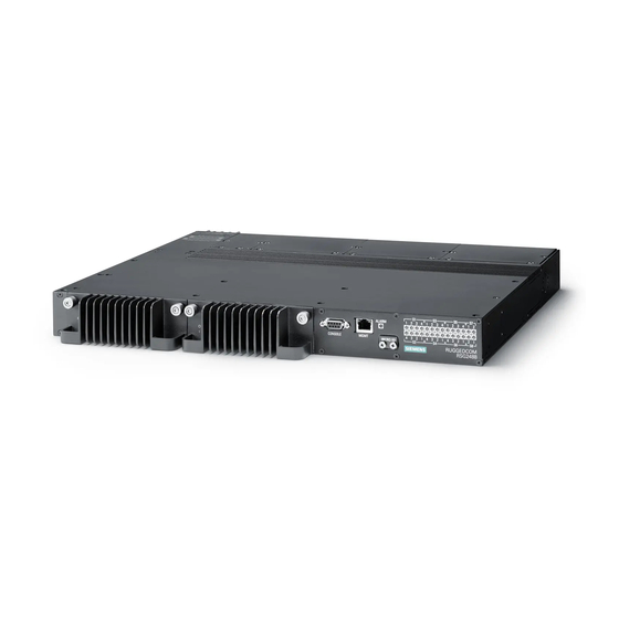
Introduction 1.2 Description • Conformal coated printed circuit boards (optional) Description The RUGGEDCOM RSG2488F features various ports, controls and indicator LEDs on the front panel for connecting, configuring and troubleshooting the device. Front Rear Power Modules Power Status LEDs RS-232 Serial Console Port (DB9) Management Port Alarm Indicator LED Access Plate... -
Page 12: Required Tools And Materials
Introduction 1.3 Required Tools and Materials Alarm Indicator LED The alarm indicator LED illuminates when an alarm condition exists. Access Plate The removable access plate provides access to the microSD slot. Use a microSD card to load/store the firmware and configuration for the device. -
Page 13: Cabling Recommendations
Siemens also does not recommend using copper Ethernet ports to interface with devices in the field across distances that could produce high levels of ground potential rise (i.e. greater than 2500 V), during line-to-ground fault conditions. -
Page 14: Supported Fiber Optic Cables
Introduction 1.5.3 Supported Fiber Optic Cables Cabling 1000Base- Required Action Category TX Compliant Verify TIA/EIA-568-A compliance. No action required. New installations should be designed with Category 5e or higher. No action required. > 6 Connector and wiring standards to be determined. Follow these recommendations for copper data cabling in high electrical noise environments: •... - Page 15 Introduction 1.6 Tamper-Evident Security Seals Replacement seals are available for purchase from Siemens. For more information, contact a Siemens Sales representative. There are three ways to determine if a security seal has been tampered with: • The seal is cut or torn •...
-
Page 16: Installing The Device
This product contains no user-serviceable parts. Attempted service by unauthorized personnel shall render all warranties null and void. Changes or modifications not expressly approved by Siemens AG could invalidate specifications, test results, and agency approvals, and void the user's authority to operate the equipment. -
Page 17: General Procedure
Visually inspect each item in the package for any physical damage. Verify all items are included. Note If any item is missing or damaged, contact Siemens for assistance. Mounting the Device The RUGGEDCOM RSG2488F is designed for maximum mounting and display flexibility. -
Page 18: Mounting The Device To A Rack
Installing the Device 2.3.1 Mounting the Device to a Rack Forced airflow is not required. However, any increase in airflow will result in a reduction of ambient temperature and improve the long-term reliability of all equipment mounted in the rack space. Note For detailed dimensions of the device with either rack, DIN rail or panel hardware installed, refer to... - Page 19 Installing the Device 2.3.2 Mounting the Device on a DIN Rail Mounting the Device To mount the device to a DIN rail, do the following: Hook the top teeth of the adapters onto the DIN rail. DIN Rail DIN Rail Adapter Screw Figure 2.2 Mounting the Device to a DIN Rail...
-
Page 20: Mounting The Device To A Panel
Installing the Device 2.3.3 Mounting the Device to a Panel Removing the Device To remove the device from a DIN rail, do the following: Remove screws from the DIN rail adapters on both sides of the device. DIN Rail DIN Rail Adapter Screw Figure 2.3 Removing the Device from a DIN Rail... -
Page 21: Connecting The Failsafe Alarm Relay
Installing the Device 2.4 Connecting the Failsafe Alarm Relay To mount the device to a panel, do the following: Place the device against the panel and align the adapters with the mounting holes. Screw Panel/DIN Rail Adaptor Figure 2.4 Panel Mounting Install the supplied screws to secure the adapters to the panel. Connecting the Failsafe Alarm Relay The failsafe relay can be configured to latch based on alarm conditions. -
Page 22: Connecting Power
Installing the Device 2.5 Connecting Power Pluggable Terminal Block for HI Power Supplies Screw-Type Terminal Block for HIP Power Supplies Normally Open Terminal Common Terminal Normally Closed Terminal Figure 2.5 Failsafe Alarm Relay Wiring Connecting Power The RUGGEDCOM RSG2488F supports dual redundant AC and/or DC power supplies that can be installed in any combination. -
Page 23: Connecting High Ac/Dc Power
Installing the Device 2.5.1 Connecting High AC/DC Power PS1 terminals. High voltage wiring is always made to the upper Hi terminal block and low voltage (24/48 V) wiring is always made to the lower Lo terminal block. • Use minimum #16 gage wiring when connecting terminal blocks. •... -
Page 24: Connecting Low Dc Power
Installing the Device 2.5.2 Connecting Low DC Power Connect the positive wire from the power source to the positive/live (+/L) terminal on the terminal block. Screw-Type Terminal Block for HIP Power Supplies Pluggable Terminal Block for HI Power Supplies Positive/Live (+/L) Terminal for PS1 Neutral/Negative (-/N) Terminal for PS1 Positive/Live (+/L) Terminal for PS2 Neutral/Negative (-/N) Terminal for PS2... -
Page 25: Grounding The Device
Installing the Device 2.5.3 Grounding the Device Connect the positive wire from the power source to the positive terminal on the terminal block. Screw-Type Terminal Block for 24 and 48 Power Supply Pluggable Terminal Block for 24P and 48P Power Supply Positive Terminal for PS1 Negative Terminal for PS1 Positive Terminal for PS2... -
Page 26: Wiring Examples
Installing the Device 2.5.4 Wiring Examples M3 Ring Lug Figure 2.8 Chassis Ground Connection 2.5.4 Wiring Examples The following illustrate how to connect power to single and dual power supplies. Figure 2.9 Single High AC/DC Power Supply Figure 2.10 Single Low DC Power Supply RUGGEDCOM RSG2488F Installation Manual, 07/2021, C79000-G8976-1351-07... - Page 27 Installing the Device 2.5.4 Wiring Examples Figure 2.11 Dual High AC/DC Power Supply Figure 2.12 Dual Low DC Power Supply RUGGEDCOM RSG2488F Installation Manual, 07/2021, C79000-G8976-1351-07...
- Page 28 Installing the Device 2.5.4 Wiring Examples Figure 2.13 High AC/DC Power Supply and Low DC Power Supply RUGGEDCOM RSG2488F Installation Manual, 07/2021, C79000-G8976-1351-07...
- Page 29 Installing the Device 2.5.4 Wiring Examples RUGGEDCOM RSG2488F Installation Manual, 07/2021, C79000-G8976-1351-07...
-
Page 30: Device Management
Device Management This section describes how to connect to and manage the device. Connecting to the Device The following describes the various methods for accessing the RUGGEDCOM RSG2488F console and Web interfaces on the device. For more detailed instructions, refer to the RUGGEDCOM ROS-F Configuration Manual for the RUGGEDCOM RSG2488F. -
Page 31: Configuring The Device
Device Management 3.2 Configuring the Device Name Description Clear To Send Reserved (Do Not Connect) The management port is a 10/100Base-TX copper Ethernet port with an RJ45 connector. The following is the pin-out for the management port: Figure 3.2 RJ45 Management Port Name Description Transmit Data+... -
Page 32: Inserting/Removing The Microsd Card
Device Management 3.3 Inserting/Removing the MicroSD Card Inserting/Removing the MicroSD Card The RUGGEDCOM RSG2488F accepts a microSD card for storing configuration files and/or software updates. NOTICE Configuration hazard – risk of data loss The microSD card must not be removed or replaced during normal operation of the device. - Page 33 Device Management 3.3 Inserting/Removing the MicroSD Card RUGGEDCOM RSG2488F Installation Manual, 07/2021, C79000-G8976-1351-07...
-
Page 34: Modules
Modules The RUGGEDCOM RSG2488F features slots for up to eight field-replaceable line modules, which can be used to expand and customize the capabilities of the device to suit specific applications. A variety of modules are available, each featuring a specific type of communication port: copper Ethernet, fiber optic Ethernet and Small Form-factor Pluggable (SFP). -
Page 35: Available Modules
Available Modules A variety of modules are available for use with the RUGGEDCOM RSG2488F. For more information, refer to the RUGGEDCOM Modules Catalog [https:// support.industry.siemens.com/cs/us/en/view/109757282] for the RUGGEDCOM RSG2488F. Installing/Removing Line Modules Upon installing a new line module in the device, all features associated with the module are available in RUGGEDCOM RSG2488F. - Page 36 Modules 4.2 Installing/Removing Line Modules Pull the module from the chassis to disconnect it. Module Chassis Screw Figure 4.2 Removing a Module Install a new module or a blank module (to prevent the ingress of dust and dirt). [Optional] If necessary, install the device in the rack. Connect power to the device.
-
Page 37: Installing/Removing Power Modules
Modules 4.3 Installing/Removing Power Modules Insert the new module into the slot. Module Chassis Screw Figure 4.3 Installing a Module Tighten the screws to secure the module. [Optional] If necessary, install the device in the rack. Connect power to the device. Installing/Removing Power Modules The RUGGEDCOM RSG2488F supports dual redundant power supply modules. - Page 38 Modules 4.3 Installing/Removing Power Modules Prevent the ingress of water, dirts and other debris that may lead to premature equipment failure. Always make sure slots are not left empty. Note Power modules are hot swappable. When installing/removing a power module, it is not necessary to turn off power to the device.
- Page 39 Modules 4.3 Installing/Removing Power Modules Insert the module into the empty slot. Screws Power Supply Chassis Figure 4.6 Installing a Power Module Hand-tighten the screws to secure the power module to the chassis. Turn on power to the device and confirm the module is receiving and supplying power.
-
Page 40: Technical Specifications
Technical Specifications This section provides important technical specifications related to the device. Power Supply Specifications Note Use the internal fuse rating to determine the size of the external circuit breaker/fuse. Note When determining cable lengths, make sure the minimum input voltage for the power supply is provided at the power source. -
Page 41: Supported Networking Standards
Technical Specifications 5.3 Supported Networking Standards Supported Networking Standards 1000 Standard 10 Mbps 100 Mbps Notes Mbps IEEE 802.1AB Link Layer Discovery Protocol (LLDP) IEEE 802.1D MAC bridges IEEE 802.1Q VLAN (Virtual LAN) IEEE 802.1p Priority levels IEEE 802.1x Port-based network access control IEEE 802.3 10Base-T IEEE 802.3u... - Page 42 Technical Specifications 5.6 Dimension Drawings 442.4 Figure 5.1 Overall Dimensions RUGGEDCOM RSG2488F Installation Manual, 07/2021, C79000-G8976-1351-07...
- Page 43 Technical Specifications 5.6 Dimension Drawings 483.5 465.2 21.1 Figure 5.2 Rack Mount Dimensions RUGGEDCOM RSG2488F Installation Manual, 07/2021, C79000-G8976-1351-07...
- Page 44 Technical Specifications 5.6 Dimension Drawings 480.5 490.6 DIN Rail Centerline Figure 5.3 Panel and Din Rail Mount Dimensions 110.0 21.8 Figure 5.4 4-Port Line Module Dimensions RUGGEDCOM RSG2488F Installation Manual, 07/2021, C79000-G8976-1351-07...
- Page 45 Technical Specifications 5.6 Dimension Drawings 49.8 21.8 Figure 5.5 2-Port Line Module Dimensions 43.9 129.8 Figure 5.6 Power Module Dimensions RUGGEDCOM RSG2488F Installation Manual, 07/2021, C79000-G8976-1351-07...
-
Page 46: Certification
CSA/EN/IEC/UL 62368-1 Information Technology Equipment – Safety – Part 1: General Requirements) 6.1.2 European Union (EU) This device is declared by Siemens AG to comply with essential requirements and other relevant provisions of the following EU directives: • EN 62368-1 Information Technology Equipment –... -
Page 47: Fcc
Products with Respect to the Restriction of Hazardous Substances The device is marked with a CE marking and can be used throughout the European community. A copy of the CE Declaration of Conformity is available from Siemens AG. For contact information, refer to "Contacting Siemens (Page vii)". -
Page 48: Rohs
Certification 6.1.6 RoHS 6.1.6 RoHS This device is declared by Siemens AG to meet the requirements of the following RoHS (Restriction of Hazardous Substances) directives for the restricted use of certain hazardous substances in electrical and electronic equipment: • China RoHS 2... - Page 49 Certification 6.2 EMC and Environmental Type Tests Test Description Test Levels Severity Levels IEC 61000-4-3 Radiated RFI Enclosure Ports 20 V/m Note IEC 61000-4-4 Burst (Fast Signal Ports ± 4 kV @ 2.5 Transient) and 5 kHz DC Power Ports ± 4 kV @ 2.5 and 5 kHz AC Power Ports Earth Ground Ports...
- Page 50 Relay Output) DC Power Ports 5 kV AC Power Ports Siemens-specified severity levels EMC Immunity Type Tests per IEEE 1613 Note The RUGGEDCOM RSG2488F meets Class 2 requirements for an all-fiber configuration and Class 1 requirements for copper ports. Class 1 allows for temporary communication loss, while Class 2 requires error-free and interrupted communications.
- Page 51 Certification 6.2 EMC and Environmental Type Tests Environmental Type Tests Test Description Test Levels IEC 60068-2-1 Cold Temperature Test Ad -40 °C (-40 °F), 16 Hours IEC 60068-2-2 Dry Heat Test Bd 85 °C (185 °F), 16 Hours IEC 60068-2-14 Change of Temperature Test Nb 5 Cycles, -40 to 85°...
- Page 52 Further Information Siemens RUGGEDCOM https://www.siemens.com/ruggedcom Industry Online Support (service and support) https://support.industry.siemens.com Industry Mall https://mall.industry.siemens.com Siemens AG Digital Industry Process Automation Postfach 48 48 90026 NÜRNBERG GERMANY...
Need help?
Do you have a question about the SIMATIC NET RUGGEDCOM RSG2488F and is the answer not in the manual?
Questions and answers