Table of Contents
Advertisement
Quick Links
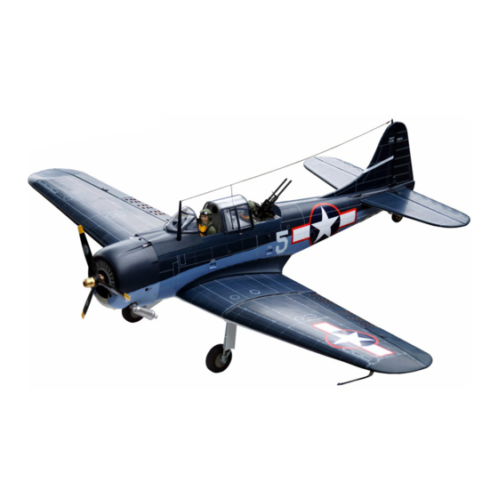
U.S NAVY DIVE BOMBER
VQ No: VQA123
Instruction manual / Montageanleitung
SPECIFICATIONS
Wingspan:.........................2060mm (81.1in)
Length:................................1450mm (57 in)
Electric Motor:.....................See next pager
Gas Engine:................................. 26-30cc
RTF Weight: 7Kg / 15.5lbs (Will vary with
Equipment Used).
Radio:...............7-8 Channel / 10-11 Servos
Function: Ailerons-Elevator-Rudder-Throttle
Flaps-Optional Retractable Landing Gear.
WARNING! This radio controlled model is NOT a toy. If modified or flown carelessly it could go out of controll and
cause serious human injury or property damage. Before flying your airplane, ensure the air field is spacious enough.
Always fly it outdoors in safe areas and seek professional advice if you are unexperienced.
ACHTUNG! Dieses ferngesteuerte Modell ist KEIN Spielzeug! Es ist für fortgeschrittene Modellflugpiloten bestimmt,
die ausreichende Erfahrung im Umgang mit derartigen Modellen besitzen. Bei unsachgemässer Verwendung kann
hoher Personen- und/oder Sachschaden entstehen. Fragen Sie in einem Modellbauverein in Ihrer Nähe um
professionelle Unterstätzung, wenn Sie Hilfe im Bau und Betrieb benötigen. Der Zusammenbau dieses Modells ist
durch die vielen Abbildungen selbsterklärend und ist für fortgeschrittene, erfahrene Modellbauer bestimmt.
Radio control model / Flugmodel
ALL BALSA, PLYWOOD CONSTRUCTION AND ALMOST READY TO FLY
TECHNISCHE DATEN
Spannweite:...................................2060mm
Lange:............................................1450mm
Elektroantrieb.............(siehe nächste Seite)
Verbrennerantrieb:..........................26-30cc
Fluggewicht:..........................................7Kg
Fernsteuerung......7-8 Kanal / 10-11 Servos
Advertisement
Table of Contents

Subscribe to Our Youtube Channel
Related Manuals for VQ Model SBD-5 DAUNTLESS


Summary of Contents for VQ Model SBD-5 DAUNTLESS
- Page 1 Radio control model / Flugmodel U.S NAVY DIVE BOMBER VQ No: VQA123 ALL BALSA, PLYWOOD CONSTRUCTION AND ALMOST READY TO FLY Instruction manual / Montageanleitung TECHNISCHE DATEN SPECIFICATIONS Wingspan:......2060mm (81.1in) Spannweite:........2060mm Length:........1450mm (57 in) Lange:..........1450mm Electric Motor:.....See next pager Elektroantrieb.....(siehe nächste Seite) Gas Engine:.........
- Page 2 REQUIRED FOR OPERATION (Purchase separately) Spinner hub Extension cord for aileron servos: 80cm(x2) Extension cord for flap and brake servos: 50cm(x4) Extension cord for retract servos: 30cm(x2) Extension cord for Rx battery pack: 30cm(x1) Extension cord for Elevator servos: 80cm(x2) Minimum 7-8 channels radio with 10 mini servos and 1 standard Servo (for GP).
-
Page 3: Fixed Gear
1- Fixed gear 3x20mm Plastic strap Main gear (right) Gear mount (plywood) Ply gear mount plate Ply gear mount plate Main gear (left) Square plastic 3x20mm Plastic strap Gear mount Square plastic (plywood) 3x20mm screw..16 Main landing gear... - Page 4 2- Electric retract GEAR SWITCH...
-
Page 5: Joining The Wing
3- Cover 4- Joining the wing 25x960mm aluminum tube... - Page 6 5- Servo Aileron servo Brake servo hatch (ply 3mm) Flap servo Included with the radio set Flap and brake push rod (one end to servo) Flap and brake control horn Aileron servo Hatch WING BOTTOM AIL. Servo mount Control horn ....2 2x30mm ..4...
- Page 7 6- Joining the wing ..2 5x20mm screws...
- Page 8 7- Engine Note: Remove the magnetic canopy Hatch first. Step 1 Step 2 Step 3 Step 4 Step 5...
-
Page 9: Electric Motor
8- Engine Step 6 9- Fuel tank Filler tube Rubber stopper Air tube Stopper To engine 10- Electric Motor... - Page 10 11- Magnetic canopy hatch 12- Cowling...
-
Page 11: Horizontal Stabilizer
13- Horizontal stabilizer Elevator servo hatch HORIZONTAL STABILIZER (Bottom-view) 6mm diameter dowel... -
Page 12: Tail Wheel
14- Horizontal stabilizer Note: The holes on the surface of the bottom of the horizontal stabilizer are pre-drilled at factory. 2.mm drill bit BOTTOM Aluminum 3x10mm screw tube inside 3x10mm screw ..2 Control horn Connector ..2 ....2 2x20mm ..4 Secure the horizontal stabilizer in place using 3x10mm screw. - Page 13 16- Rudder 2.5mm Rudder control horn 1.5mm 1.5mm...
- Page 14 17- Guns...
- Page 15 18- Bomb...
- Page 16 19- Bomb 20- Bomb 11mm diameter aluminum tube 2mm diameter steel wire Silicon tube...
- Page 17 21- Bomb Nylon control horn 2x6mm screw 1.5mm...
- Page 18 22- Hook 8mm diameter aluminum tube Wing - bottom view BLACK NYLON TUBE 23- Decor Black nylon wire Wing surface Do the same way with other side Black nylon wire WING- TOP VIEW...
-
Page 19: Rudder Servo
24- Rudder servo Connector ....2 Magnetic Pilot sitter Switch hole Remove before installing servo FUSELAGE TOP-VIEW Tail wheel push rod Rudder push rod 25- Guns - Antenna... -
Page 20: Control Surface
26- Balance Note: Adjust the location of the battery pack to achieve this C.G location. (128 ~ 133mm) DO NOT try to fly an out-of balance model! Wing center section 27- Control surface (20mm) (20mm) AILERON STROKE (15mm) (15mm) ELEVATOR STROKE (40mm) (25mm) CENTER FLAP STROKE...
Need help?
Do you have a question about the SBD-5 DAUNTLESS and is the answer not in the manual?
Questions and answers