
Related Manuals for MTU 16V4000M73


Summary of Contents for MTU 16V4000M73
-
Page 1: Operating Instructions
Operating Instructions Diesel engine with exhaust gas aftertreatment 16V4000M73 16V4000M73L MS150123/01E... - Page 2 All information in this publication was the latest information available at the time of going to print. MTU Friedrichshafen GmbH reserves the right to change, delete or supplement the information provided as and when required.
-
Page 3: Table Of Contents
9) for Series 4000, marine applications, IMO aftertreatment – Overview III (provisional) 4 Technical Data 8 Task Description 4.1 Product data 16V4000M73, 16V4000M73L, 8.1 SOLAS IMO Tier III (preliminary) 8.1.1 SOLAS shielding as per MTN 5233 – 4.2 Product data of SCR catalytic converter Installation 4.3 Product –... - Page 4 8.16 Oil Filtration / Cooling 8.5.1 Valve protrusion – Measurement 8.5.2 Valve gear – Lubrication 8.16.1 Automatic oil filter – Overview 8.5.3 Valve clearance – Check and adjustment 8.16.2 Automatic oil filter – Preparatory steps 8.5.4 Cylinder head cover – Removal and 8.16.3 Automatic oil filter ‒...
- Page 5 9 Appendix A 8.24.2 Engine Control Unit ECU 9 – Plug connection 9.1 List of abbreviations check 9.2 MTU Contact/Service Partners 8.24.3 Engine Monitoring Unit EMU 8 – Plug connection check 8.24.4 Interface module EIM plug connections – 10 Appendix B Check 8.24.5 Engine governor ECU 9 –...
-
Page 6: Safety
(→ Page 7). Replacing components with emission labels On all MTU engines fitted with emission labels, these labels must remain on the engine throughout its opera- tional life. Exception: Engines used exclusively in land-based, military applications other than by US government agen- cies. -
Page 7: Correct Use Of All Products
• With preservation approved by the manufacturer in accordance with the (→ Preservation and Represerva- tion Specifications of the manufacturer) • With spare parts approved by the manufacturer in accordance with the (→ Spare Parts Catalog/MTU con- tact/Service partner) • In the original as-delivered configuration or in a configuration approved by the manufacturer in writing (al- so applies to engine control/parameters) •... -
Page 8: Personnel And Organizational Requirements
1.3 Personnel and organizational requirements Organizational measures of the user/manufacturer This manual must be issued to all personnel involved in operation, maintenance, repair, assembly, installa- tion, or transportation. Keep this manual handy in the vicinity of the product such that it is accessible to operating, maintenance, repair, assembly, installation, and transport personnel at all times. -
Page 9: Safety Regulations For Initial Start-Up And Operation
1.4 Safety regulations for initial start-up and operation Safety regulations for initial start-up Install the product correctly and carry out acceptance in accordance with the manufacturer's specifications before putting the product into service. All necessary approvals must be granted by the relevant authorities and all requirements for initial startup must be fulfilled. - Page 10 Operation of electrical equipment When electrical equipment is in operation, certain components of these appliances are electrically live. Follow the applicable operating and safety instructions when operating the devices and heed warnings at all times. 10 | Safety | MS150123/01E 2017-05...
-
Page 11: Safety Regulations For Assembly, Maintenance, And Repair Work
1.5 Safety regulations for assembly, maintenance, and repair work Safety regulations for work prior to assembly, maintenance, and repair Have assembly, maintenance, or repair work carried out by qualified and authorized personnel only. Allow the product to cool down to less than 50 °C (risk of explosion for oil vapors, fluids and lubricants, risk of burning). - Page 12 Never use the product as a climbing aid. When working high on the equipment, always use suitable ladders and work platforms. Special instructions for outdoor areas: There must be no risk of slipping e.g. due to icing. Removing, installing and cleanliness Pay particular attention to cleanliness at all times.
- Page 13 Before starting welding work: • Switch off the power supply master switch. • Disconnect the battery cables or actuate the battery isolating switch. • Separate the electrical ground of electronic equipment from the ground of the unit. No other assembly, maintenance, or repair work must be carried out in the vicinity of the product while weld- ing is in progress.
- Page 14 Do not secure cables on lines carrying fluids. Do not use cable ties to secure lines. Always use connector pliers to tighten union nuts on connectors. Subject the device as well as the product to functional testing on completion of all repair work. The emergen- cy stop function must be tested in particular.
-
Page 15: Fire Prevention And Environmental Protection, Fluids And Lubricants, Indirect Materials
The safety data sheet may be obtained from the relevant manufacturer or from MTU. Only use fluids and lubricants which have been approved by the manufacture and are specified in the Fluids and Lubricants Specifications. -
Page 16: Compressed Air
Lead • Adopt suitable measures to avoid the formation of lead dust. • Switch on extraction system. • Avoid direct contact with lead or pastes containing lead. • Do not inhale lead vapors. • Wash affected areas after contact with lead or substances containing lead. Compressed air •... -
Page 17: Standards For Safety Notices In The Text
1.7 Standards for safety notices in the text DANGER In the event of immediate danger. Consequences: Death, serious or permanent injury! • Remedial action. WARNING In the event of a situation involving potential danger. Consequences: Death, serious or permanent injury! •... -
Page 18: Transport
Make sure that the consistency and load-bearing capacity of the ground or support surface is adequate. Never set the engine down on its oil pan unless expressly authorized to do so by MTU. Set down the exhaust gas aftertreatment system in such a way than only the mounts, not the main body touch the ground. -
Page 19: Lifting Instructions
2.2 Lifting instructions DANGER Suspended load. Danger to life! • Use appropriate lifting devices and appliances. • Never stand beneath a suspended load. DANGER Falling from great heights. Risk of serious injury – danger to life! • When working high on the equipment, always use suitable ladders or work platforms. •... - Page 20 Take note of the engine center of gravity Refer to the installation/arrangement drawings for details of the center of gravity of the engine. Lifting instructions – SCR catalytic converter without bypass 1 Max. admissible diagonal B 1057 mm F 921 mm pull 120°...
- Page 21 Lifting the SCR catalytic converter without bypass 1 Sling 2 Holder 3 Bearing Follow the instructions below when lifting the SCR catalytic converter: • When bypass is installed: Do not secure crane to bypass. Bypass must be removed when lifting by crane. •...
-
Page 22: Crankshaft Transport Locking Device
2.3 Crankshaft transport locking device Special tools, Material, Spare parts Designation / Use Part No. Qty. Torque wrench, 10–60 Nm F30452769 Ratchet adapter F30027340 Torque wrench, 60–320 Nm F30452768 Ratchet adapter F30027341 Engine oil Transport locking device Note: The transport locking device on both sides protects the crankshaft bearings from shocks and possible vibra- tion damage during engine transport. - Page 23 Fitting the transport locking de- vice on driving end (KS) Note: Attach plate (6) only to the upper part of the openings. Secure the plates (6) with screws (4) and washers (5) at the bores on both sides of the flywheel housing and tighten to the specified tightening torque.
- Page 24 Installing guard plates and en- gine supports (if applicable) on driving end (KS) Note: Screw on guard plates and engine support (where applicable) only with the screws supplied or with the screws removed from the guard plates or engine supports. Install engine supports (3) on both sides with guard plates, washers (1) and screws (2) and tighten to speci- fied tightening torque tightening.
-
Page 25: General Information
3 General Information 3.1 Engine side and cylinder designations 1 Left engine side (A-side) 3 Right engine side (B-side) 2 Engine free end in accord- 4 Engine driving end in ac- ance with DIN ISO 1204 cordance with (KGS = Kupplungsgegen- DIN ISO 1204 (KS = Kup- seite) plungsseite) -
Page 26: Product Layout
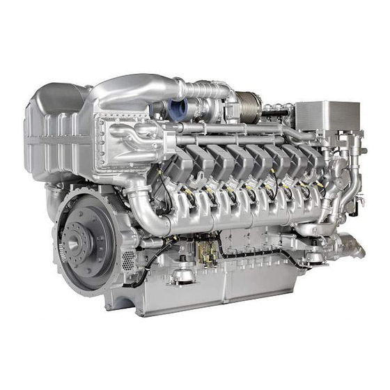
3.2 Product layout 16V diesel engine with SCR catalytic converter 1 Horizontal air filter 5 SCR catalytic converter 9 Pre-delivery module 2 Exhaust pipe bellows 6 Bypass line (*) 10 Power distribution 3 Exhaust system (optional) 7 Heat shield (*) Shown without insulation 8 DCM (Distributed Control 4 Connecting pipe (*) Module) control unit... -
Page 27: Engine - Overview
3.3 Engine – Overview Engine layout – 16V 1 Oil cooler 7 Cylinder head cover 13 Automatic oil filter 2 Coolant expansion tank 8 Charge-air pipework 14 Fuel filter 3 Crankcase breather 9 Oil filler neck 15 Centrifugal oil filter(s) 4 Air filter 10 Oil pan 16 Engine governor... -
Page 28: Scr Catalytic Converter - Overview
3.4 SCR catalytic converter – Overview SCR catalytic converter – Overview 1 SCR catalytic converter 6 Supply units 11 Wiring harness 2 Bypass line (*) 7 Bearing 12 Exhaust inlet flange to after- 3 SOLAS insulation 8 DCM (Distributed Control treatment system (*) 4 Heat shield Module) - Page 29 SCR catalytic converter – Overview without SOLAS insulation 1 Exhaust pipe bellows (*) 5 Heat shield 9 Exhaust flap main flow (*) 2 Bypass line (*) 6 Replaceable catalyst mod- 10 Exhaust outlet flange from 3 Dosing units ules aftertreatment system (*) 4 Supply units 7 Bearing 11 Exhaust flap bypass flow (*)
-
Page 30: Product Description
3.5 Product description Description of the diesel engine with exhaust gas aftertreatment Engine The engine is a liquid-cooled four-stroke diesel engine, rotating counterclockwise (seen from driving end), with direct injection, sequential turbocharging and charge-air cooling. The engine is monitored by an engine control and monitoring system (ADEC). Monitoring in the engine room is carried out by the engine control and monitoring unit (LOP). - Page 31 • Interface to ECU and EMU • MCS5 dialog interface • Control of an MTU lube-oil priming pump (power components in separate MTU PPC Box) • Connection facility for an MTU Local Operating Station (LOS) The engine interface comprises two parts. The first part is integrated in the engine wiring harness via a Tyco connector X52, 62-pin.
- Page 32 2 Cleaning cycle 3 ditto MTU marine engines of the Series 4000M53R to …M93L are suitable for low-load operation. State-of-the-art design and equipment features, e.g. TE coolant circuit, sequential turbocharging, jacketed, coolant-cooled exhaust lines, Common Rail fuel injection and cylinder cutout allow engine operation at low load.
- Page 33 Nevertheless, low-load operation at engine load below 15% of the nominal rating is permitted for max. 100 hours. In order to avoid inadmissible oil carbon and/or carbon particle deposits in the engine, it is rec- ommended to carry out a cleaning cycle for at least 20 minutes after extended low-load operation periods. During the cleaning cycle, engine speed (power) must be increased step by step until all exhaust turbocharg- ers are running.
- Page 34 High-pressure connections 1 Jacketed pipe 8 Thrust ring 15 Union nut 2 HP line 9 Union nut 16 Thrust ring 3 O-ring 10 Union nut 17 External pipe of HP line 4 Union nut 11 Connecting piece 18 Internal pipe of HP line 5 Recess for O-ring 12 Snap ring 19 Ball-type seal area...
-
Page 35: Sensors And Actuators - Overview
3.6 Sensors and actuators – Overview Plan view 12V4000M The following overview drawings also apply to 16V engines. B4.21 Exhaust bulk temperature, A B7 Lube oil temperature B34.1 Fuel pressure after filter side B5.3 Lube oil pressure before fil- F33 Coolant level B3 Intake air temperature B4.22 Exhaust bulk temperature, B B44.1 Turbocharger A speed... - Page 36 Left engine side 12V4000M B5.1 Lube oil pressure after filter XY1.1 Pneumatic starter B57.6 Main bearing temperature (B5.2 optional) B57.2 Main bearing temperature B57.7 Main bearing temperature B50 Crankcase pressure B57.3 Main bearing temperature XG03 Battery-charging generator B4.A1-Ax Cylinder exhaust tempera- B57.4 Main bearing temperature ture A1 (optional) B57.5 Main bearing temperature...
- Page 37 Right engine side 12V4000M B4.A1-Ax Cylinder exhaust tempera- B16 Coolant pressure B9 Charge-air temperature ture A1 B21 Raw water pressure (option) B44.2 Turbocharger B speed B77.B1-Bx Splash-oil temperature for XA80 DCM, SCR connection conrod bearings (option) MS150123/01E 2017-05 | General Information | 37...
- Page 38 Free end 12V4000M F46 H-Fuel Leakage B1 Camshaft speed B6.2 Coolant temperature (op- B33 Fuel temperature (rail) B54 Oil refill pump pressure tion) B6 Coolant temperature 38 | General Information | MS150123/01E 2017-05...
- Page 39 Driving end 12V4000M B13 Crankshaft speed S37.1 Safety switch S37.2 Safety switch B13.2 Crankshaft speed (option) MS150123/01E 2017-05 | General Information | 39...
- Page 40 SCR catalytic converter, free end X41 DCM connector to ECU B85.1 T-Exhaust before SCR, A X3 Connection to ECU9 X42 DCM connector for power side B85.3 T-Exhaust before SCR, B supply B102 P-Urea Solution PFM after side X43 DCM connector for compo- Filter B88.5 NOx before SCR, B side nents...
- Page 41 SCR catalytic converter, left side M81.3 Dosing unit 1.1 M80.1X2 X-VE 1.1 / X2 M80.3X2 X-VE 1.3 / X2 M81.4 Dosing unit 1.2 M80.2X1 X-VE 1.2 / X1 XWA1 Adaptation bypass M81.5 Dosing unit 1.3 M80.2X2 X-VE 1.2 / X2 M80.1X1 X-VE 1.1 / X1 M80.3X1 X-VE 1.3 / X1 MS150123/01E 2017-05 | General Information | 41...
- Page 42 SCR catalytic converter, right side M81.6 Dosing unit 2.1 M80.4X1 X-VE 2.1 / X1 M80.5X2 X-VE2.2 / X2 M81.7 Dosing unit 2.2 M80.4X2 X-VE 2.1 / X2 M80.6X1 X-VE 2.3 / X1 M81.8 Dosing unit 2.3 M80.5X1 X-VE2.2 / X1 M80.6X2 X-VE 2.3 / X2 42 | General Information | MS150123/01E 2017-05...
- Page 43 SCR catalytic converter, driving end K100.1X1 Relay 1 connector 1 actua- B85.6 T-Exhaust after SCR M60.1 X-SCR Bypass Flap 1 B88.8 NOx after SCR M60.2 X-SCR Bypass Flap 2 K100.1X2 Relay 1 connector 2 actua- B100.2 X-Ammoniac Sensor after XWA1 Adaptation bypass K100.2X1 Relay 2 connector 1 actua- B91.8 P-Exhaust after SCR K100.2X2 Relay 2 connector 2 actua-...
-
Page 44: Wiring Harness, Engine With Exhaust Gas Aftertreatment - Overview
3.7 Wiring harness, engine with exhaust gas aftertreatment – Overview Engine wiring harness, sensors – connector assignment Governor ECU B44.1 Exhaust turbocharger A speed Camshaft speed B44.2 Exhaust turbocharger B speed Intake air temperature HP fuel pressure B4.21 Exhaust gas temperature, A-side Charge-air before recirculation B4.22 Exhaust temperature, B-side... - Page 45 Wiring harness, SCR catalytic converter – connector assignment K100.2X1 Relay 2 connector 1 actuator X41.1 Connector DCM system 1/1 K100.2X2 Relay 2 connector 2 actuator X41.2 Connector DCM system 1/2 M60.1 X-SCR Bypass Flap 1 X41.3 Connector DCM system PFM M60.2 X-SCR Bypass Flap 2 X41.4...
- Page 46 Engine wiring harness for injectors 16V Y39Ax Injectors, engine A-side E4.x KF thermostat heating X3 Adaptation governor ECU Y39Bx Injectors, engine B-side 46 | General Information | MS150123/01E 2017-05...
- Page 47 Engine wiring harness for EIM XD1 Adaptation dialog unit XB19 Adaption starting-air pres- X11 Adaption EMU Power XD1.E Ground XD1 sure X1 Connection to ECU X37 Connection for start inter- X52 Connection to EIM engine lock XY1 Adaption starting system MS150123/01E 2017-05 | General Information | 47...
- Page 48 Engine wiring harness for electric starter 1 EIM terminals 2 Fuse F1 3 Starter terminals 48 | General Information | MS150123/01E 2017-05...
- Page 49 Wiring harness for SCR catalytic converter M81.5 Dosing unit 1.3 M81.7 Dosing unit 2.2 X43.2 Connector DCM sensor 1/2 M81.3 Dosing unit 1.1 M80.4X1 X-VE 2.1 / X1 X41.2 Connector DCM system M81.4 Dosing unit 1.2 M80.4X2 X-VE 2.1 / X2 B91.7 P-Exhaust before SCR M80.5X1 X-VE2.2 / X1 X43.3 Connector DCM sensor...
- Page 50 Wiring harness for SCR catalytic converter B100.2 X-Ammoniac Sensor after K100.2X2 Relay 2 connector 2 actua- B85.6 T-Exhaust after SCR M60.2 X-SCR Bypass Flap 2 XWA1 Adaptation bypass K100.1X2 Relay 1 connector 2 actua- B88.8 NOx after SCR K100.2X1 Relay 2 connector 1 actua- B91.8 P-Exhaust after SCR K100.1X1 Relay 1 connector 1 actua- M60.1 X-SCR Bypass Flap 1...
-
Page 51: Technical Data
4 Technical Data 4.1 Product data 16V4000M73, 16V4000M73L, IMO Tier III (preliminary) Legend DL Reference value: Continuous power; Continuously attainable power at standard conditions BL Reference value: Fuel stop power; Maximum engine power; Not continuously attainable in some appli- cations (margin for load fluctuations) - Page 52 General conditions (for maximum power) Intake depression (new filter) mbar Intake depression, max. mbar Model related data (basic design) Cylinder arrangement: V angle Degrees (°) Bore Stroke Cylinder displacement Liters 4.31 4.31 Total displacement Liters 68.96 68.96 Number of inlet valves per cylinder Number of exhaust valves per cylinder Raw-water circuit (open circuit) Raw water pump: Inlet pressure, min.
- Page 53 Starter (electric) Rated starter voltage (standard rating) Starter (with air/hydraulic starter motor) Starting-air pressure before starter motor, min. Starting-air pressure before starter motor, max. Inclinations, standard oil system (reference: waterline) Longitudinal inclination, continuous max. driving end down (Op- Degrees tion: max. operating inclinations) (°) Longitudinal inclination, temporary max.
- Page 54 Noise Exhaust noise, attenuated (EGA 1) - BL (free-field sound pressure dB(A) level Lp, 1 m distance, ISO 6798, +3 dB(A) tolerance) Engine surface noise with attenuated intake noise (intake silenc- dB(A) er) - BL (free-field sound power level Lp, 1 m distance, ISO 6798, +2 dB(A) tolerance) 54 | Technical Data | MS150123/01E 2017-05...
-
Page 55: Product Data Of Scr Catalytic Converter
4.2 Product data of SCR catalytic converter SCR catalytic converter – Technical data Design criteria Unit Value Max. exhaust mass flow kg/s Exhaust temperature in continuous operation °C Max. exhaust temperature °C Max. surface temperature incl. outside insulation acc. to °C SOLAS requirements Inlet flange (2x) -
Page 56: Product - Main Dimensions
4.3 Product – Main dimensions Engine – Main dimensions Engine model Length (A) Width (B) Height (C) Height (D) 12V4000M73L 3021 mm 1850 mm 2071 mm 636 mm 16V4000M73L 3610 mm 1850 mm 2071 mm 636 mm 56 | Technical Data | MS150123/01E 2017-05... - Page 57 SCR catalytic converter – Main dimensions Width (A) Height (B) Length (C) Length (D) 1736 mm 1885 mm 307 mm 2806 mm MS150123/01E 2017-05 | Technical Data | 57...
-
Page 58: Firing Order
4.4 Firing order Cylinders Firing order A1-B5-A5-B3-A3-B6-A6-B2-A2-B4-A4-B1 A1-A7-B4-B6-A4-B8-A2-A8-B3-B5-A3-A5-B2-A6-B1-B7 58 | Technical Data | MS150123/01E 2017-05... -
Page 59: Operation
5 Operation 5.1 LOP controls LOP controls Item Measure Start engine via the automation system (→ Automation system Operating In- structions). MS150123/01E 2017-05 | Operation | 59... -
Page 60: Putting The Engine Into Operation After Extended Out-Of-Service Periods (>3 Months)
☑ Preservation and Represervation Specifications A001070/.. are available. Putting into operation after extended out-of-service periods (>3 months) Item Action Engine Depreserve (→ MTU Preservation and Represervation Specifications A001070/..). Lube oil system Check engine oil level (→ Page 203); Preheat engine oil as necessary. -
Page 61: Putting The Engine Into Operation After Scheduled Out-Of-Service-Period
5.3 Putting the engine into operation after scheduled out-of- service-period Preconditions ☑ Engine is stopped and starting disabled. Putting into operation Item Action Lube oil system Check engine oil level (→ Page 203); Preheat engine oil as necessary. Coolant circuit Check coolant level (→... -
Page 62: Starting The Engine Via The Automation System
5.4 Starting the engine via the automation system Starting the engine via the automation system Item Task Automation system Start engine via the automation system (→ Automation system Operating In- structions). 62 | Operation | MS150123/01E 2017-05... -
Page 63: Operational Checks
5.5 Operational checks DANGER Components are moving or rotating. Risk of crushing, danger of parts of the body being caught or pulled in! • Operate the engine at low load only. Keep clear of the danger zone of the engine. WARNING High level of engine noise when the engine is running. -
Page 64: Tasks After Extended Out-Of-Service Periods (>3 Weeks)
5.6 Tasks after extended out-of-service periods (>3 weeks) Tasks after extended out-of-service periods (>3 weeks) Note: Operate fuel treatment system for at least 5 minutes. Start up fuel treatment system (→ Page 67). Shut down fuel treatment system (→ Page 79). 64 | Operation | MS150123/01E 2017-05... -
Page 65: Fuel Treatment System Control Cabinet - Controls
5.7 Fuel treatment system control cabinet – Controls Item Color Lettering Meaning/function Green Signal lamp Indicates “Pump running” Signal lamp Indicates “Pump fault” Yellow Illuminated Indicates “Water drain” / Press to drain water manually pushbutton Illuminated Indicates “Water alarm” / Press to acknowledge pushbutton Yellow Signal lamp... -
Page 66: Checks Prior To Start-Up
Check tank and the entire pipework for cleanness. If microorganisms are detected: a) Clean affected components. b) Disinfect affected components with biocides (→ MTU Fluids and Lubricants Specifications A001061/..). Close drain valves on housing. Open all supply and discharge valves. -
Page 67: Fuel Treatment System - Initial Start-Up
5.9 Fuel treatment system – Initial start-up Overview of fuel treatment system 1 Pressure-free overflow 9 Ball valve, outlet 17 Automatic water drain 2 Bypass 1 10 Check valve 700 mbar 18 Water level electrode 3 Bypass 2 11 Check valve 5 mbar 19 Ball valve, sample extrac- 4 Safety valve, 3 bar 12 Return to overflow tank... - Page 68 Initial start-up: HAT Replace fuel filter on engine (→ Page 155). Note: Determine the suction pressure upstream of the engine-mounted fuel delivery pump. Install pressure gage in fuel supply line from Yard fuel system to engine. Switch on fuel treatment system and operate it for some minutes (→ Page 70). Result: Fuel is drawn from the tank (24).
- Page 69 Simulating power failure (emergency): SAT Switch on fuel treatment system (→ Page 70). Start engine (→ Page 62). Run engine at idling speed. Switch off pump (21) at switchgear cabinet (20). Result: The engine-mounted fuel delivery pump draws fuel via bypass (2) directly from tank (24). Check suction pressure at the engine-mounted fuel delivery pump.
-
Page 70: Fuel Treatment System - Switching On
5.10 Fuel treatment system – Switching on Preconditions ☑ The on-board power supply is switched on. NOTICE Risk of damage to engine/system. Risk of severe damage to property! • Before switching on, ensure that the engine/system is ready for operation. •... -
Page 71: Engine With Exhaust Gas Aftertreatment - Emergency Stop Via Automation System
Automation system Emergency stop via the automation system (→ Operating Instructions Auto- mation System). Overview of emergency stop functions Normal stop Emergency stop Emergency stop MTU designa- Higher-level emergency Emergency stop function tion "Power-Off SCR"(*) stop function "Emergency Engine Stop"... - Page 72 When servicing, wait until the circulation cooling follow-up time has expired (up to 10 hours) before actuating the “Power-Off SCR” switch to avoid destroying the dosing units as a result of overheating. 72 | Operation | MS150123/01E 2017-05...
-
Page 73: Engagement Via Lop
5.12 Engagement via LOP DANGER In Local mode, the propulsion plant is controlled from the engine room. The person controlling the ves- sel has no visual contact with the surrounding area. Risk of collision and serious injury! • Only operate the vessel using the LOP when a second person is keeping lookout and is ready to alert the person at the LOP to any potential hazards. -
Page 74: Disengaging From Lop
5.13 Disengaging from LOP DANGER In Local mode, the propulsion plant is controlled from the engine room. The person controlling the ves- sel has no visual contact with the surrounding area. Risk of collision and serious injury! • Only operate the vessel using the LOP when a second person is keeping lookout and is ready to alert the person at the LOP to any potential hazards. -
Page 75: Waterjet - Flushing From Lop (Optional)
5.14 Waterjet – Flushing from LOP (optional) Preconditions ☑ LOCAL OPERATION illuminated switch is lit brightly (local operating mode is active). ☑ Waterjet-BucketVessel at standstill and waterjet bucket is below the waterline. ☑ Engine speed is in engagement window. ☑ No external engagement interlock is active. NOTICE Waterjet flushing puts excessive strain on the bearings. -
Page 76: Engine Shutdown Via The Automation System
5.15 Engine shutdown via the automation system NOTICE Stopping the engine when it is running at full load causes extreme stress to the engine. Risk of overheating, damage to components! • Before shutting down, disengage gear and run the engine at idle speed for at least 10 minutes until engine temperatures have dropped and constant values are displayed. -
Page 77: Engine With Exhaust Gas Aftertreatment - Stopping Via Automation System
Item Action Automation system Stopping engine via the automation system (→ Automation system Operating Instructions). Overview of operating modes Operating mode Stopping in normal operation MTU designa- Manual Switch-Off tion Engine Stop Key-Switch SCR/IMO II/IMO III (am LOP) Function Engine stop... -
Page 78: After Shutting Down The Engine
Switch off. Air intake and exhaust sys- Out-of-service-period > 1 week: • Seal engine's air and exhaust sides. Engine Out-of-service-period > 1 month: • Carry out engine preservation (→ MTU Preservation and Represervation Specifications A001070/..) 78 | Operation | MS150123/01E 2017-05... -
Page 79: Fuel Treatment System - Shutdown
5.18 Fuel treatment system – Shutdown Shutting down fuel treatment system Press the illuminated pushbutton "Water drain" on the switch cabinet until water discharge from the outlet stops. Switch off fuel treatment system. Close ball valve at the inlet to the fuel treatment system. Close ball valve at the outlet of the fuel treatment system. -
Page 80: Plant - Cleaning
5.19 Plant – Cleaning Preconditions ☑ Engine is stopped and starting disabled. ☑ No operating voltage applied. Special tools, Material, Spare parts Designation / Use Part No. Qty. High-pressure cleaner (→ Tools Catalog) Cleaner (Hakupur 50/136) X00056700 WARNING Compressed air gun ejects a jet of pressurized air. Risk of injury to eyes and damage to hearing, risk of rupturing internal organs! •... -
Page 81: Maintenance
6 Maintenance 6.1 Maintenance task reference table [QL1] The maintenance tasks and intervals for this product are defined in the Maintenance Schedule. The Mainte- nance Schedule is a standalone publication. The task numbers in this table provide reference to the maintenance tasks specified in the Maintenance Schedule. - Page 82 Task Measures W1765 SCR supply unit: Replace filter element. (→ Page 174) W1766 Replace reducing agent lines. (→ Page 183) W1767 Replace dosing unit. (→ Page 180) W1768 Replace supply unit. (→ Page 177) W1769 Replace NOx sensor in SCR system. (→...
-
Page 83: Control Cabinet Of Fuel Treatment System - Troubleshooting
7 Troubleshooting 7.1 Control cabinet of fuel treatment system – Troubleshooting Water alarm Cause Corrective action When the maximum water level is 1. Press illuminated pushbutton 'Water alarm' for acknowledgment. reached, the water level electrode 2. In addition to the automatic water drain function, water can also be opens the water drain valve and drained manually: Press illuminated pushbutton 'Water drain'. -
Page 84: Troubleshooting
7.2 Troubleshooting Engine does not turn when starter is actuated Cause Corrective action Battery low or faulty u Charge or replace (see separate documentation). u Check firm seating of cable connections (see separate Battery: Cable connections faulty documentation). Engine wiring faulty u Check (→... - Page 85 Air intake temperature too high Engine coolant mixture incorrect 1. Check engine coolant level (→ Page 242). 2. Check engine coolant (MTU test kit) (→ Page 249). u Replace (→ Instructions for Exchange of Sub-assemblies). Charge-air cooler contaminated Charge-air pressure too low...
- Page 86 Exhaust back pressure too high Cause Corrective action SCR substrate clogged with: 1. Briefly connect engine load to blow off SCR substrates (soot • Soot (resulting from engine emission possible). malfunction, e.g. injector 2. If exhaust back pressure does not fall: Contact Service. failure) •...
- Page 87 White exhaust gas Cause Corrective action u Run engine to reach operating temperature. Engine is not at operating temperature Charge-air cooler leaking 1. Check drain for coolant discharge and obstruction (→ Page 170). 2. Replace intercooler (→ Instructions for Exchange of Sub- assemblies).
- Page 88 Urea solution escapes from SCR system repeatedly in engine room Cause Corrective action u Check peripheral equipment, replace as necessary. Urea solution efflorescence (white deposit) Leaks, cracks in urea solution u Check for leakage, replace as necessary (→ Page 183). system White crystals on plug connections or urea solution system Cause...
-
Page 89: Fault Messages Of Engine Control Unit (Ecu 9) For Series 4000, Marine Applications, Imo Iii (Provisional)
7.3 Fault messages of Engine Control Unit (ECU 9) for Series 4000, marine applications, IMO III (provisional) 3 – HI T-Fuel Cause Corrective action The fuel temperature at sensor 1. Reduce power. B33 exceeded limit value 1. Fuel 2. Check fuel recooling system (if applicable). temperature is too high. - Page 90 19 – HI T-Exhaust A Cause Corrective action Exhaust temperature at sensor u Run injector test according to DiaSys description. Contact Service B4.21 exceeded limit value 1. if no DiaSys is available. Exhaust temperature is too high. 20 – SS T-Exhaust A Cause Corrective action u Run injector test according to DiaSys description.
- Page 91 26 – SS P-Diff-Lube Oil Cause Corrective action The differential oil pressure at 1. Replace engine oil filter (→ Page 207). sensors B5.1 and B5.3 exceeded 2. Contact Service. limit value 2. The differential oil pressure is too high. 27 – HI Level Leakage Fuel Cause Corrective action Switch F46 in the collecting tank...
- Page 92 34 – SS P-Diff-Fuel Cause Corrective action The differential pressure at 1. Replace fuel filter (→ Page 155). sensors B34.1 and B34.2 has 2. Contact Service. violated upper limit value 2. The differential pressure is too high. 36 – HI ETC2 Overspeed Cause Corrective action The secondary exhaust...
- Page 93 52 – SS T-Lube Oil Cause Corrective action The lube oil temperature at sensor 1. Check operation of cooler and fan (plant). B7 exceeded limit value 2. Lube- 2. Check engine coolant level (→ Page 242). oil temperature is too high. 3.
- Page 94 65 – LO P-Fuel Cause Corrective action The fuel pressure at sensor B34.1 1. Replace fuel filter (→ Page 155). went below limit value 1. Fuel 2. Replace fuel prefilter (→ Page 163). pressure is too low. 3. Contact Service. 66 –...
- Page 95 90 – SS Idle Speed Not Reached Cause Corrective action The engine has failed to reach idle 1. For hydraulic starter: Check pressure supply (plant) of starter. speed within the defined time 2. For electric starter: Check the starter power supply (plant). after reaching starter 3.
- Page 96 102 – AL Fuel Cons. Counter Defect Cause Corrective action The fuel consumption calculated u Contact Service. by the ECU and stored on stopping the engine cannot be read out properly on restarting the engine. 104 – AL Eng Hours Counter Defect Cause Corrective action The operating hours calculated by...
- Page 97 122 – HI T-ECU Cause Corrective action The temperature at the sensor 1. Disconnect power supply. inside the ECU exceeded the limit 2. Check power supply (plant). value. The temperature inside the 3. Contact Service. housing is too high. 141 – AL Power too high Cause Corrective action The average power value over the...
- Page 98 188 – AL CAN2 Bus Off Cause Corrective action CAN bus 2 to plant automation 1. Check connection between plant automation system and MTU system (e.g. Murphy display) is automation system. disrupted or defective. 2. Contact Service.
- Page 99 201 – SD T-Coolant Cause Corrective action The signal from the coolant 1. Check engine wiring (→ Page 268). temperature sensor (B6) on the 2. Contact Service. coolant distribution housing is faulty or missing. 202 – SD T-Fuel Cause Corrective action The signal from the fuel 1.
- Page 100 211 – SD P-Lube Oil Cause Corrective action The signal from the lube oil 1. Check engine wiring (→ Page 268). pressure sensor after filter (B5.1) 2. Contact Service. is faulty or missing. 212 – SD P-Coolant Cause Corrective action The coolant pressure sensor after 1.
- Page 101 221 – SD P-Diff Lube Oil Cause Corrective action The signals from lube oil pressure 1. Check engine wiring (→ Page 268). sensors B5.3 and/or B5.1 are 2. Contact Service. faulty or missing. 222 – SD Level Leakage Fuel Cause Corrective action The signal from the fuel leakage 1.
- Page 102 232 – SD Charger 1 Speed Cause Corrective action The signal from the A side ETC 1. Check engine wiring (→ Page 268). speed sensor (B44.1) is faulty or 2. Contact Service. missing. 233 – SD Charger 2 Speed Cause Corrective action The signal from the B side ETC 1.
- Page 103 270 – SD Frequency Input Cause Corrective action Signal at analog frequency input 1. Check engine wiring (→ Page 268). missing. 2. Contact Service. 321 – AL Wiring Cylinder A1 Cause Corrective action Short circuit fault in the injector 1. Check wiring of affected injector (→ Page 268). wiring for cylinder A1 or injector is 2.
- Page 104 327 – AL Wiring Cylinder A7 Cause Corrective action Short circuit fault in the injector 1. Check wiring of affected injector (→ Page 268). wiring for cylinder A7 or injector is 2. Replace injector (→ Page 148). defective. 3. Contact Service. 328 –...
- Page 105 334 – AL Wiring Cylinder B4 Cause Corrective action Short circuit fault in the injector 1. Check wiring of affected injector (→ Page 268). wiring for cylinder B4 or injector is 2. Replace injector (→ Page 148). defective. 3. Contact Service. 335 –...
- Page 106 341 – AL Open Load Cylinder A1 Cause Corrective action Disruption fault in injector wiring 1. Check wiring of affected injector (→ Page 268). to cylinder A1. 2. Contact Service. 342 – AL Open Load Cylinder A2 Cause Corrective action Disruption fault in injector wiring 1.
- Page 107 349 – AL Open Load Cylinder A9 Cause Corrective action Disruption fault in injector wiring 1. Check wiring of affected injector (→ Page 268). to cylinder A9. 2. Contact Service. 350 – AL Open Load Cylinder A10 Cause Corrective action Disruption fault in injector wiring 1.
- Page 108 357 – AL Open Load Cylinder B7 Cause Corrective action Disruption fault in injector wiring 1. Check wiring of affected injector (→ Page 268). cylinder B7. 2. Contact Service. 358 – AL Open Load Cylinder B8 Cause Corrective action Disruption fault in injector wiring 1.
- Page 109 371 – AL Wiring TO 1 Cause Corrective action Short circuit or wire break on 1. Check engine wiring (→ Page 268). transistor output 1 (TO 1). 2. Contact Service. 372 – AL Wiring TO 2 Cause Corrective action Short circuit or wire break on 1.
- Page 110 400 – AL Open Load Digital Input 1 Cause Corrective action Open load detected at digital 1. Check cabling (→ Page 268). input 1 of the ECU. 2. Contact Service. 401 – AL Open Load Digital Input 2 Cause Corrective action Open load detected at digital 1.
- Page 111 408 – AL Open Load Emerg. Stop Input ESI Cause Corrective action Open load at emergency stop 1. Check cabling (→ Page 268). input. 2. Contact Service. 410 – LO U-PDU Cause Corrective action The ECU voltage to control the 1.
- Page 112 444 – SD U-PDU Cause Corrective action Fault in the internal supply voltage u Contact Service. for the injector output stage. 445 – SD P-Ambient Air Cause Corrective action The signal from the ambient u Contact Service. pressure sensor in the ECU is faulty or missing.
- Page 113 476 – AL Crash Rec. Init. Error Cause Corrective action The Crash Recorder data module u Contact Service. was detected as being faulty after reading out the flash memory. 478 – AL Comb. Alarm Yel (Plant) Cause Corrective action This alarm is raised when a plant 1.
- Page 114 488 – HI ETC3 Overspeed Cause Corrective action The secondary exhaust 1. Reduce power. turbocharger speed at sensor 2. Contact Service. B44.3 has exceeded limit value 1. The exhaust turbocharger speed is too high. Cause: Fault or malfunction of another turbocharger.
- Page 115 536 – AL Wiring PWM_CM1 Cause Corrective action HP fuel control block M8 of the 1. Check engine wiring (→ Page 268). HP fuel pump cannot be activated. 2. Contact Service. 549 – AL Power Cut-Off detected Cause Corrective action The ECU operating voltage was 1.
- Page 116 596 – AL Develop PR Set Cause Corrective action The parameter record is used for u No action required. trials. The alarm remains active until a series-production parameter set was installed. 602 – AL CAN Engine Start Lock Cause Corrective action The ECU has received a start 1.
- Page 117 955 – AL Thermal Management active Cause Corrective action Thermal management was u No action required. activated as soot loading in the DPF has reached the limit. Regeneration has been initiated automatically. 973 – AL Check Sum IIG Cause Corrective action The IIG value entered does not 1.
- Page 118 1027 – AL Engine Cold Active Cause Corrective action This fault is signaled and the 1. Switch on preheater. “Engine Cold” function initiated if 2. Check preheater, overhaul as necessary (see manufacturer's one of the temperature values is documentation). below the defined limit. 3.
- Page 119 1183 – AL Invalid Measurement Config Cause Corrective action Selected measuring point not u Contact Service. activated or configured incorrectly. 1201 – AL Stop Start Low Power Supply Pow Cause Corrective action Engine start is blocked because 1. Check condition of batteries (plant). the supply voltage is too low.
-
Page 120: Task Description
8 Task Description 8.1 SOLAS 8.1.1 SOLAS shielding as per MTN 5233 – Installation Preconditions ☑ Engine is stopped and starting disabled. Special tools, Material, Spare parts Designation / Use Part No. Qty. Shield A5 735233000101 Shield A6 735233000102 Shield A7 735233000103 Shield A8 735233000104... -
Page 121: Installation Locations For Solas Shielding
8.1.2 Installation locations for SOLAS shielding General information Fit SOLAS shielding as per MTN 5233 by way of preference (→ Page 120). Shield unions with adhesive tape if SOLAS shielding as per MTN 5233 is not possible (→ Page 128). When affixing adhesive connections ensure that escaping fluid can flow out without pressure (→... - Page 122 Item Type of shielding Installation location Shield A8 Fuel line to HP pump Shield E5 Fuel line to HP pump Lube oil system, oil lines with oil pressure >1.8 bar Item Type of shielding Installation location 2 x shield A5 Actuating cylinder exhaust flap ETC B1 122 | SOLAS | MS150123/01E 2017-05...
- Page 123 Item Type of shielding Installation location 2 x shield A5 Actuating cylinder air flap ETC B1 3 x shield A5 T adapter for flap control ETC B1 Item Type of shielding Installation location 4 x shield A5 Distributor 3 x shield A5 Oil return MS150123/01E 2017-05 | SOLAS | 123...
- Page 124 Item Type of shielding Installation location Shield A7 Oil return * This shield must be installed on the assembly line. This position can no longer be accessed as soon as the intake housing is installed. Item Type of shielding Installation location Shield A7 Oil line to ETC Shield A5...
- Page 125 Item Type of shielding Installation location 2 x shield A5 Air recirculation valve Item Type of shielding Installation location Shield A6 Oil supply line to HP pump: To HP pump MS150123/01E 2017-05 | SOLAS | 125...
- Page 126 Item Type of shielding Installation location Shield B4 Oil supply line to HP pump: On equipment carrier * This shield must be installed on the assembly line. Assembly in this position is no longer possible after painting. Item Type of shielding Installation location Shield A7 ETC oil supply...
- Page 127 Item Type of shielding Installation location Shield B2 Oil line on equipment carrier Shield B2 Oil line on pressure reducing valve * This shield must be installed on the assembly line. Assembly in this position is no longer possible after painting.
-
Page 128: Adhesive Tape For Solas Shielding - Application
8.1.3 Adhesive tape for SOLAS shielding – Application Preconditions ☑ Engine is stopped and starting disabled. Special tools, Material, Spare parts Designation / Use Part No. Qty. Adhesive tape Applying adhesive tape – gener- al information Note: Use the cable clamp to make a drainage channel. -
Page 129: Engine
8.2 Engine 8.2.1 Engine – Barring manually Preconditions ☑ Engine is stopped and starting disabled. Special tools, Material, Spare parts Designation / Use Part No. Qty. Barring gear F6555766 Ratchet with extension F30006212 DANGER Rotating and moving engine parts. Risk of crushing, danger of parts of the body being caught or pulled in! •... -
Page 130: Engine - Barring With Starting System
8.2.2 Engine – Barring with starting system BlueLine automation system Starting barring procedure at LOP 8 (→ BlueLine Operating Instructions) BlueVision automation system Starting barring procedure at LOP 8 (→ BlueLine Operating Instructions) 130 | Engine | MS150123/01E 2017-05... -
Page 131: Cylinder Liner
8.3 Cylinder Liner 8.3.1 Cylinder liner – Endoscopic examination Preconditions ☑ Engine is stopped and starting disabled Special tools, Material, Spare parts Designation / Use Part No. Qty. Barring tool F6555766 Ratchet with extension F30006212 Endoscope Y20097353 Preparatory steps Remove cylinder head cover (→ Page 145). Remove injector (→... - Page 132 Compile endoscopic report using the table. Use technical terms to describe the liner surface (→ Page 133). Depending on findings: • Do not take any action or • carry out a further endoscopic examination as part of maintenance work or •...
-
Page 133: Cylinder Liner - Instructions And Comments On Endoscopic And Visual Examination
8.3.2 Cylinder liner – Instructions and comments on endoscopic and visual examination Terms used for endoscopic examination Use the terms listed below to describe the condition of the cylinder-liner surface in the endoscopic examina- tion report. Findings Explanations/Action Minor dirt scores Minor dirt scores can occur during the assembly of a new engine (honing products, particles, broken-off burrs). - Page 134 Evaluation of findings and further measures The findings in the start phase of oxidation discoloration and burn marks are similar. A thorough investigation and compliance with the above evaluation criteria allow an unambiguous evaluation. To avoid unnecessary disassembly work, it is recommended that another inspection be carried out after further operation of the engine.
-
Page 135: Crankcase Breather
8.4 Crankcase Breather 8.4.1 Crankcase breather – Oil mist separator replacement Preconditions ☑ Engine is stopped and starting disabled. Special tools, Material, Spare parts Designation / Use Part No. Qty. Engine oil Oil mist separator (→ Spare Parts Catalog) O-ring (→... -
Page 136: Valve Drive
8.5 Valve Drive 8.5.1 Valve protrusion – Measurement Preconditions ☑ Engine is stopped and starting disabled. Special tools, Material, Spare parts Designation / Use Part No. Qty. Measuring jig 1 Y4350009 Depth gage, 200 mm Y20000918 Measuring jig 2, optional Y4350010 Preparatory steps Remove cylinder head covers (→... - Page 137 Turn measuring unit screws (1) into the threads and tighten to specified torque using a torque wrench. Name Size Type Lubricant Value/Standard Screw Tightening torque 20 Nm Set all dial gages to 0. Unscrew measuring unit (2) from calibration plate (3). Step 1: Measure valve protrusion at the valve head with measuring jig 1 Check TDC position of piston in cylinder A1: •...
- Page 138 Release adjusting screw (1) and remove valve bridge. Do not remove rocker arm (2). Measure distance (A) between valve stem end and cylinder head top at the injector bore with depth gage. • The specified value for a new cylinder head: 93.8 mm.
- Page 139 Note: Do not remove rocker arm (2). Release adjusting screw (1) and remove valve bridge. Place measuring unit 2 (2) on the cylinder head (3). Turn measuring unit screws (1) into the threads provided for the cylinder head cover and tighten to specified torque using a torque wrench.
-
Page 140: Valve Gear - Lubrication
8.5.2 Valve gear – Lubrication Preconditions ☑ Engine is stopped and starting disabled. Special tools, Material, Spare parts Designation / Use Part No. Qty. Engine oil Valve gear – Lubrication Remove cylinder head covers (→ Page 145). Fill oil chambers of valve bridges with oil. Fill oil chambers of rocker arms and adjusting screws with oil. -
Page 141: Valve Clearance - Check And Adjustment
8.5.3 Valve clearance – Check and adjustment Preconditions ☑ Engine is stopped and starting disabled. ☑ Engine coolant temperature is max. 40 °C. ☑ Valves are closed. Special tools, Material, Spare parts Designation / Use Part No. Qty. Feeler gage Y20098771 Valve setting gauge Y4349603... - Page 142 Note: Danger of confusion: There might be an addi- tional OT/A1 mark (1) on the outer perimeter of the flywheel. The additional OT/A1 mark (1) (if fitted) on the outer perimeter of the flywheel must not be used for reference. Diagram for 8V engines –...
- Page 143 Diagram for 16V engines – Two crankshaft positions Diagram for 20V engines – Two crankshaft positions Checking valve clearance at two crankshaft positions Check TDC position of piston in cylinder A1: • If the rocker arms are unloaded on cylinder A1, the piston is in firing TDC. •...
-
Page 144: Adjusting Valve Clearance
Adjusting valve clearance Release locknut (1). Insert valve setting gauge (3) between valve bridge and rocker arm. Note: Replace or rectify adjusting screws and/or locknuts which do not move freely. Using angular screw driver, set adjusting screw (2) so that the specified valve clear- ance is provided. -
Page 145: Cylinder Head Cover - Removal And Installation
8.5.4 Cylinder head cover – Removal and installation Preconditions ☑ Engine is stopped and starting disabled. Special tools, Material, Spare parts Designation / Use Part No. Qty. Assembly compound (Kluthe Hakuform 30-15) X00067260 O-ring (→ Spare Parts Catalog) Removing cylinder head cover Clean very dirty cylinder head covers (1) prior to removal. -
Page 146: Injection Pump / Hp Pump
8.6 Injection Pump / HP Pump 8.6.1 HP fuel pump – Filling with engine oil Preconditions ☑ Engine is stopped and starting disabled. Special tools, Material, Spare parts Designation / Use Part No. Qty. Torque wrench, 10–60 Nm F30452769 Fuel suction device F30378207 Engine oil WARNING... - Page 147 Preparatory steps Loosen nut (2) and remove oil line (1) from HP pump. HP pump – Filling Remove union (1). Note: Excess engine oil runs into gear box. Use fuel suction device to fill HP pump with 2 liters of clean engine oil. Screw in union (1) and use torque wrench to tighten to specified tightening torque.
-
Page 148: Injector
8.7 Injector 8.7.1 Injector – Replacement Special tools, Material, Spare parts Designation / Use Part No. Qty. Injector (→ Spare Parts Catalog) Injector – Replacement Remove injector and install new one (→ Page 149). 148 | Injector | MS150123/01E 2017-05... -
Page 149: Injector - Removal And Installation (Jacketed Fuel System)
8.7.2 Injector – Removal and installation (jacketed fuel system) Preconditions ☑ Engine is stopped and starting disabled. Special tools, Material, Spare parts Designation / Use Part No. Qty. Installation/removal jig F6789889 Milling cutter F30452739 Torque screwdriver, 1–5 Nm F30452774 Torque wrench, 10–60 Nm F30452769 Ratchet bit F30027340... - Page 150 WARNING Internal tension and residual pressure in the HP fuel system.Parts can be ejected when loosening them. Risk of injury by ejected parts! • Only use specified tools and devices. • Wear goggles/facial protection. NOTICE Contamination of components. Damage to component! •...
- Page 151 Install installation/removal jig on the cylinder head. Remove injector with installation/removal jig. Remove the installation/removal jig. Note: The sealing ring (4) for sealing the combus- tion chamber must only be used once. Remove sealing ring (4) from injector or use a self-made wire hook or magnet to take it out of the cylinder head and dispose properly.
- Page 152 Note: Remove plugs on HP line only before installa- tion of the adapter. Remove plug. Use milling cutter to remove oil carbon from sealing face on cylinder head and protective sleeve. Note: The damper ring is already in place for new assembly.
- Page 153 Coat screw mating face (2) and thread with engine oil. Fit hold-down clamp (1) in correct position and install screw (2) by hand. Note: Make sure parts are perfectly clean. Apply engine oil to thread, sealing taper and thrust ring of adapter (3). Apply (Assembly compound (Kluthe Haku- form 30-15)) to O-rings on adapter (3).
- Page 154 Fit cable connector on injector. For new assembly: CDC parameters – Reset Note: Failure to reset drift compensation (CDC) will void the emissions certification of the engine. Reset drift compensation (CDC) with DiaSys® (→ Dialog system DiaSys® E531920/..). If DiaSys® is not available, contact Service.
-
Page 155: Fuel Filter
8.8 Fuel Filter 8.8.1 Fuel filter – Replacement Preconditions ☑ Engine is stopped and starting disabled. Special tools, Material, Spare parts Designation / Use Part No. Qty. Oil filter wrench F30379104 Fuel Easy-change filter (→ Spare Parts Catalog) DANGER Components are moving or rotating. Risk of crushing, danger of parts of the body being caught or pulled in! •... -
Page 156: Replacing Fuel Filter
Replacing fuel filter Note: • The left fuel filter (5) is cut out when the lever is in position (3) • The right fuel filter (4) is cut out when the lever is in position (7) Cut out fuel filter to be replaced. Pull locking pin (1) and turn lever (6) to the left or right stop. -
Page 157: Fuel Prefilter - Contamination Indicator Check
8.8.2 Fuel prefilter – Contamination indicator check DANGER Components are moving or rotating. Risk of crushing, danger of parts of the body being caught or pulled in! • Operate the engine at low load only. Keep clear of the danger zone of the engine. WARNING High level of engine noise when the engine is running. - Page 158 Switching over fuel prefilter 1 Filter B in operation 2 Filter A in operation Press button on lever. Turn lever to desired position and engage the button. The tip of the lever with the inscription always faces the filter that is in operation. When the tip faces downwards, both filters are in operation. 158 | Fuel Filter | MS150123/01E 2017-05...
-
Page 159: Fuel Prefilter - Draining
8.8.3 Fuel prefilter – Draining DANGER Components are moving or rotating. Risk of crushing, danger of parts of the body being caught or pulled in! • Operate the engine at low load only. Keep clear of the danger zone of the engine. WARNING Liquid or gaseous media, e.g. - Page 160 Open vent valves (1) of filter to be drained. Open drain valve (2). Drain water and contamination from filter un- til clean fuel emerges. Close drain valve (2). Open rotary slide valve (2) a little (turning to approx. 30°) to introduce fuel into the filter housing with the new filter element.
-
Page 161: Fuel Prefilter - Flushing
8.8.4 Fuel prefilter – Flushing Preconditions ☑ Positive pressure at the prefilter inlet. DANGER Components are moving or rotating. Risk of crushing, danger of parts of the body being caught or pulled in! • Operate the engine at low load only. Keep clear of the danger zone of the engine. WARNING Liquid or gaseous media, e.g. - Page 162 Open threaded vent plug (1) of the filter to be flushed. Remove drain valve (2) and drain fuel. Result: Fuel flows from filtered side back to the unfil- tered side, flushing the filter deposits down- wards out of the filter. Close threaded vent plug (1) and drain valve (2).
-
Page 163: Fuel Prefilter With Water Separator - Filter Element Replacement
8.8.5 Fuel prefilter with water separator – Filter element replacement Preconditions ☑ Positive pressure at the prefilter inlet Special tools, Material, Spare parts Designation / Use Part No. Qty. Torque wrench, 10–60 Nm F30452769 Ratchet bit F30027340 Filter element (→ Spare Parts Catalog) O-ring (→... - Page 164 Fuel prefilter with water separa- tor – Filter element replacement Cut out the filter to be replaced (A or B): 1 Filter A cut out 2 Filter B cut out Open vent valve (3) of the filter to be re- placed.
- Page 165 Open rotary slide valve (2) a little (turning to approx. 30°) to introduce fuel into the filter housing with the new filter element. Close vent valve (1) as soon as fuel emerges from vent pipe (4). Turn the rotary slide valve to the upright posi- tion (3) until it engages.
-
Page 166: Exhaust Turbocharger
8.9 Exhaust Turbocharger 8.9.1 Compressor wheel – Cleaning Preconditions ☑ Engine is stopped and starting disabled. Special tools, Material, Spare parts Designation / Use Part No. Qty. Torque wrench, 10–60 Nm F30452769 Ratchet adapter F30027340 Cleaner 40377 Engine oil Sealing rings 007603030101 Sealing rings 007603042101... - Page 167 Remove charge-air pipework (1) from exhaust turbocharger to intercooler. Remove oil lines (2). Loosen clamp (1). Remove intake housing (3) with actuating cyl- inder (2). Remove coolant lines (1) from compressor housing (3). Remove coolant vent line (2) from compres- sor housing (3).
- Page 168 Loosen and remove screws (1). Remove compressor housing (2). Compressor wheel – Cleaning Note: Never use a wire brush, scraper or similar ob- ject for cleaning! Clean compressor housing with a smooth paint brush or brush. Clean compressor wheel (2) and bearing housing (1).
- Page 169 Screw in screws (1) and tighten to specified tightening torque using a torque wrench . Name Size Type Lubricant Value/Standard Screw M10x18 Tightening torque (Engine oil) 20 Nm + 2.5 Nm Install coolant vent line and coolant lines on compressor housing. Install intake housing (3) with actuating cylin- der (2).
-
Page 170: Charge-Air Cooling
8.10 Charge-Air Cooling 8.10.1 Intercooler – Check water drain for coolant leakage and obstruction DANGER Moving or rotating parts. Risk of crushing, danger of limbs being caught up or drawn in! • Operate engine in lower load range only. Keep away from the danger zone of the engine. WARNING High level of engine noise when the engine is running. -
Page 171: Air Filter
8.11 Air Filter 8.11.1 Air filter – Replacement Special tools, Material, Spare parts Designation / Use Part No. Qty. Air filter (→ Spare Parts Catalog) Replacing air filter Remove old air filter and install new air filter (→ Page 172). Reset signal ring of contamination indicator (→... -
Page 172: Air Filter - Removal And Installation
8.11.2 Air filter – Removal and installation Preconditions ☑ Engine is stopped and starting disabled. Special tools, Material, Spare parts Designation / Use Part No. Qty. Torque screwdriver, 1–5 Nm F30452774 Removing and installing air fil- Release clamp (2). Remove air filter (1) and clamp (2) from con- necting flange of intake housing (3). -
Page 173: Air Intake
8.12 Air Intake 8.12.1 Service indicator – Signal ring position check Preconditions ☑ Engine is stopped and starting disabled. Checking signal ring position When the yellow piston (2) has reached the red-shaded Service lettering (3), replace air filter (→ Page 171). After installation of new filter, press reset button (1). -
Page 174: Exhaust Gas Aftertreatment
8.13 Exhaust Gas Aftertreatment 8.13.1 Supply unit – Filter element replacement Preconditions ☑ Engine was stopped with key switch and it was verified that circulation cooling is completed. ☑ SCR system switched off after completion of aftercooling phase. ☑ Shutoff devices for urea solution lines must be provided on-board. Special tools, Material, Spare parts Designation / Use Part No. - Page 175 Replacing filter element Note: Shutoff devices for urea solution lines must be provided on-board. Shut off supply and return line from pre-feed module to tank. Note: Clean with high-pressure cleaner / steam-jet cleaner as necessary. Clean supply unit prior to opening. Note: When removing the filter housing, small amounts of urea solution can escape.
- Page 176 Tighten filter housing (5) to specified torque using a torque wrench. Name Size Type Lubricant Value/Standard Filter housing 46A/F Tightening torque (Lubricant spray Bio- 80 Nm ±5 Nm lube L Spray) Open supply and return line from pre-feed module to tank before starting engine. 176 | Exhaust Gas Aftertreatment | MS150123/01E 2017-05...
-
Page 177: Supply Unit - Replacement
8.13.2 Supply unit – Replacement Preconditions ☑ Engine was stopped with key switch and it was verified that circulation cooling is completed. ☑ SCR system switched off after completion of aftercooling phase. ☑ Shutoff devices for urea solution lines must be provided on-board. Special tools, Material, Spare parts Designation / Use Part No. - Page 178 Remove retainer (2) with screws (4). Remove supply unit (3) with screws (1) from retainer (2). Installing supply unit Install retainer (2) on supply unit (3). Tighten screws (1) to specified torque using a torque wrench. Name Size Type Lubricant Value/Standard Screw Tightening torque...
- Page 179 Remove transport closures from urea solu- tion connections. Connect connector to urea solution inlet (2) (intake line). Connect connector to urea solution outlet (1) (pressure line). Connect HDSC connector of DCM box (3) and HDSC connector of dosing unit (4). Check supply unit connectors for leakage af- ter initial start-up.
-
Page 180: Dosing Unit - Replacement
8.13.3 Dosing unit – Replacement Preconditions ☑ Engine was stopped with key switch and it was verified that circulation cooling is completed. ☑ SCR system switched off after completion of aftercooling phase. ☑ Shutoff devices for urea solution lines must be provided on-board. Special tools, Material, Spare parts Designation / Use Part No. - Page 181 Removing dosing unit Note: Shutoff devices for urea solution lines must be provided on-board. Shut off supply and return line from pre-feed module to tank. Disconnect connector (1) from dosing unit. Remove urea solution supply line (3) and re- turn line (2). Remove screws (1, 2, 3).
- Page 182 Insert dosing unit with insulating molding (4) into opening in insulation cover. Secure dosing unit with screw (2). Then insert screw (3) and finally screw (1) at the top. Coat screws (3) with assembly compound. Tighten screws (1, 2, 3) to specified torque using a torque wrench. Name Size Type...
-
Page 183: Urea Solution Lines - Replacement
8.13.4 Urea solution lines – Replacement Preconditions ☑ Engine was stopped with key switch and it was verified that circulation cooling is completed. ☑ SCR system switched off after completion of aftercooling phase. ☑ Shutoff devices for urea solution lines must be provided on-board. WARNING Ammonia is created in case of fire or overheating. -
Page 184: Insulation Of Scr Housing And Scr Bypass - Check
8.13.5 Insulation of SCR housing and SCR bypass – Check Special tools, Material, Spare parts Designation / Use Part No. Qty. Insulating moldings/insulating mats (→ Spare Parts Catalog) Checking insulation of SCR housing and SCR bypass Note: • The insulation (1) of the SCR housing mainly consists of sheet metal (air gap in- sulation principle), part of the structure is a sandwich design (sheet metal, insulating... -
Page 185: Pre-Feed Module - Filter Element Replacement
8.13.6 Pre-feed module – Filter element replacement Preconditions ☑ Engine was stopped with key switch and it was verified that circulation cooling is completed. ☑ SCR system switched off after completion of aftercooling phase. ☑ Shutoff devices for urea solution lines must be provided on-board. Special tools, Material, Spare parts Designation / Use Part No. - Page 186 Pre-feed module – Filter ele- ment replacement Note: Shutoff devices for urea solution lines must be provided on-board. Shut off supply and return line from pre-feed module to tank. Provide an appropriate container to collect the urea solution. Clean pre-feed module (1) before opening it. Undo filter housing (2) with filter wrench and drain urea solution into a suitable container.
-
Page 187: Pre-Feed Module - Replacement
8.13.7 Pre-feed module – Replacement Preconditions ☑ Engine was stopped with key switch and it was verified that circulation cooling is completed. ☑ SCR system switched off after completion of aftercooling phase. ☑ Shutoff devices for urea solution lines must be provided on-board. Special tools, Material, Spare parts Designation / Use Part No. - Page 188 Removing pre-feed module Note: Shutoff devices for urea solution lines must be provided on-board. Shut off supply and return line from pre-feed module to tank. Provide suitable containers to collect urea solution. Disconnect connector from pressure sen- sor (3). Disconnect solenoid coil connectors (6) and (7).
-
Page 189: Exhaust Pressure Sensor - Measuring Lines Check
8.13.8 Exhaust pressure sensor – Measuring lines check Preconditions ☑ Operating voltage is switched off. Special tools, Material, Spare parts Designation / Use Part No. Qty. Digital multimeter with test leads, test clips and test prods (→ Tools Catalog) Cable (→... -
Page 190: Exhaust Pressure Sensor - Measuring Lines Cleaning
8.13.9 Exhaust pressure sensor – Measuring lines cleaning Special tools, Material, Spare parts Designation / Use Part No. Qty. Cleaner (Snow-White 11-0) X00054118 Cleaner (Hakupur 50/136) X00056700 WARNING Compressed air gun ejects a jet of pressurized air. Risk of injury to eyes and damage to hearing, risk of rupturing internal organs! •... -
Page 191: Scr Catalytic Converter - Mounting Alignment
8.13.10 SCR catalytic converter – Mounting alignment Special tools, Material, Spare parts Designation / Use Part No. Qty. Alignment jig F6794341 Torque wrench, 60–320 Nm F30452768 Torque wrench, 300–800 Nm F30047798 Engine oil DANGER Suspended load. Danger to life! • Use appropriate lifting devices and appliances. •... - Page 192 Note: It is sufficient to use one alignment jig, how- ever, using four devices to align all mounts at the same time makes the alignment proce- dure easier. Insert alignment jig (2) in this retainer (4) and in mount (3). If necessary, move or turn the mount to the correct position to ensure that it is properly seated in the retainer.
-
Page 193: Scr Catalytic Converter - Mounting Check
8.13.11 SCR catalytic converter – Mounting check SCR catalytic converter – Mounting check Item Findings Action Visually inspect resilient mounts. • Damage Replace (contact Service) • Deformation • Crack formation MS150123/01E 2017-05 | Exhaust Gas Aftertreatment | 193... -
Page 194: Scr Modules - Replacement
8.13.12 SCR modules – Replacement Preconditions ☑ Engine was stopped with key switch and it was verified that circulation cooling is completed. ☑ SCR system switched off after completion of aftercooling phase. Special tools, Material, Spare parts Designation / Use Part No. - Page 195 WARNING Exhaust gases are harmful to health and may cause cancer. Risk of poisoning and suffocation! • Keep the engine room well-ventilated at all times. • Repair leaking exhaust pipework immediately. WARNING Components have sharp edges. Risk of injury! • Wear protective gloves. CAUTION Restricted freedom of movement when performing maintenance work.
- Page 196 Removing SCR modules Undo V-band clamp (2) while holding cover (1). Note: Weight of cover: approx. 4 kg. Remove cover (1) with seal (3). Note: Risk of crushing! Weight of SCR module: ap- prox. 26 kg. Carefully pull SCR module (4) out of retaining pipe (7) by gently jiggling.
- Page 197 Note: There is no need to center the spaces be- tween the recesses. The recesses (arrowed) in the metal profile must engage precisely in the recesses on the SCR module. Note: • Do not throw, roll or drop SCR module. •...
- Page 198 Note: • Do not use lubricants to expediate assembly! • The maximum tightening torque of 25 Nm must not be exceeded! Tighten V-band clamp (2) to specified torque using a torque wrench. Name Size Type Lubricant Value/Standard Tightening torque 20 Nm Check that the clamp has settled into position, tap lightly all around with a rubber mallet then tighten once again to specified tightening torque.
-
Page 199: Nox Sensor - Replacement
8.13.13 NOx sensor – Replacement Preconditions ☑ Engine was stopped with key switch. ☑ SCR system switched off after completion of aftercooling phase. Special tools, Material, Spare parts Designation / Use Part No. Qty. Torque wrench, 10–60 Nm F30452769 Assembly compound (Molykote P 37) 50564 NOx sensor (→... - Page 200 Removing NOx sensors before and after SCR Note: Always replace the complete NOx sensor as- sembly including the evaluation unit. Loosen and disconnect connectors on the evaluation units (1). Unscrew NOx sensors (2) before SCR. Remove evaluation units (1). Note: Always replace the complete NOx sensor as- sembly including the evaluation unit.
- Page 201 Tighten hexagon (2) to specified torque using a torque wrench. Name Size Type Lubricant Value/Standard M20x1.5 Tightening torque 50 Nm ±10 Nm Connect connector (1) to all evaluation units latch it. Installing NOx sensors before and after SCR – used sensors Note: •...
-
Page 202: Starting Equipment
8.14 Starting Equipment 8.14.1 Starter – Condition check Preconditions ☑ Engine is stopped and starting disabled. Checking starter condition Check securing screws of starter for secure seating and tighten if required. Check wiring (→ Page 268). 202 | Starting Equipment | MS150123/01E 2017-05... -
Page 203: Lube Oil System, Lube Oil Circuit
8.15 Lube Oil System, Lube Oil Circuit 8.15.1 Engine oil level – Check Preconditions ☑ Engine is stopped and starting disabled. WARNING Oil is hot. Oil can contain residue/substances which are harmful to health. Risk of injury and poisoning! • Allow the product to cool to below 50 °C before beginning work. •... -
Page 204: Engine Oil - Change
8.15.2 Engine oil ‒ Change Preconditions ☑ Engine is stopped and starting disabled. ☑ Engine is at operating temperature. ☑ MTU Fluids and Lubricants Specifications (A001061/..) are available. Special tools, Material, Spare parts Designation / Use Part No. Qty. Torque wrench, 60–320 Nm... - Page 205 Tighten drain plugs (1) and (2) to specified torque using a torque wrench: Name Size Type Lubricant Value/Standard Screw M26x1.5 Tightening torque 100 Nm+10 Nm Filling with new oil Open cover (1) on filler neck. Pour oil in at filler neck up to “max.” mark at oil dipstick.
-
Page 206: Engine Oil - Sample Extraction And Analysis
8.15.3 Engine oil – Sample extraction and analysis Preconditions ☑ MTU Fluids and Lubricants Specifications (A001061/..) are available. Special tools, Material, Spare parts Designation / Use Part No. Qty. MTU test kit 5605892099/00 DANGER Components are moving or rotating. Risk of crushing, danger of parts of the body being caught or pulled in! •... -
Page 207: Oil Filtration / Cooling
8.16 Oil Filtration / Cooling 8.16.1 Automatic oil filter – Overview Automatic oil filter 1 Filter housing 9 O-ring 17 Screw 2 Oil filter element 10 Cover 18 Gearbox flange 3 O-ring 11 Screw 19 O-ring 4 Cover 12 Sealing ring 20 Sealing ring 5 Nut 13 Screw-fitting union... - Page 208 1 Sealing ring 8 Plug screw 15 Sealing ring 2 Plug screw 9 Sealing ring 16 Sealing ring 3 Sealing ring 10 Plug screw 17 Bypass valve 4 Plug screw 11 Sealing ring 18 O-ring 5 Sealing ring 12 Threaded bushing 19 Cover 6 Plug screw 13 Plug screw...
- Page 209 1 Screw 8 O-ring 15 Turbine housing 2 Securing bushing 9 Clamping ring 16 Impeller 3 Compression spring 10 Spring washer 17 Washer 4 Scavenge bushing 11 Screw 18 Stud 5 Sight glass 12 Screw 19 Nut 6 Flat gasket 13 Worm gear 7 O-ring 14 Grooved pin...
-
Page 210: Automatic Oil Filter Preparatory Steps
8.16.2 Automatic oil filter – Preparatory steps Preconditions ☑ Engine is stopped and starting disabled. Automatic oil filter preparatory steps Observe safety instructions. Remove centrifugal oil filter (→ Page 238). 210 | Oil Filtration / Cooling | MS150123/01E 2017-05... -
Page 211: Automatic Oil Filter - Removal
8.16.3 Automatic oil filter ‒ Removal Preconditions ☑ Preparatory steps have been completed. DANGER Suspended load. Danger to life! • Use appropriate lifting devices and appliances. • Never stand beneath a suspended load. WARNING Heavy part, risk of falling or overturning due to lack of stability. Risk of crushing body or limbs! •... -
Page 212: Draining Oil
Draining oil Remove plug screw (2) with sealing ring (1) and drain off oil into a suitable container. Removing automatic oil filter Note: Clean interface between automatic oil filter and coolant distribution housing. Attach automatic oil filter (1) to crane with a lightly tensioned lifting strap. -
Page 213: Automatic Oil Filter - Disassembly
8.16.4 Automatic oil filter – Disassembly Preconditions ☑ Automatic oil filter has been removed from engine. Automatic oil filter – Disassembly Observe safety instructions. Disassemble automatic oil filter as per overview drawing (→ Page 207). MS150123/01E 2017-05 | Oil Filtration / Cooling | 213... -
Page 214: Automatic Oil Filter - Cleaning
8.16.5 Automatic oil filter – Cleaning Special tools, Material, Spare parts Designation / Use Part No. Qty. Cleaner (Snow-White 11-0) X00054118 Cleaner (Hakupur 50/136) X00056700 WARNING Compressed air gun ejects a jet of pressurized air. Risk of injury to eyes and damage to hearing, risk of rupturing internal organs! •... -
Page 215: Automatic Oil Filter - Checking Flushing Arm Rotation
8.16.6 Automatic oil filter – Checking flushing arm rotation Preconditions ☑ Engine is running. WARNING Rotating parts. Risk of injury! • Keep sufficiently clear off rotating parts. Automatic oil filter – Checking flushing arm rotation Check at sight glass that plastic spinner (1) turns. -
Page 216: Automatic Oil Filter - Check
8.16.7 Automatic oil filter – Check Special tools, Material, Spare parts Designation / Use Part No. Qty. Oilstone F30454308/03 Checking automatic oil filter Item Findings Action Visually check all components for • Wear traces • Smooth with crocus cloth or oil- wear, impact marks, and damage. -
Page 217: Automatic Oil Filter - Assembly
8.16.8 Automatic oil filter – Assembly Special tools, Material, Spare parts Designation / Use Part No. Qty. Engine oil Assembly compound (Kluthe Hakuform 30-15) X00067260 Seal kit (→ Spare Parts Catalog) WARNING Heavy part, risk of falling or overturning due to lack of stability. Risk of crushing body or limbs! •... -
Page 218: Automatic Oil Filter - Installation
8.16.9 Automatic oil filter – Installation Preconditions ☑ Engine is stopped and starting disabled. Special tools, Material, Spare parts Designation / Use Part No. Qty. Assembly compound (Kluthe Hakuform 30-15) X00067260 Engine oil O-ring (→ Spare Parts Catalog) DANGER Suspended load. Danger to life! •... - Page 219 Automatic oil filter – Installation Remove all covers. Note: Replace all O-rings. Coat O-rings (4) with assembly compound. Insert O-rings in ring groove. Attach automatic oil filter (1) with lifting strap to crane. Install automatic oil filter on coolant distribu- tion housing (3).
-
Page 220: Automatic Oil Filter - Final Steps
8.16.10 Automatic oil filter – Final steps Final steps Install centrifugal oil filter (→ Page 238). Check engine oil level and fill up as necessary (→ Page 203). Enable engine start. 220 | Oil Filtration / Cooling | MS150123/01E 2017-05... -
Page 221: Oil Filter Element - Overview
8.16.11 Oil filter element – Overview Oil filter candle element 1 Plastic spinner 5 Washer 9 O-ring 2 Screw 6 O-ring 10 Filter candles 3 Sealing nut 7 Upper flushing arm 4 Spring washer 8 Screw MS150123/01E 2017-05 | Oil Filtration / Cooling | 221... - Page 222 1 O-ring 4 Grooved ball bearing 7 Overflow valve 2 Top strainer plate 5 Grooved ball bearing 8 Bottom strainer plate 3 Screw 6 Connecting pipe 9 Protective screen 1 O-ring 3 Lower flushing arm 5 Screw 2 Flushing arm shaft 4 Gear 6 Screw 222 | Oil Filtration / Cooling | MS150123/01E 2017-05...
-
Page 223: Oil Filter Element - Removal
8.16.12 Oil filter element – Removal Preconditions ☑ Automatic oil filter is removed from engine. WARNING Oil is hot. Oil can contain residue/substances which are harmful to health. Risk of injury and poisoning! • Allow the product to cool to below 50 °C before beginning work. •... -
Page 224: Oil Filter Element - Disassembly
8.16.13 Oil filter element – Disassembly Special tools, Material, Spare parts Designation / Use Part No. Qty. Removal tool XP52699100138 Oil filter element – Disassembly Remove screw (2). Pull out plastic spinner (1) with spring. Lock flushing arm (6) in position and remove sealing nut (3). - Page 225 Turn filter element through 180° and press filter candles (1) out towards top strainer plate using removal tool (2). Remove filter candles. Remove screws (1). Remove top strainer plate (2). Take off O-ring (3). Remove protective strainer (4) from connect- ing pipe (5) with bottom strainer plate attach- Remove O-ring from bottom strainer plate.
-
Page 226: Oil Filter Element - Cleaning
8.16.14 Oil filter element – Cleaning Special tools, Material, Spare parts Designation / Use Part No. Qty. Cleaner (Snow-White 11-0) X00054118 Cleaner (Hakupur 50/136) X00056700 WARNING Compressed air gun ejects a jet of pressurized air. Risk of injury to eyes and damage to hearing, risk of rupturing internal organs! •... -
Page 227: Oil Filter Element - Check
8.16.15 Oil filter element – Check Special tools, Material, Spare parts Designation / Use Part No. Qty. Feeler gauge Y20098771 Oil filter candles (→ Spare Parts Catalog) Sealing ring (→ Spare Parts Catalog) O-ring (→ Spare Parts Catalog) Grooved ball bearing (→... -
Page 228: Oil Filter Element - Assembly
8.16.16 Oil filter element – Assembly Special tools, Material, Spare parts Designation / Use Part No. Qty. Torque wrench, 6–50 Nm F30027336 Ratchet adapter F30027340 Feeler gauge Y20098771 Assembly compound (Kluthe Hakuform 30-15) X00067260 Engine oil Screw locking compound (Loctite 243) 40573 O-ring (→... - Page 229 Assembling oil filter element O-ring with assembly compound and insert into groove of bottom strainer plate. Install protective strainer (4) on connecting pipe (5) with bottom strainer plate attached. Coat O-ring (3) with assembly compound and insert in groove of top strainer plate (2). Install top strainer plate.
- Page 230 Coat O-ring (2) with assembly compound and insert in groove on upper flushing arm (7). Fit top flushing arm on flushing arm shaft and top strainer plate (6). Install washer (3) and spring washer (4). Note: Note position of screw in relation to elongat- ed hole on shaft.
- Page 231 Insert screw (3) and tighten to specified torque using a torque wrench. Name Size Type Lubricant Value/Standard Screw Tightening torque (Engine oil) 9 Nm Fit plastic spinner (2) with spring on sealing nut (1). MS150123/01E 2017-05 | Oil Filtration / Cooling | 231...
-
Page 232: Oil Filter Element - Installation
8.16.17 Oil filter element ‒ Installation Preconditions ☑ Automatic oil filter is removed from engine. Special tools, Material, Spare parts Designation / Use Part No. Qty. Torque wrench, 40–200 Nm F30027337 Ratchet adapter F30027340 Assembly compound (Kluthe Hakuform 30-15) X00067260 Engine oil O-ring (→... - Page 233 Oil filter element ‒ Installation Coat new O-ring with assembly compound and insert in groove of bottom strainer plate. Insert oil filter element (1) into housing. Insert new gasket in oil filter cover (1). Install oil filter cover. Screw on nuts (2) and tighten with torque wrench to the specified tightening torque . Name Size Type...
- Page 234 Checking flushing arms on oil filter element for ease of move- ment Note: Opening (2) is located on the filtered-oil side. Ensure particular cleanness. Cover opening (2). Note: Constrict opening with a suitable cover. Blow compressed air into aperture (1). Check that flushing arm turns at sight glass (3).
-
Page 235: Oil Indicator Filter - Cleaning And Check
8.16.18 Oil indicator filter – Cleaning and check Preconditions ☑ Engine is stopped and starting disabled. Special tools, Material, Spare parts Designation / Use Part No. Qty. Cleaner (Snow-White 11-0) X00054118 Cleaner (Hakupur 50/136) X00056700 Engine oil Strainer (→ Spare Parts Catalog) Square-section ring (→... - Page 236 Removing basket strainer – var- iant A Clean oil indicator filter before disassembling Remove screws (1). Take off cover (2) and O-ring (3). Remove strainer (5) from filter housing and allow oil to drip into container. Cleaning strainer Shake coarse contamination out of strainer (5). Clean all metallic parts with cleaner (Snow-White 11-0), then rinse with cleaner (Hakupur 50/136).
- Page 237 Removing basket strainer – var- iant B Note: Cover (2) is under tension due to spring (4). Remove screws (1). Take off cover (2) and O-ring (3). Remove spring (4). Take strainer (5) out of filter housing. Cleaning strainer Shake coarse contamination out of strainer (5). Clean all metallic parts with cleaner (Snow-White 11-0), then rinse with cleaner (Hakupur 50/136).
-
Page 238: Centrifugal Oil Filter - Overview
8.16.19 Centrifugal oil filter – Overview Centrifugal oil filter 1 Centrifugal oil filter 7 Socket pipe 13 Flange 2 O-ring 8 O-ring 14 Socket pipe 3 Flange 9 Threaded adapter 15 Washer 4 Washer 10 Sealing ring 16 Nut 5 Screw 11 O-ring 6 O-ring 12 Stud... -
Page 239: Centrifugal Oil Filter - Cleaning And Filter-Sleeve Replacement
8.16.20 Centrifugal oil filter – Cleaning and filter-sleeve replacement Preconditions ☑ Engine is stopped and starting disabled. Special tools, Material, Spare parts Designation / Use Part No. Qty. Torque wrench, 4–20 Nm F30044239 Torque wrench, 10–60 Nm F30452769 Cold cleaner (Hakutex 60) X00056750 Filter sleeve (→... - Page 240 Wash rotor cover (3), rotor tube (7), conical disk (8) and rotor base (13) with cold cleaner. Blow out with compressed air. Check sealing rings (9, 10, 12), fit new ones if necessary. Apply assembly compound to sealing rings (9, 10) and insert them in grooves of bearing axle (11). Assemble rotor tube (7), conical disk (8) and rotor base (13) with sealing ring (12).
-
Page 241: Centrifugal Oil Filter - Removal And Installation
8.16.21 Centrifugal oil filter – Removal and installation Preconditions ☑ Engine is stopped and starting disabled. ☑ Engine oil has been drained from centrifugal oil filter. Special tools, Material, Spare parts Designation / Use Part No. Qty. Assembly compound (Kluthe Hakuform 30-15) X00067260 O-ring (→... -
Page 242: Coolant System, General, High-Temperature Circuit
8.17 Coolant System, General, High-Temperature Circuit 8.17.1 Engine coolant – Level check Preconditions ☑ Engine is stopped and starting disabled. ☑ MTU Fluids and Lubricants Specifications (A001061/..) are available. WARNING Coolant is hot and under pressure. Risk of injury and scalding! •... -
Page 243: Engine Coolant Change
8.17.2 Engine coolant – Change Special tools, Material, Spare parts Designation / Use Part No. Qty. Coolant Engine coolant change Drain engine coolant (→ Page 244). Fill with engine coolant (→ Page 245). MS150123/01E 2017-05 | Coolant System, General, High-Temperature Circuit | 243... -
Page 244: Engine Coolant - Draining
8.17.3 Engine coolant – Draining Preconditions ☑ Engine is stopped and starting disabled. WARNING Coolant is hot and under pressure. Risk of injury and scalding! • Let the engine cool down. • Wear protective clothing, gloves, and goggles / safety mask. Preparatory steps Provide a suitable receptacle to catch the coolant. -
Page 245: Engine Coolant - Filling
8.17.4 Engine coolant – Filling Preconditions ☑ Engine is cold. ☑ Engine is stopped and starting disabled. ☑ MTU Fluids and Lubricants Specifications (A001061/..) are available. Special tools, Material, Spare parts Designation / Use Part No. Qty. Engine coolant WARNING Coolant is hot and under pressure. - Page 246 Open vent points on intercooler, exhaust tur- bochargers, and on plate-core heat exchang- er (arrowed). Fill coolant through filler neck on expansion tank. When coolant escapes at the vent points, close vent points one by one, proceeding from the lowest point upwards. Fill expansion tank until overflow edge is reached.
- Page 247 Connect appropriate pump (pressure at least 0.5 bar) with a hose to the drain valve (ar- rowed). Open vent points on intercooler, exhaust tur- bochargers, and on plate-core heat exchang- er, see variant 1 (→ Step 3). Ensure that the valve cover on the expansion tank is closed.
-
Page 248: Engine Coolant Pump - Relief Bore Check
8.17.5 Engine coolant pump – Relief bore check DANGER Components are moving or rotating. Risk of crushing, danger of parts of the body being caught or pulled in! • Operate the engine at low load only. Keep clear of the danger zone of the engine. WARNING High level of engine noise when the engine is running. -
Page 249: Engine Coolant - Sample Extraction And Analysis
Spindle SW11 Tightening torque 12 Nm Using the equipment and chemicals of the MTU test kit, examine engine coolant for: • antifreeze concentration • concentration of corrosion protection oil • pH value For engine coolant change intervals, see (→ MTU Fluids and Lubricants Specifications). -
Page 250: Preheater - Overview
8.17.7 Preheater – Overview 1 Outlet 5 Junction box 9 Nonmetallic cover and cap 2 Non-return valve 6 ON/OFF switch 10 Circulating pump 3 24 VDC connection 7 Inlet Arrow Flow direction 4 Connection to ship's power 8 Thermostat supply system 250 | Coolant System, General, High-Temperature Circuit | MS150123/01E 2017-05... -
Page 251: Preheater - Removal
8.17.8 Preheater – Removal DANGER Electric voltage supply for operation. Danger of burns and fatal electric shock! • Make certain that the power supply to the product is switched off before starting work. Secure against unintentional switching on! WARNING Heavy part, risk of falling or overturning due to lack of stability. Risk of crushing body or limbs! •... -
Page 252: Preheater - Overhaul
8.17.9 Preheater – Overhaul Preconditions ☑ Engine is stopped and starting disabled. DANGER Electric voltage supply for operation. Danger of burns and fatal electric shock! • Make certain that the power supply to the product is switched off before starting work. Secure against unintentional switching on! WARNING Coolant is hot and under pressure. -
Page 253: Preheater - Installation
8.17.10 Preheater – Installation Special tools, Material, Spare parts Designation / Use Part No. Qty. Gasket (→ Spare Parts Catalog) DANGER Electric voltage supply for operation. Danger of burns and fatal electric shock! • Make certain that the power supply to the product is switched off before starting work. Secure against unintentional switching on! WARNING Heavy part, risk of falling or overturning due to lack of stability. -
Page 254: Preheater - Function And Leak-Tightness Check
8.17.11 Preheater – Function and leak-tightness check Preconditions ☑ Preheater is switched on. Checking operation Note: The coolant temperature must be within the range of the thermostat when the preheater is ready for opera- tion. Check coolant preheating temperature. Set the thermostat to the relevant temperatures if they are out of range. Checking heating element(s) (electrical) (→... -
Page 255: Heating Element(S) - Electrical Check
8.17.12 Heating element(s) – Electrical check Preconditions ☑ Preheater must be switched on. Note: Work on electrical systems must only be carried out by qualified personnel. Heating element(s) – Electrical check Use a clip-on measuring instrument at an accessible point (e.g. in switchgear cabinet) to carry out one cur- rent measurement per phase. -
Page 256: Valve Cover - Replacement
8.17.13 Valve cover – Replacement Preconditions ☑ Engine is stopped and starting disabled. Special tools, Material, Spare parts Designation / Use Part No. Qty. Valve cover (→ Spare Parts Catalog) WARNING Coolant is hot and under pressure. Risk of injury and scalding! •... -
Page 257: Raw Water Pump With Connections
8.18 Raw Water Pump with Connections 8.18.1 Raw water pump – Relief bore check Preconditions ☑ Engine is stopped and starting disabled. DANGER Components are moving or rotating. Risk of crushing, danger of parts of the body being caught or pulled in! •... -
Page 258: Battery-Charging Generator
8.19 Battery-Charging Generator 8.19.1 Battery-charging generator drive – Coupling condition check Preconditions ☑ Engine is stopped and starting disabled. Special tools, Material, Spare parts Designation / Use Part No. Qty. Torque wrench, 10–60 Nm F30452769 Engine oil Battery-charging generator drive – Coupling condition check Remove screws (1). -
Page 259: Engine Mounting / Support
8.20 Engine Mounting / Support 8.20.1 Engine mounting – Check Engine mounting – Check Item Findings Action Visually inspect resilient mounts. • Damage Replace (contact Service). • Brittleness • Deformation • Crack formation • Swelling MS150123/01E 2017-05 | Engine Mounting / Support | 259... -
Page 260: Engine Mounting - Checking Securing Screws For Firm Seating
8.20.2 Engine mounting – Checking securing screws for firm seating Preconditions ☑ Engine is stopped and starting disabled. Special tools, Material, Spare parts Designation / Use Part No. Qty. Torque wrench, 10–60 Nm F30452769 Torque wrench, 60–320 Nm F30452768 Torque wrench, 300–800 Nm F30047798 Ratchet adapter F30027341... -
Page 261: Auxiliary Pto
8.21 Auxiliary PTO 8.21.1 Bilge pump – Relief bore check DANGER Components are moving or rotating. Risk of crushing, danger of parts of the body being caught or pulled in! • Operate the engine at low load only. Keep clear of the danger zone of the engine. WARNING High level of engine noise when the engine is running. -
Page 262: Fuel Supply System
8.22 Fuel Supply System 8.22.1 Water drain valve – Check Water drain valve – Check Open water drain valve. Check water outlet for obstructions. Close water drain valve. 262 | Fuel Supply System | MS150123/01E 2017-05... -
Page 263: Differential Pressure Gage - Alarm Function Check
8.22.2 Differential pressure gage – Alarm function check WARNING Fuels are combustible and explosive. Risk of fire and explosion! • Avoid open flames, electrical sparks and ignition sources. • Do not smoke. • Wear protective clothing, protective gloves, and safety glasses / facial protection. Checking differential pressure gage alarm function Switch on fuel treatment system (→... -
Page 264: Water Level Probe (3-In-1 Rod Electrode) - Check
8.22.3 Water level probe (3-in-1 rod electrode) – Check Preconditions ☑ System is put out of service and emptied. WARNING Fuels are combustible and explosive. Risk of fire and explosion! • Avoid open flames, electrical sparks and ignition sources. • Do not smoke. •... -
Page 265: Pump Capacity - Check
8.22.4 Pump capacity – Check WARNING Fuels are combustible and explosive. Risk of fire and explosion! • Avoid open flames, electrical sparks and ignition sources. • Do not smoke. • Wear protective clothing, protective gloves, and safety glasses / facial protection. Checking pump capacity Install suitable pressure gauge in the intake connection of the pump. -
Page 266: Coalescer Filter Element - Replacement
8.22.5 Coalescer filter element ‒ Replacement Preconditions ☑ System is stopped and starting disabled. Special tools, Material, Spare parts Designation / Use Part No. Qty. Torque wrench, 8–40 Nm F30043446 Ratchet adapter F30027340 Fuel Engine oil Coalescer filter element (→ Spare Parts Catalog) Gasket (→... - Page 267 Tighten nut (3) to specified torque using a torque wrench. Name Size Type Lubricant Value/Standard Tightening torque (Engine oil) 30 Nm +3 Nm Fit seal (10). Install cover. Install screws (1), washers (2) and nuts (9). Tighten nuts (9). Open ball valve at the inlet and outlet of the fuel treatment system. Result: The fuel treatment system is ready for operation.
-
Page 268: Wiring (General) For Engine/Gearbox/Unit
8.23 Wiring (General) for Engine/Gearbox/Unit 8.23.1 Engine cabling – Check Preconditions ☑ Engine is stopped and starting disabled. Special tools, Material, Spare parts Designation / Use Part No. Qty. Solvent (isopropyl alcohol) X00058037 Engine cabling – Check Check securing screws of cable clamps on engine and tighten loose screw connections. Ensure that cables are securely seated in clamps and cannot move freely. -
Page 269: Accessories For (Electronic) Engine Governor / Control System
8.24 Accessories for (Electronic) Engine Governor / Control System 8.24.1 Limit switch for start interlock – Check Preconditions ☑ Engine is stopped and starting disabled. Note: In the OFF position, the limit switch activates a start interlock, i.e. the engine cannot be started. Limit switch for start interlock –... -
Page 270: Engine Control Unit Ecu 9 - Plug Connection Check
8.24.2 Engine Control Unit ECU 9 – Plug connection check Preconditions ☑ Engine is stopped and starting disabled. Checking plug connections on ECU 9 Check all connectors on ECU for firm seating. Ensure that the clips (1) are engaged. Check screws of cable clamps (2) on ECU for firm seating. -
Page 271: Engine Monitoring Unit Emu 8 - Plug Connection Check
8.24.3 Engine Monitoring Unit EMU 8 – Plug connection check Preconditions ☑ Engine is stopped and starting disabled. Checking plug connections on Check both connectors on EMU (2) for firm seating. Ensure that the clips (1) are engag- Check screws of cable clamps (3) on EMU (2) for firm seating. -
Page 272: Interface Module Eim Plug Connections - Check
8.24.4 Interface module EIM plug connections – Check Preconditions ☑ Engine is stopped and starting disabled. Checking EIM plug connections Check both Tyco plugs (62-pole) (2) on EIM for firm seating. Ensure that clips (3) are en- gaged. Check screws (1) of cable clamps on EIM for firm seating. -
Page 273: Engine Governor Ecu 9 - Removal And Installation
8.24.5 Engine governor ECU 9 – Removal and installation Preconditions ☑ Engine is stopped and starting disabled. NOTICE Wrong engine governor installed. Engine damage! • When reassembling an engine, make sure that the governor with the data record for the given engine is installed. -
Page 274: Engine Monitoring Unit Emu 8 - Removal And Installation
8.24.6 Engine Monitoring Unit EMU 8 – Removal and installation Preconditions ☑ Engine is stopped and starting disabled. NOTICE Wrong engine governor installed. Engine damage! • When reassembling an engine, make sure that the governor with the data record for the given engine is installed. -
Page 275: Engine Interface Module Eim - Removal And Installation
8.24.7 Engine Interface Module EIM – Removal and installation Preconditions ☑ Engine is stopped and starting disabled. Removing EIM from the engine Note or mark assignment of cables and con- nectors. Unscrew all screws (1). Undo clips (2) on connectors. Disconnect all connectors. -
Page 276: Engine Interface Module Eim - Diagnostic Features
8.24.8 Engine Interface Module EIM – Diagnostic features Diagnostic lamp (DILA) A diagnostic lamp (LED, blue) is integrated in the housing of the Engine Interface Module (EIM). It indicates the operating status of the EIM. Functions of diagnostic lamp DILA DILA lit Engine Interface Module (EIM) is OK. - Page 277 1 Preamble 6 VSP current path failed (S5) 11 ES pushbutton current path 2 Engine Control Unit current 7 SLD current path failed (S6) failed – 24 V external (S10) path failed (S1) 8 DDV current path failed (S7) 12 Key switch current path 3 MCS current path failed 9 Gear monitoring current failed (S11)
- Page 278 Sample flashing sequences A Fuse S5 failure (1/2 second B Fuse S1 and fuse S4 failure steps) (1/2 second steps) Note: These bit patterns are continuously transmitted. The CAN message “Status of internal power supply” also contains information on the current path states of the EIM.
-
Page 279: Emergency Instrumentation (Local Operating Panel)
8.25 Emergency Instrumentation (Local Operating Panel) 8.25.1 LOP and connectors – Cleaning Preconditions ☑ Engine is stopped and starting disabled. Special tools, Material, Spare parts Designation / Use Part No. Qty. Solvent (isopropyl alcohol) X00058037 Cleaning LOP Wipe LCD screen with dry cloth, without applying excessive pressure. Remove dirt from pushbuttons using solvent. -
Page 280: List Of Abbreviations
American National Standards Institute Association of American standardization organiza- tions Baureihe Series Betriebsstoffvorschrift Fluids and Lubricants Specifications, MTU Publication No. A01061/.. Controller Area Network Data bus system, bus standard Calibration Drift Compensation Setting for drift correction with DiaSys in engine gov-... - Page 281 Abbrevia- Meaning Explanation tion High Alarm: Measured value exceeds 1st maximum limit HIHI High High Alarm: Measured value exceeds 2nd maximum limit value HNBR Hydrogenated Nitrile Butadiene Rubber High Temperature Water ICFN ISO – Continuous rating – Fuel stop Power specification in accordance with DIN-ISO power –...
- Page 282 Abbrevia- Meaning Explanation tion Reduktionsmittel Reducing agent, also referred to as "DEF" and "aque- ous urea solution" Remote Control System Redundancy Lost Alarm: Redundant CAN bus failure Sulfur Society of Automotive Engineers U.S. standardization organization Service and Application Module Sea Acceptance Test Selective Catalytic Reduction Sensor Defect Alarm: Sensor failure...
-
Page 283: Mtu Contact/Service Partners
Local Support Experienced and qualified specialists place their knowledge and expertise at your disposal. For locally available support, go to the MTU Internet site: http://www.mtu-online.com 24h Hotline With our 24h hotline and high flexibility, we're your contact around the clock: during each operating phase, preventive maintenance and corrective operations in case of a malfunction, for information on changes in conditions of use and for supplying spare parts. -
Page 284: Special Tools
10 Appendix B 10.1 Special Tools Alignment jig Part No.: F6794341 Qty.: Used in: 8.13.10 SCR catalytic converter – Mounting alignment (→ Page 191) Angular screw driver Part No.: F30002815 Qty.: Used in: 8.5.3 Valve clearance – Check and adjustment (→... - Page 285 Barring tool Part No.: F6555766 Qty.: Used in: 8.3.1 Cylinder liner – Endoscopic examination (→ Page 131) Cable Part No.: Qty.: Used in: 8.13.8 Exhaust pressure sensor – Measuring lines check (→ Page 189) Crossbeam Part No.: T80092210 Qty.: Used in: 2.1 Transport (→...
- Page 286 Depth gage, 200 mm Part No.: Y20000918 Qty.: Used in: 8.5.1 Valve protrusion – Measurement (→ Page 136) Digital multimeter with test leads, test clips and test prods Part No.: Qty.: Used in: 8.13.8 Exhaust pressure sensor – Measuring lines check (→...
- Page 287 Feeler gauge Part No.: Y20098771 Qty.: Used in: 8.16.15 Oil filter element – Check (→ Page 227) Qty.: Used in: 8.16.16 Oil filter element – Assembly (→ Page 228) Filter wrench, 27 A/F Part No.: Qty.: Used in: 8.13.6 Pre-feed module – Filter element replacement (→...
- Page 288 Lifting gear (crane or push-pull cable) Part No.: Qty.: Used in: 8.13.12 SCR modules – Replacement (→ Page 194) Measuring jig 1 Part No.: Y4350009 Qty.: Used in: 8.5.1 Valve protrusion – Measurement (→ Page 136) Measuring jig 2, optional Part No.: Y4350010 Qty.:...
- Page 289 MTU test kit Part No.: 5605892099/00 Qty.: Used in: 8.15.3 Engine oil – Sample extraction and analysis (→ Page 206) Qty.: Used in: 8.17.6 Engine coolant – Sample extraction and analysis (→ Page 249) Oil filter wrench Part No.: F30379104 Qty.:...
- Page 290 Ratchet adapter Part No.: F30027341 Qty.: Used in: 2.3 Crankshaft transport locking device (→ Page 22) Qty.: Used in: 8.20.2 Engine mounting – Checking securing screws for firm seating (→ Page 260) Ratchet bit Part No.: F30027340 Qty.: Used in: 8.7.2 Injector –...
- Page 291 Ratchet with extension Part No.: F30006212 Qty.: Used in: 8.2.1 Engine – Barring manually (→ Page 129) Qty.: Used in: 8.3.1 Cylinder liner – Endoscopic examination (→ Page 131) Removal tool Part No.: XP52699100138 Qty.: Used in: 8.16.13 Oil filter element – Disassembly (→ Page 224) Socket wrench, 24 mm Part No.: F30039526...
- Page 292 Torque screwdriver, 1–5 Nm Part No.: F30452774 Qty.: Used in: 8.7.2 Injector – Removal and installation (jacketed fuel system) (→ Page 149) Qty.: Used in: 8.11.2 Air filter – Removal and installation (→ Page 172) Torque wrench, 10–60 Nm Part No.: F30452769 Qty.: Used in:...
- Page 293 Torque wrench, 4–20 Nm Part No.: F30044239 Qty.: Used in: 8.16.20 Centrifugal oil filter – Cleaning and filter-sleeve replacement (→ Page 239) Torque wrench, 60–320 Nm Part No.: F30452768 Qty.: Used in: 2.3 Crankshaft transport locking device (→ Page 22) Qty.: Used in: 8.5.3 Valve clearance –...
- Page 294 Torque wrench, 8–40 Nm Part No.: F30043446 Qty.: Used in: 8.13.3 Dosing unit – Replacement (→ Page 180) Qty.: Used in: 8.22.5 Coalescer filter element ‒ Replacement (→ Page 266) Valve setting gauge Part No.: Y4349603 Qty.: Used in: 8.5.3 Valve clearance – Check and adjustment (→...
-
Page 295: Index
10.2 Index Cylinder – Designation 25 Actuators Cylinder head cover – Overview 35 – Installation 145 Adhesive tape for SOLAS shielding – Removal 145 – Application 128 Cylinder liner After stopping the engine 78 – Endoscopic examination 131 Air filter – Instructions and comments on endoscopic and visual –... - Page 296 Firing order 58 Mounting Fuel – Alignment 191 – Treatment system – Check 193 – Switching on 70 MTU contact persons 283 – Troubleshooting 83 – treatment system – Shutdown 79 NOx sensor Fuel filter – Replacement 199 – Replacement 155...
- Page 297 – Installation Product – As per MTN 5233 120 – Layout 26 Spare parts service 283 Product data Starter – 16V4000M73, IMO Tier III 51 – Condition check 202 – 16V4000M73L, IMO Tier III 51 Supply unit Product description 30 – Replacement 177...
- Page 298 Urea solution lines – Replacement 183 Valve clearance – Adjustment 141 – Check 141 Valve cover – Replacement 256 Valve gear – Lubrication 140 Valve protrusion – Measurement 136 Water drain valve – Check 262 Water level probe (3-in-1 rod electrode) –...
Need help?
Do you have a question about the 16V4000M73 and is the answer not in the manual?
Questions and answers
MTU 16V 4000 M73 . Main bearings cap loosing tool show please