Table of Contents
Advertisement
Quick Links
Download this manual
See also:
User Manual
HPE Synergy 480 Gen9 Compute Module
Maintenance and Service Guide
Abstract
This document is for the person who installs, administers, and troubleshoots the HPE Synergy
system. Hewlett Packard Enterprise assumes you are qualified in the servicing of computer
equipment and trained in recognizing hazards in products with hazardous energy levels.
*813168-002*
Part Number: 813168-002
Published: March 2017
Edition: 2
Advertisement
Table of Contents
Troubleshooting

Related Manuals for HP Synergy 480 Gen9


Summary of Contents for HP Synergy 480 Gen9
- Page 1 HPE Synergy 480 Gen9 Compute Module Maintenance and Service Guide Abstract This document is for the person who installs, administers, and troubleshoots the HPE Synergy system. Hewlett Packard Enterprise assumes you are qualified in the servicing of computer equipment and trained in recognizing hazards in products with hazardous energy levels.
- Page 2 © 2016, 2017 Hewlett Packard Enterprise Development LP Notices The information contained herein is subject to change without notice. The only warranties for Hewlett Packard Enterprise products and services are set forth in the express warranty statements accompanying such products and services. Nothing herein should be construed as constituting an additional warranty. Hewlett Packard Enterprise shall not be liable for technical or editorial errors or omissions contained herein.
-
Page 3: Table Of Contents
SFF SATA SSD spare parts....................14 SFF NVMe SSD spare parts....................14 Dual Flash Adapter and SFF SATA uFF SSD spare parts............15 USB and microSD option spare parts....................15 HP Trusted Platform Module spare part.................... 15 Customer self repair..................17 Removal and replacement procedures............27 Required tools........................... 27 Safety considerations........................ - Page 4 Removing and replacing the system battery..................46 Removing and replacing the mezzanine assembly................47 Removing and replacing the system board..................48 HP Trusted Platform Module......................54 Dual 8Gb microSD Enterprise Midline USB device................54 Documentation and troubleshooting resources for HPE Synergy..55 HPE Synergy documentation......................
- Page 5 Component and LED identification for HPE Synergy hardware............67 Cabling......................68 Cabling resources..........................68 HPE Smart Storage Battery cabling....................68 HPE Smart Array P542D Controller cabling..................68 Specifications.................... 69 Environmental specifications ......................69 Compute module specifications......................69 Acronyms and abbreviations..............70 Documentation feedback................71 Contents...
-
Page 6: Mechanical Components
Mechanical components Hewlett Packard Enterprise continually improves and changes product parts. For complete and current supported parts information, see the Hewlett Packard Enterprise PartSurfer website. Item Description Access panel spare part Drive backplane spare parts DIMM baffle spare parts Front panel/drive cage assembly spare parts Rear heatsink blank spare part Compute module end cap spare part Mezzanine assembly spare part... -
Page 7: Dimm Baffle Spare Parts
Description Spare part number Standard drive backplane 801373-001 NVMe-enabled drive backplane 801364-001 DIMM baffle spare parts Customer self repair: mandatory Description Spare part number DIMM baffles 801371-001 Front panel/drive cage assembly spare parts Customer self repair: mandatory Description Spare part number Front panel/drive cage assembly, standard 801370-001 Front panel/drive cage assembly, no drives... -
Page 8: System Components
System components Hewlett Packard Enterprise continually improves and changes product parts. For complete and current supported parts information, see the Hewlett Packard Enterprise PartSurfer website. Item Description Processor spare parts Processor heatsink spare parts DIMM spare parts Drive backplane spare parts System board spare part System battery spare part HPE Synergy Internal SATA board spare part... -
Page 9: Processor Heatsink Spare Parts
Description Spare part number E5-2695 v4, 2.1-GHz 835615-001 E5-2683 v4, 2.1-GHz 835614-001 E5-2667 v4, 2.9-GHz 835613-001 E5-2643 v4, 3.2-GHz 835612-001 E5-2637 v4, 3.4-GHz 835611-001 E5-2623 v4, 2.6-GHz 835610-001 E5-2650L v4, 1.7-GHz 835609-001 E5-2630L v4, 1.7-GHz 835608-001 E5-2690 v4, 2.6-GHz 835607-001 E5-2680 v4, 2.4-GHz 835606-001 E5-2660 v4, 2.0-GHz... -
Page 10: Drive Backplane Spare Parts
Drive backplane spare parts Customer self repair: mandatory Description Spare part number Standard drive backplane 801373-001 NVMe-enabled drive backplane 801364-001 System board spare part Customer self repair: optional Description Spare part number System board with base pan 801374-001 System battery spare part Customer self repair: optional Description Spare part number... -
Page 11: Compute Module Options
• SFF NVMe SSD spare parts • Dual Flash Adapter and SFF SATA uFF SSD spare parts HP Trusted Platform Module spare part For more information, see Removal and replacement procedures. Mezzanine option spare parts Customer self repair: mandatory Description... -
Page 12: Storage Controller Spare Parts
Storage controller spare parts Customer self repair: mandatory Description Spare part number HPE Smart Array P240nr Controller 754595-001 HPE H240nr Smart Host Bus Adapter 784512-001 HPE Smart Array P542D Controller 789883-001 HPE Smart Array P542D SAS cable 847711-001 HPE Smart Storage Battery spare part Customer self repair: mandatory Description Spare part number... -
Page 13: Sff Sata Hdd Spare Parts
Description Spare part number 1.0 TB, 7,200-rpm, 512e, 12G 765872-001 1.2 TB, 10,000-rpm, ENT, 12G 781578-001 1.2 TB, 10,000-rpm, ENT, 6G 718292-001 1.8 TB, 10,000-rpm, 512e, 12G 791055-001 2.0 TB, 7,200-rpm, 512e, 12G 765873-001 SFF SATA HDD spare parts Customer Self Repair: mandatory Description Spare part number 500 GB, 7,200-rpm, MDL, 6G... -
Page 14: Sff Sata Ssd Spare Parts
Description Spare part number 800-GB, MU-1, 12G 846624-001 800-GB, VE, EV, 12G 762749-001 800-GB, MU-3, 12G 822786-001 960-GB, RI-3, 12G 817049-001 1.6-TB, ME, EM, H2, 12G 780436-001 1.6-TB, VE, EV, 12G 762751-001 1.6-TB, WI-1, 12G 846623-001 1.6-TB, MU-1, 12G 846625-001 1.6-TB, MU-3, 12G 822788-001 1.9-TB, RI, 12G... -
Page 15: Dual Flash Adapter And Sff Sata Uff Ssd Spare Parts
799057-001 32-GB microSD Mainstream flash media 704502-001 8-GB USB flash media key 743503-001 8-GB micro SDHC flash media card 738576-001 HP Trusted Platform Module spare part Customer self repair: no Dual Flash Adapter and SFF SATA uFF SSD spare parts... - Page 16 Description Spare part number HP Trusted Platform Module 505836-001 HP Trusted Platform Module 2.0 812119-001 Compute module options...
-
Page 17: Customer Self Repair
Customer self repair Hewlett Packard Enterprise products are designed with many Customer Self Repair (CSR) parts to minimize repair time and allow for greater flexibility in performing defective parts replacement. If during the diagnosis period Hewlett Packard Enterprise (or Hewlett Packard Enterprise service providers or service partners) identifies that the repair can be accomplished by the use of a CSR part, Hewlett Packard Enterprise will ship that part directly to you for replacement. - Page 18 REMARQUE: Certaines pièces Hewlett Packard Enterprise ne sont pas conçues pour permettre au client d'effectuer lui-même la réparation. Pour que la garantie puisse s'appliquer, Hewlett Packard Enterprise exige que le remplacement de la pièce soit effectué par un Mainteneur Agréé. Ces pièces sont identifiées par la mention "Non"...
- Page 19 Per ulteriori informazioni sul programma CSR di Hewlett Packard Enterprise, contattare il centro di assistenza di zona. Per il programma in Nord America fare riferimento al sito Web. Servizio di garanzia per i soli componenti La garanzia limitata Hewlett Packard Enterprise può includere un servizio di garanzia per i soli componenti. Nei termini di garanzia del servizio per i soli componenti, Hewlett Packard Enterprise fornirà...
- Page 20 Reparaciones del propio cliente Los productos de Hewlett Packard Enterprise incluyen muchos componentes que el propio usuario puede reemplazar (Customer Self Repair, CSR) para minimizar el tiempo de reparación y ofrecer una mayor flexibilidad a la hora de realizar sustituciones de componentes defectuosos. Si, durante la fase de diagnóstico, Hewlett Packard Enterprise (o los proveedores o socios de servicio de Hewlett Packard Enterprise) identifica que una reparación puede llevarse a cabo mediante el uso de un componente CSR, Hewlett Packard Enterprise le enviará...
- Page 21 • Verplicht—Onderdelen waarvoor reparatie door de klant verplicht is. Als u Hewlett Packard Enterprise verzoekt deze onderdelen voor u te vervangen, worden u voor deze service reiskosten en arbeidsloon in rekening gebracht. • Optioneel—Onderdelen waarvoor reparatie door de klant optioneel is. Ook deze onderdelen zijn ontworpen voor reparatie door de klant.
- Page 22 Conforme a disponibilidade e o local geográfico, as peças CSR serão enviadas no primeiro dia útil após o pedido. Onde as condições geográficas permitirem, a entrega no mesmo dia ou em quatro horas pode ser feita mediante uma taxa adicional. Se precisar de auxílio, entre em contato com o Centro de suporte técnico da Hewlett Packard Enterprise para que um técnico o ajude por telefone.
- Page 23 Customer self repair...
- Page 24 Customer self repair...
- Page 25 Customer self repair...
- Page 26 Customer self repair...
-
Page 27: Removal And Replacement Procedures
Removal and replacement procedures Required tools You need a T-15 Torx screwdriver for performing procedures listed in this document. Safety considerations Before performing service procedures, review all the safety information. Preventing electrostatic discharge To prevent damaging the system, be aware of the precautions you must follow when setting up the system or handling parts. - Page 28 This symbol indicates the presence of hazardous energy circuits or electric shock hazards. Refer all servicing to qualified personnel. WARNING: To reduce the risk of injury from electric shock hazards, do not open this enclosure. Refer all maintenance, upgrades, and servicing to qualified personnel.
-
Page 29: Compute Module Preparation
These symbols, on power supplies or systems, indicate that the equipment is supplied by multiple sources of power. WARNING: To reduce the risk of injury from electric shock, remove all power cords to disconnect power from the system completely. Compute module preparation To service any internal compute module component: Procedure 1. -
Page 30: Installing The Compute Module
Procedure 1. Identify the proper compute module. 2. Power down the compute module. 3. Remove the compute module. 4. Install the compute module end cap when the compute module is outside of the frame. 5. Place the compute module on a flat, level work surface. To replace the component, reverse the removal procedure. - Page 31 3. Prepare the compute module for installation by opening the compute module handle. 4. Install the compute module. Press the compute module handle near the release button to completely close the handle. Removal and replacement procedures...
-
Page 32: Removing And Replacing An Access Panel
5. Review the compute module front panel LEDs to determine the compute module status. For more information on the compute module LEDs, see "Component identification." Removing and replacing an access panel To remove the component: Procedure 1. Power down the compute module. 2. -
Page 33: Removing And Replacing A Drive
CAUTION: To prevent improper cooling and thermal damage, do not operate the compute module unless all bays are populated with either a component or a blank. To replace the blank, slide the blank into the bay until it locks into place. Removing and replacing a drive To remove the component: Procedure... -
Page 34: Removing And Replacing A Compute Module End Cap
To replace the component, reverse the removal procedure. Removing and replacing a compute module end cap To remove the component: Procedure 1. Place the compute module on a flat, level work surface. 2. Remove the compute module end cap. To replace the component, reverse the removal procedure. Removing and replacing the front panel/drive cage assembly Procedure 1. -
Page 35: Removing And Replacing A Mezzanine Option
To replace the component, reverse the removal procedure. Removing and replacing a mezzanine option To remove the component: Procedure 1. Power down the compute module. 2. Remove the compute module. 3. Place the compute module on a flat, level work surface. 4. -
Page 36: Removing And Replacing Dimm Baffles
Procedure 1. Power down the compute module. 2. Remove the compute module. 3. Place the compute module on a flat, level work surface. 4. Remove the access panel. 5. Remove the heatsink blank. Retain the heatsink blank for future use. To replace the component, reverse the removal procedure. -
Page 37: Removing And Replacing Dimms
6. Remove the Smart Storage Battery from the DIMM baffle, if installed. To replace the component, reverse the removal procedure. Removing and replacing DIMMs CAUTION: To prevent improper cooling and thermal damage, always install DIMMs of the same height on the compute module. -
Page 38: Removing And Replacing The Hpe Smart Storage Battery
To replace the component, reverse the removal procedure. To configure the memory mode, use HPE UEFI System Utilities. Removing and replacing the HPE Smart Storage Battery To remove the component: Procedure 1. Power down the compute module. 2. Remove the compute module. 3. -
Page 39: Removing And Replacing A Storage Controller
Removing and replacing a storage controller To remove the component: Procedure 1. Power down the compute module. 2. Remove the compute module. 3. Place the compute module on a flat, level work surface. 4. Remove the access panel. 5. Remove the front panel/drive cage assembly. 6. - Page 40 To replace the component: 1. Remove the thermal interface protective cover from the heatsink. Removal and replacement procedures...
-
Page 41: Removing And Replacing A Processor
CAUTION: To avoid damage to the system board, processor socket, and screws, do not overtighten the heatsink screws. 2. Align and install the heatsink. Alternate tightening the screws until the heatsink is seated properly. 3. Install all DIMM baffles. 4. Install the access panel. 5. - Page 42 CAUTION: To prevent possible compute module malfunction, do not mix processors of different speeds or cache sizes. Refer to the label on the processor heatsink for a description of the processor. CAUTION: To prevent possible compute module overheating, always populate each processor socket with a processor socket cover and a heatsink blank or a processor and a heatsink.
- Page 43 CAUTION: To avoid damage to the processor, do not touch the bottom of the processor, especially the contact area. To replace the component: CAUTION: To avoid damage to the system board, processor socket, and screws, do not overtighten the heatsink screws.
- Page 44 CAUTION: THE PINS ON THE SYSTEM BOARD ARE VERY FRAGILE AND EASILY DAMAGED. To avoid damage to the system board, do not touch the processor or the processor socket contacts. 2. Close the processor retaining bracket. When the processor is installed properly inside the processor retaining bracket, the processor retaining bracket clears the flange on the front of the socket.
-
Page 45: Removing And Replacing The Drive Backplane
Removing and replacing the drive backplane To remove the component: Procedure 1. Power down the compute module. 2. Remove the compute module. 3. Place the compute module on a flat, level work surface. 4. Remove the access panel. 5. Remove all drives. 6. -
Page 46: Removing And Replacing The System Battery
7. Remove all DIMM baffles. 8. Remove the front panel/drive cage assembly. 9. Remove the Internal SATA board. To replace the component, reverse the removal procedure. Removing and replacing the system battery If the compute module no longer automatically displays the correct date and time, then replace the battery that provides power to the real-time clock. -
Page 47: Removing And Replacing The Mezzanine Assembly
IMPORTANT: Replacing the system board battery resets the system ROM to its default configuration. After replacing the battery, use BIOS/Platform Configuration (RBSU) in the UEFI System Utilities to reconfigure the system. To replace the component, reverse the removal procedure. For more information about battery replacement or proper disposal, contact an authorized reseller or an authorized service provider. -
Page 48: Removing And Replacing The System Board
To replace the component: 1. Align and install the mezzanine assembly on the system board. 2. Install the access panel. 3. Install the compute module. Removing and replacing the system board CAUTION: When returning a damaged system board to Hewlett Packard Enterprise, always install all processor socket covers to prevent damage to the processor sockets and system board. - Page 49 Place the compute module on a flat, level work surface. Remove the access panel. Remove all drives. Remove all drive blanks. Remove the front panel/drive cage assembly. Remove the internal USB drive, if installed. To locate the internal USB connector, see "System board components."...
- Page 50 CAUTION: To avoid damage to the processor, do not touch the bottom of the processor, especially the contact area. 16. Remove the system board from the base pan. 17. Install the processor socket protective cover in each processor socket on the damaged system board. To replace the system board: Install the system board in the base pan.
- Page 51 Remove the clear processor socket cover. Retain the processor socket cover for future use. CAUTION: THE PINS ON THE SYSTEM BOARD ARE VERY FRAGILE AND EASILY DAMAGED. To avoid damage to the system board, do not touch the processor or the processor socket contacts. Install the processor.
- Page 52 Close the processor retaining bracket. When the processor is installed properly inside the processor retaining bracket, the processor retaining bracket clears the flange on the front of the socket. CAUTION: Do not press down on the processor. Pressing down on the processor might damage the processor socket and the system board.
- Page 53 Install the processor socket cover onto the processor socket of the failed system board. Clean the old thermal grease from the heatsink and the top of the processor with the alcohol swab. Allow the alcohol to evaporate before continuing. 10. Apply all the grease to the top of the processor in the following pattern to ensure even distribution. 11.
-
Page 54: Hp Trusted Platform Module
7. Enter the product ID and press the Enter key. 8. To confirm exiting System Utilities, press the F10 key. 9. The compute module automatically reboots. HP Trusted Platform Module The TPM is not a customer-removable part. CAUTION: Any attempt to remove an installed TPM from the system board breaks or disfigures the TPM security rivet. -
Page 55: Documentation And Troubleshooting Resources For Hpe Synergy
Documentation and troubleshooting resources for HPE Synergy HPE Synergy documentation The Hewlett Packard Enterprise Information Library (www.hpe.com/info/synergy-docs) is a task-based repository. It includes installation instructions, user guides, maintenance and service guides, best practices, and links to additional resources. Use this website to obtain the latest documentation, including: •... -
Page 56: Best Practices For Hpe Synergy Firmware And Driver Updates
and configuration utilities to support HPE Synergy. The guide is task-based and covers the documentation and resources for all supported software and configuration utilities available for: • HPE Synergy setup and configuration • OS deployment • Firmware updates • Troubleshooting •... -
Page 57: Hpe Error Message Guide For Hpe Synergy
HPE Error Message Guide for HPE Synergy The HPE Error Message Guide for HPE Synergy is in the Hewlett Packard Enterprise Information Library (www.hpe.com/info/synergy-docs). It provides information for resolving common problems associated with specific error messages received for both HPE Synergy hardware and software components. HPE OneView and HPE OneView REST API scripting help The HPE OneView Help, the HPE OneView REST API Scripting Help, and the HPE OneView API Reference are readily accessible, embedded online help available within the HPE OneView user interface. -
Page 58: Component Identification
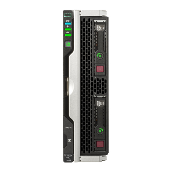
Component identification Front panel LEDs and buttons Item Description Status UID LED Solid blue = Activated Flashing blue (1 Hz/cycle per sec) = Remote management or firmware upgrade in progress Off = Deactivated Health status LED Solid green = Normal Flashing green (1 Hz/cycle per sec) = iLO is rebooting Flashing amber = System degraded Flashing red (1 Hz/cycle per sec) = System critical... -
Page 59: Front Panel Components
iLO reboot is in progress.*Facility power is not present, power cord is not attached, no power supplies are installed, power supply failure has occurred, or the power button cable is disconnected. Front panel components Item Description Drive bay 1* Drive bay 2* External USB 3.0 connector (behind the serial label pull tab) Serial label pull tab Compute module handle release latch... -
Page 60: Hot-Plug Drive Led Definitions
Item Hard drive/SSD bay uFF drive bay NVMe drive bay numbering numbering numbering 1 and 101 2 and 102 Hot-plug drive LED definitions Item Status Definition Locate Solid blue The drive is being identified by a host application. Flashing blue The drive carrier firmware is being updated or requires an update. -
Page 61: Sff Flash Adapter Components And Led Definitions
Item Status Definition Removing the drive does not cause a logical drive to fail. Drive Solid green The drive is a member of one status or more logical drives. Flashing The drive is rebuilding or green performing a RAID migration, strip size migration, capacity expansion, or logical drive extension, or is erasing. -
Page 62: Nvme Ssd Components
Item Component Description Drive status LED • Off—The drive is not configured by a RAID controller • Solid green—The drive is a member of one or more logical drives. • Flashing green (4 Hz)—The drive is operating normally and has activity. -
Page 63: System Board Components
System board components Item Description TPM connector System battery Internal USB 3.0 connector Drive backplane connector Processor 1 DIMM slots (12) Processor 2 DIMM slots (12) HPE Smart Storage Battery connector Mezzanine connectors (M1, M2, and M3) Management/power connector System maintenance switch microSD card slot External USB 3.0 connector System maintenance switch... -
Page 64: Mezzanine Connector Definitions
Position Default Function Reserved Off = Power-on password is enabled. On = Power-on password is disabled. S6* ** Off = No function On = Restore default manufacturing settings Off = Set default boot mode to UEFI. On = Set default boot mode to legacy. —... -
Page 65: Dimm Slot Locations
Type C only ICM 3 and 6 * When an NVIDIA Tesla M6 GPU FIO Adapter for HPE Synergy 480 Gen9 Compute Module is installed in mezzanine connector 1, mezzanine connector 2 is not available for additional mezzanine cards. ** When installing a mezzanine option on mezzanine connector 2, processor 2 must be installed. -
Page 66: Components
Components Item Description MicroSD card slot SD1 card SD2 card LEDs Item Description Status Power LED Green: Device is on and at least one microSD card is functioning Red: Both microSD cards have failed SD2 LED On: microSD card has failed Off: microSD card is healthy SD1 LED On: microSD card has failed... -
Page 67: Component And Led Identification For Hpe Synergy Hardware
Component and LED identification for HPE Synergy hardware For more information about component and LED identification for HPE Synergy components, see the product- specific maintenance and service guide or the HPE Synergy 12000 Frame Setup and Installation Guide in the Hewlett Packard Enterprise Information Library . -
Page 68: Cabling
Cabling Cabling resources Cabling configurations and requirements vary depending on the product and installed options. For more information about product features, specifications, options, configurations, and compatibility, see the product QuickSpecs on the Hewlett Packard Enterprise website . HPE Smart Storage Battery cabling HPE Smart Array P542D Controller cabling Cabling... -
Page 69: Specifications
Specifications Environmental specifications Specification Value Temperature range* — Operating 10°C to 35°C (50°F to 95°F) Non-operating -30°C to 60°C (-22°F to 140°F) Relative humidity (noncondensing)** — Operating 10% to 90% @ 28°C (82.4°F) Non-operating 5% to 95% @ 38.7°C (101.7°F) Altitude†... -
Page 70: Acronyms And Abbreviations
Acronyms and abbreviations enterprise mainstream (HPE SSD endurance class) electrical nonmetallic tubing enterprise value (HPE SSD endurance class) Integrated Lights-Out Integrated Management Log keyboard, video, and mouse midline (HPE Midline drive family) POST Power-On Self-Test serial attached SCSI SATA serial ATA small form factor serial, USB, video Trusted Platform Module... -
Page 71: Documentation Feedback
Documentation feedback Hewlett Packard Enterprise is committed to providing documentation that meets your needs. To help us improve the documentation, send any errors, suggestions, or comments to Documentation Feedback (docsfeedback@hpe.com). When submitting your feedback, include the document title, part number, edition, and publication date located on the front cover of the document.
Need help?
Do you have a question about the Synergy 480 Gen9 and is the answer not in the manual?
Questions and answers