Advertisement
Quick Links
Advertisement

Related Manuals for Extreme Flight focke-wulf FW-190A


Summary of Contents for Extreme Flight focke-wulf FW-190A
- Page 1 Focke-Wulf FW-190a Copyright 2016 Extreme Flight RC...
- Page 2 AcesHigh have worked hard to create a model that pays great tribute to the performance of the real thing. As part of the Extreme Flight family, we have combined the highest level of aircraft manufacture with new technology, and the results are fantastic.
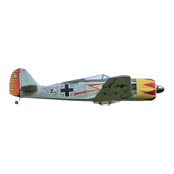
- Page 3 “Black Eight” - Willi Maximowitz Willi was more into bombers. Credited with 27 victories, 15 of them were four engine bombers. At least one of these bombers (though he claimed a second also) was taken by, get this, ramming it. April 20 1945, Willi failed to return from a combat mission.
- Page 4 Extreme Flight RC, Ltd. guarantees this kit to be free of defects in materials and workmanship for a period of 30 DAYS from the date of purchase. All warranty claims must be accompanied by the original dated receipt. This warranty is extended to the original purchaser of the aircraft kit only.
-
Page 5: Tips For Success
Tips for Success Before starting assembly, take a few minutes to read the entire instruction manual to familiarize yourself with the assembly process. Use a fresh bottle of thin CA with a fine glue tip when attaching the CA hinges. This will ensure that the proper amount of CA wicks into the hinge and surrounding balsa wood and creates a proper bond between the wood and hinges. - Page 6 LET’S BEGIN !!! Hinging the aileron. Remove the aileron, and place some pins into the center of the hinges. This will prevent the hinges from pushing into only one side of the control surface of the wing. Insert the aileron into the wing, and remove the pins.
- Page 7 Insert hinge into the flap. Wipe with denatured alcohol (methylated spirits) to clean away any excess glue and ensure the hinge moves freely. With all hinges glued into the flap surface, repeat the hinge gluing steps for the other side and insert the flap into the wing.
- Page 8 Note: The curved horns are for the ailerons, and the triangle shaped horns are for the flaps. Mix up some epoxy, and use a tool/stick to pace into the holes of the control surface. Wipe some epoxy onto the sanded tab area of the horn, and insert into control surface.
- Page 9 Center your servo using your radio. Place a servo arm on the servo so that at center it sticks out of the hole at right angles to the servo mount door. Run the servo wire through the wing and screw into place. 1 inch/25mm arm is ideal for ailerons.
- Page 10 Apply a drop of thin CA, or blue thread locker, to all nuts of the control system. One at a time, remove screws from the landing gear door and apply a small drop of thread locker. Using a 2.5mm hex driver, remove the mounting screws from the retract units.
- Page 11 Using a 1.5mm hex driver, remove the set screw from the base of each side of the landing gear. Place a drop of blue thread locker to the set screw and screw back into place. Screw landing gear back into place.
- Page 12 Using 1.5mm hex driver, remove the wheel collar from the landing gear, and remove the wheel. Using a pair of pliers, remove the landing gear axle, and add a drop of blue thread locker. Screw axle back into place, mount wheel and wheel collar. And yes, the set screw on the wheel collar could also use some blue thread locker ...
- Page 13 Locate the rudder hardware pack. Rough up the tab of the control horn with coarse sand paper. As with the ailerons, apply epoxy glue into the hole of the rudder and the tab of the control horn. Slot into place, and clean away any excess glue with a paper towel soaked in denatured alcohol (methylated spirits).
- Page 14 Slide the stabilizer into place, and use a rule or tape measure to make sure it is centered. To make sure that the stabilizer is straight, measure from corner of the stabilizer to the rear of the canopy bay. Do this on each side and adjust the angle of the stabilizer until even.
- Page 15 Deflect the elevator, and add a couple of drops of thin CA to the hinges. Locate the “Stab” hardware pack. Sand the tab of the control horn with coarse sand paper. Apply epoxy to the hole and tab of the control horn, and insert into the slot.
- Page 16 Locate the pushrod and ball link hardware. Note: The longer pushrod is for the rudder side, and the shorter pushrod is for the elevator. Screw a ball link onto the shorter rod for the stabilizer, and slide into the fuselage. Using the 2mm screw and nut, bolt the pushrod to the control horn.
- Page 17 Position the bracket so that the center of the pivot is over the hinge line as shown. Screw the bracket into place with the two screws provided. Screw the steering arm into the base of the rudder as shown. Remove the tail wheel bracket and add a drop of thin CA to each screw hole.
- Page 18 Using a drop of thread locker on the bolts, bolt the motor to the firewall using a 3mm hex driver. Connect the motor to your speed control, battery and radio system to test the direction of the motor. Thread the battery wires and radio wire through the former.
- Page 19 Available where all awesome airplanes (Extreme Flight) are sold With some low adhesive painters tape, mark the location of screws for the cowling as shown (the center of the tabs).
- Page 20 Make sure that the machine gun slots are in line with the top of the fuselage. Drill the holes for the screws through the cowling, and screw in the screws with a philips head driver. Remove the screws and the cowling to add a drop of thin CA to the screw holes.
- Page 21 As a reference, add a piece of tape in line with the rear of the canopy insert. Along the corner, cut off the front and back of the canopy insert. Cut off the sides of the insert along the tape and the corner of the insert.
- Page 22 Locate the seat piece, and apply plastic compatible adhesive (a contact adhesive is being shown here, applying glue to the seat as well as the rear of the cockpit area). The seat glued in place. Slide the insert into the canopy as shown.
- Page 23 Completed canopy with insert details. The final step, wing attachment. Slide the wing halves onto the carbon fiber wing tube, making sure to connect the landing gear controller. Locate the covered ply plate and the wing attach bolts. In the “Main Wing”...
-
Page 24: Center Of Gravity
Setup Center of Gravity The recommended range for maiden flight is 4” to 4.25” (100mm – 18mm) measured from the leading edge where the wing meets the fuselage. For convenience, a handy way to balance the plane without the canopy is the photo below: hang the model from the side rails using a scrap piece of wood cut to length. -
Page 25: Final Steps
Flaps Mid Flap: ~25 degrees – 4% down elevator mix Full Flap: ~50 degrees – 7% down elevator mix Flying with flaps Because an elevator mix is required for level flight with the flaps down, it is advised to not use the flaps for the maiden flight.
Need help?
Do you have a question about the focke-wulf FW-190A and is the answer not in the manual?
Questions and answers