
Related Manuals for Extreme Flight LEGACY AVIATION 100" Turbo Bushmaster 35-38CC/12S


Summary of Contents for Extreme Flight LEGACY AVIATION 100" Turbo Bushmaster 35-38CC/12S
- Page 1 TURBO 100” BUSHMASTER DESIGNED BY CODY WOJCICK Copyright 2023 Extreme Flight RC...
- Page 2 ALL liability for the use of this product, please return it to the place of purchase immediately. Extreme Flight RC, Ltd. guarantees this kit to be free of defects in materials and workmanship for a period of 30 DAYS from the date of purchase.
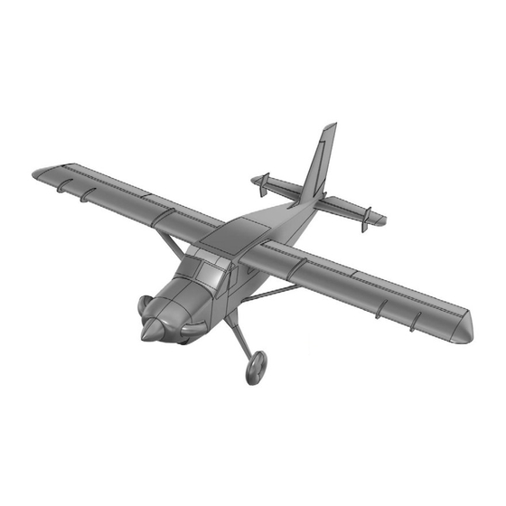
- Page 3 100” TURBO BUSHMASTER 35-38CC / 12S 1978 Bushmaster 100in. Fuselage Length: 1978mm/77.9 in. Wing Span: 2540mm /100 in. WING AREA: 79dm²/1224.5 sq.in. Wing tube:22x965mm/6x320mm Stab tube:13x360mm/6x160mm Main wing incidence:0.5 deg Stab incidence:0 deg Right thrust:2 deg Up/Down thrust:0 deg 2540...
- Page 4 Qty. 4 Extreme Flight 1.5 inch single servo arms (tapped 3mm) for ailerons Qty. 3 Extreme Flight 1.5 inch single servo arms (tapped for 3mm) for elevators and rudder QTY 1 Metal gear mini servo for tailwheel w/ Extreme Flight mini servo arm 1.25”...
- Page 5 A few tips to ensure success: 1. We are very pleased with the level of craftsmanship displayed by the builders in our factory. Through hundreds of grueling test flights containing maneuvers that no aircraft should be subjected to, our prototypes have remained rigid and completely airworthy.
- Page 6 Locate the carbon fiber landing gear and the Main Wheel hardware pack. The gear has a front, and a back. To identify the front, note that the gear sweeps slight forward when installed. Use 4 screws and washers with loctite to install the landing gear as shown. Locate the gear “cuff ” fairings.
- Page 7 Attach the wheel axles to the landing gear by tightening the locking nuts. Slide on the wheels, and the wheel spacers. Note the axles have flat areas to accept the wheel collar set screws. Put loctite on the set screw, then install and tighten the wheel collars. Locate the tailwheel and hardware bag. Using loctite, mount the tailwheel to the fuselage using three screws as shown.
- Page 8 Assemble the tailwheel pushrod with the nylon ball link ends as shown. Remove the covering over the tail- wheel steering servo mount location as shown. Install the servo wire extension onto the servo and mount the servo. Install the pushrod between the servo arm and the tailwheel arm with 2mm screws, washers, and locking nuts.
- Page 9 Locate the stab/rudder (it is pre-hinged for you), its hardware pack, and your servo, wire extesion, and servo arm. Remove the wood tab on the bottom of the stab as shown. Locate the control horns. Sand them lightly as shown in the area which will be glued. Assemble the plastic ball links onto the pushrods, we use a cordless drill to assist.
- Page 10 Remove the covering in the area between the slots on the rudder as shown. Test-fit the horn assembly into the slots. It should be tight, but should go in with moderate force. You may need to clean out the slots with the hobby knife. Place epoxy glue into the slots and onto the horns. Push the horns into the slot, seat it firmly.
- Page 11 Locate the rudder extension piece which mounts to the fuselage. Check its fit as shown. Glue to the fu- selage with epoxy and use masking tape to hold the position while it cures. Now is a good time to cen- ter your servos using your radio system or a servo tester.
- Page 12 Install your servo arms, use loctite on the arm screws. Attach the pushrod to the arm with screw and washers, use loctite or a locking nut for safety. Because the pushrod has one left, and one right hand threads, you can adjust the length of the pushrod by rotating it. Adjust the length of the pushrod so that the servo arm is 90 degrees as shown when the rudder is centered.
- Page 13 Locate the horizontal stabs/elevators. These are pre-hinged for you. Install the control horns exactly as you did on the rudder, and assemble the pushrods in the same way. Locate the fins for the stabs and install with screws and loctite as shown. TURBO B BU U SH M A A S S T T ER...
- Page 14 Locate the elevator servos, make sure they are centered. Plug them into the elevator wire extensions, be- cause we expect to remove the stabs for transport, we use a servo plug lock on the connection. Using the front and rear carbon stab tubes, install the stabs and engage the stab locks as shown. Install the servo arm with loctite and attach the pushrod using loctite or locking nuts.
- Page 15 Locate the wings and Main Wing hardware pack. The wings are pre-hinged for you. Asemble the ai- leron and flap pushrods. All 8 control horns are identical. Sand and install them just as you did the rudder and elevator horns. Attach your servo wire extension to the aileron aervo and feed through the wing.
- Page 16 Locate the two carbon wing tubes and slide into the fuselage as shown. Locate the wing strut brackets.Cut a slit in the covering to allow the fuselage-side bracket to protrude. Loosely install the wing side and fuse- lage side brackets for the wing struts with loctite, but do not fully tighten. Slide the wings on the tubes all the way and close the wing latches inside the fuselage.
- Page 17 When the wings are removed from the airplane, the struts lay flat against the wing and will fit into the wing bags for transport. The long axle screw on the wing-side strut mount should be locked in place with a small drop of CA under the screw head. The firewall of your aircraft is marked with two common bolt pattern for engine/motor mounting.
- Page 18 The distance between the firewall surface and the front of the cowl on your bushmaster is approximately 163mm. This matches the length of common gas engines with their includ- ed standoffs/spacers. We do not want a tight spinner-to-cowl fit on the Bushmaster, leave 3-4mm for cooling air to enter the cowling.
- Page 19 If using a gas engine, install onto the firewall, trimming the firewall as necessary to fit the carburetor. Use large diameter washers on the firewall to spread the load of the engine mounting screws, on front and back if possible. Use loctite to install the screws. Locate the “Thottle” hardware pack. Inside is a pushrod with one threaded end.
- Page 20 Mount the ignition unit to the side of the motor box using adhesive velcro, velcro straps, and cushioning foam if desired. To cut the bottom of the cowl for clearance and cooling, it is helpful to make a template from heavy paper or card stock or thin plywood. Use this template to mark the cowl before cutting. Wear eye and lung protection when cutting the fiberglass cowl.
- Page 21 If you are using either of the recommended brushless motors, the recommended Blazing Star stand- offs can be easily adjusted for proper length by adding or subtracting sections. Install with loctite. Install the turbo exhaust pipes with a screw and loctite. TURBO B BU U SH M A A S S T T ER...
- Page 22 If you are using a tuned pipe or canister exhaust on a gas engine, remove the panel on the bottom of the F1 former. We also recommend removing this panel if you are running an electric power system. Only if you are running a gas engine with stock muffler should you leave this panel in place. If you are using a tuned pipe or canister, we have included an exhaust mount with vibration-isolators which screws into the fuselage.
- Page 23 Balance your aircraft. We recommend balancing it so that it simply hangs level when lifted by the main wing tube. This is our favorite balance point for all types of flying. Set your control throws accoring to the setup sheet in the front of this manual. Test your power system in a safe manner on the ground, and range-check your radio system.
Need help?
Do you have a question about the LEGACY AVIATION 100" Turbo Bushmaster 35-38CC/12S and is the answer not in the manual?
Questions and answers