
Related Manuals for BIO RAD Gel Doc 2000ChemiDocChemiDoc XRS


Summary of Contents for BIO RAD Gel Doc 2000ChemiDocChemiDoc XRS
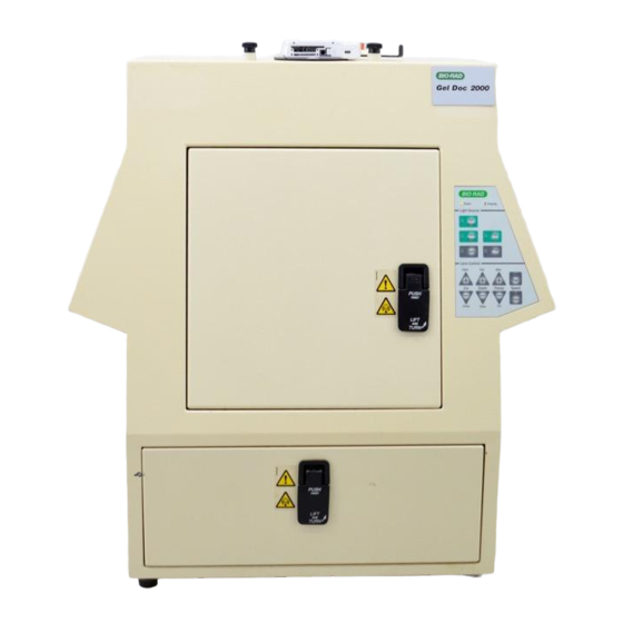
- Page 1 Gel Doc 2000 ChemiDoc ChemiDoc XRS Hardware Instruction Manual (Includes Universal Hood Catalog Number 170-8126) P/N MI1708126AA Rev.C...
- Page 2 Important Please read these instructions before operating the Universal Hood to become familiar with its operation. Note: This instrument is suitable for research use only. It must be used, therefore, only by specialized personnel that know the health risks associated with UV radiation and with the reagents that are normally used with this instrument.
- Page 3 Regulatory Notice IMPORTANT: This Bio-Rad instrument is designed and certified to meet ENC1010, the internationally accepted electrical safety standards and EMC regulations. Certified products are safe to use when operated in accordance with the instruction manual. This instrument should not be modified or altered in any way.
- Page 4 General Precautions Please read the instruction manual carefully. • The instrument must be used only for the intended purpose of gel documentation in research • laboratories. When power is applied to the Universal Hood the source must be a grounded AC outlet. •...
-
Page 5: Table Of Contents
TABLE OF CONTENTS: SECTION 1 INTRODUCTION ......................5 1.1 C ......................6 OMPUTER EQUIREMENTS 1.2 PC ..............................6 1.3 M ............................ 6 ACINTOSH SECTION 2 IMPORTANT SAFETY INFORMATION ..............7 2.2 P : ..................... 7 OWER AFETY NFORMATION SECTION 3 PRODUCT DESCRIPTION................... 7 3.1 CCD C .......................... -
Page 6: Section 1 Introduction
Section 1 Introduction The Bio-Rad Gel Doc 2000, ChemiDoc and the ChemiDoc XRS Gel Documentation systems are easy-to-use, high-performance systems. They use a CCD camera to capture images in real time, which allows you to more accurately position and focus the image. While using Bio-Rad TDS Quantity One software, acquired images can be optimized, annotated, analyzed, and printed to a video printer or your local or network printer. -
Page 7: Section 2 Important Safety Information
Section 2 Important Safety Information 2.1 IMPORTANT NOTICE Use of the Universal Hood involves UV illumination. Proper precautions must be taken to avoid eye and skin exposure to the UV radiation. This instrument is meant for use only by specialized personnel that know the health risks connected to UV radiation and to the reagents that are normally used with this instrument. -
Page 8: Section 3 Product Description
Section 3 Product Description 3.1 CCD Camera A CCD camera is placed on top of the Universal Hood for capturing images. The camera comes with a Motorized Zoom Lens (MZL) that allows a remote adjustment of the lens control functions viz. - Page 9 Part # Descriptions 170-8100/170-8615 Gel Doc 2000 System PC/MAC RS-170 170-8101/170-8616 Gel Doc 2000 System PC/MAC CCIR 170-8126 Universal Hood 100/230 Vac (includes): Universal Hood with Bracket, UV Shield, Spare fuses, Instruction Manual Power cable 170-7541/7540 PCI Digitizing card, RS170/CCIR 170-7546 Integrating Cable 170-8120...
-
Page 10: Section 4 Getting Started
Section 4 Getting Started 4.1 Selecting the Location of the Universal Hood Since the Universal Hood has a complete fluorescence and chemiluminescence darkroom, it can be placed on any bench top. You should place the hood near the computer with the software that will control it. -
Page 11: Assembling The Ccd Camera
4.2.2 Assembling the CCD camera Gel Doc 2000 RS-170/CCIR Camera (170-7951/170-7952) a) Carefully take the CCD camera assembly out of the box and hold the camera so that the two locking holes are facing you. b) Place one plastic black screw into the rear flat side of the MZL. c) Insert the CCD camera into the bracket from the open left side and fix it with one or two black screws. - Page 12 Please refer to the instructions included in Appendix B for a complete description of the cables connection. ChemiDoc XRS Camera: (170-8078) NOTE: For this installation you will require Camera Bracket Assembly 1708079. a) Carefully take the Camera bracket assembly out of the box and set it on a clean table as shown below: Lens Center adjustment screw...
- Page 13 f) Now adjust the camera position such that the following conditions are met: i. The lens body is flush against the rubber gasket on the adapter plate ii. The lens is well centered in the opening of the adapter plate as shown in the picture. g) It may be required to adjust the black adapter plate on the bracket assembly to center the lens.
- Page 14 Place the Camera + Bracket assembly on top of the Universal Hood. k) Adjust the bracket assembly such that the lens is centered in the opening of the hood as seen from inside the hood. Center the lens in the opening of the hood as viewed from inside of the hood l) Secure the bracket to the hood at to the four studs located on top of the hood by using four black knobs and washers.
-
Page 15: Installing The Pci Digitizing Card
m) A properly installed ChemiDoc XRS Camera + Bracket assembly on a universal hood are shown in the following below: ChemiDoc XRS System Please refer to the instructions included in Appendix C for a complete description of the cables connection. 4.2.3 Installing the PCI Digitizing Card NOTE : When installing the PCI Digitizing Card for the ChemiDoc XRS, please install the TDS... -
Page 16: Installing The Software
Connect the Camera Controller Cable to the PCI card 4.2.4 Installing the software Please refer to your software manual and release notes for proper software installation. 4.2.5 Connecting the cabling harnesses The connections are different if you are installing a Gel Doc 2000, ChemiDoc or a ChemiDoc XRS camera. -
Page 17: Installing The Optional 17 Mm Or 25 Mm Wide-Angle Lenses (Chemidoc Xrs Only)
4.2.7 Installing the Optional 17 mm or 25 mm wide-angle Lenses (ChemiDoc XRS only): This installation guide covers installation of the optional lenses to the ChemiDoc XRS system (only). The following catalog numbers are covered under this category: 1708072 Lens f 0.95, 25 mm, Wide angle ii. - Page 18 Place the Light Seal in the round slot on the Make sure that the hard side of the donut is facing bottom side of the bracket outward 7. Place the bracket assembly on a hard surface and attach the Camera with the wide-angle lens with the black washer and the thumbscrew.
-
Page 19: Description Of Functions And System Initialization
Focusing Ring Iris Control Ring 12. When using this Lens for most sensitivity in Chemi Imaging, make sure that the Iris is opened all the way. 4.3 Description of Functions and System Initialization 4.3.1 Control panel The front membrane touch pad control panel of the Universal Hood allows full control of all the functions including the lens operations, the UV, Epi and White Light (optional) illumination in the darkroom cabinet. - Page 20 Light source section The Epi-White button controls the white Epi-illumination light. Press the button to turn on Epi illumination; press the button again to turn it off. Epi-illumination will automatically turn off after 15 minutes, unless the hold button is activated. When the UV transilluminator switch is activated, the white-white light is automatically turned off.
- Page 21 Camera Lens and Filters The MZL functions are operated from the membrane touch pad or through the buttons present in the acquisition window in the software. To see buttons in the software acquisition window, it is necessary to connect the Universal Hood with a null modem cable. (170-7963 or 1707964 – MAC or PC) from the COM1 to the Serial port of the hood itself.
-
Page 22: Initial Test
Picture of the Sliding Filter from the inside 4.3.2 Initial test Before starting the initial test please make sure that: 1. The software and the digitizing board are installed properly. 2. The cabling harness is connected properly. (See Appendix A, B or C ) Please follow the procedure in the table to ensure that the Universal Hood is functioning properly. - Page 23 Initial test for the camera and lens assembly Procedure (For Gel Doc 2000/ChemiDoc/ChemiDoc XRS systems) 1. Press the Epi-Illumination Key. 2. Open the door and check if light is on. 3. Place the focusing target on the UV transilluminator. 4. Start the image acquisition software in your PC (TDS Quantity one). 5.
-
Page 24: Aligning The Camera And Bracket (This Applies To All Systems)
NOTE: No lights should be turned ON. Please allow approximately 1 hour for the Dark Reference acquisition . 1. After the “Dark Reference” acquisition is over the system will be ready to operate 2. Turn ON the Epi-White lights using the Epi-White touch pad button 3. - Page 25 7. Use the zoom button on the control panel to zoom in and out on the image. 8. When the camera, bracket, and target are correctly aligned, the center of the target will stay in the center of the image throughout the zoom range. 9.
-
Page 26: Section 5 Operation Of The Universal Hood
Section 5 Operation of the Universal Hood 5.1 Operating the unit The Gel Doc 2000, ChemiDoc and ChemiDoc XRS Systems are easy-to-use instruments. In the TDS Quantity One Acquisition screen on your computer, select Live/Focus mode and adjust your image position, size, focus, and intensity using the lens controls. After the image is optimized, capture the image. - Page 27 9. See picture below: 10. Next you will be prompted to remove your sample from the transilluminator and place the Fluorescent Reference Plate on the platen for UV illuminated images. For White Light Illumination the white light transilluminator or the UV conversion screen is used to collect the reference Flat Fielding image.
-
Page 28: Cutting Gels
13. The system will automatically acquire a reference image and a flat-fielded Image of the sample will be generated for you to save and analyze. 14. For additional details on Flat Fielding please refer to the Software Manual. You may also click on the HELP button in the Software window for a detailed description of the Software functionality. -
Page 29: Section 6 Trouble Shooting
Section 6 Trouble Shooting Problem Possible Cause Solution • Aperture is closed. • Open the aperture. Image is not visible on the monitor • Incorrect monitor • See your computer settings manual • Wrong cable • See Appendix A or B connections. - Page 30 Problem Possible Cause Solution • The sample is too • Close the IRIS using the ChemiDoc XRS image will not Auto expose bright and saturates IRIS control until Auto the image at the expose is possible. minimum possible exposure • Aperture is open too •...
-
Page 31: Section 7 Accessories And Replacement Parts
Section 7 Accessories and Replacement Parts 7.1 Accessories Part number Description 100-1359 Knob Knurled Head M6 (4) 100-1361 Lamp, UV B (302 nm – 1 each for Gel/ChemiDoc/XRS) 100-1370 UV TR Starter St151 (3 each) 100-1381 Lamp, Epi-illumination, 11 W PI1182 100-1397 UV Transilluminator Lid (Includes filter glass) 100-1399... - Page 32 170-8077 Filter, 440BP70 170-8078 Camera w/MZL, ChemiDoc XRS 170-8079 Camera Bracket Assembly, ChemiDoc XRS 170-8080 Kit, Accessory, Chemi Doc XRS 170-8081 Kit, Filter, Amber, 62 mm 170-8082 Adapter, filter, 58-62 mm, Gel Doc 2000/ChemiDoc/ChemiDoc XRS 170-8092 Upgrade kit, RS170, MZL, PC (Gel Doc 2000 to ChemiDoc) 170-8093 Upgrade kit, CCIR,, MZL, PC(Gel Doc 2000 to ChemiDoc) 170-8094...
-
Page 33: Section 8 Maintenance And Part Replacement
Section 8 Maintenance and Part Replacement: This section covers the replacement of parts in the Universal Hood. 8.1 Epi-illumination lamps replacement The lamps are located behind the two panels on each side (left and right) of the internal side of the hood. -
Page 34: Uv Transilluminator
This unit is protected by 2 fuses 5X20 mm 2A Slow Blow. The fuses are located in the rear left side in a fuse holder. See above picture. 1. Unplug the main power cable from the power entry module outlet. 2. -
Page 35: Starter Replacement (P/N 100-1370)
8.3.2 Starter replacement (P/N 100-1370) Turn off the power. • Disconnect the power cord. • Remove the four screws located on the side of the instrument. • Remove the lid. • Place it down on its backside on a non-abrasive surface. •... -
Page 36: Appendix A: Gel Doc 2000 System Installation
Appendix A: Gel Doc 2000 System installation The following appendix gives additional information to use the Universal Hood in the Gel Doc 2000 configuration. Connecting the cabling harnesses a) Carefully take the CCD camera assembly out of the box and hold the camera so that the two locking holes are facing you. -
Page 37: Appendix B: Chemidoc System Installation
Appendix B: ChemiDoc System installation The following appendix gives additional information to use the Universal Hood in the ChemiDoc configuration. Connecting the cabling harnesses a) Carefully take the CCD camera assembly out of the box and hold the camera so that the two locking holes are facing you. -
Page 38: Appendix C: Chemidoc Xrs System Installation
Appendix C: ChemiDoc XRS System installation a. Connect the Motorized zoom lens cable to the 5-pin din connector labeled LENS on the side panel of the hood. (See picture below) 5-Pin Din connector labeled LENS Serial port DB25 to connect a null modem serial cable from PC Com1 port. - Page 39 d. Connect the provided Serial Cable to the 9- pin DIN/8 pin round serial connector on the PC/MAC and the other end of the 25 pin serial connector on the Universal Hood. e. In case of a MAC with a USB, connect the optional (170-7959) USB to Serial adapter (not included) with a USB cable to the MAC and then connect the 8 pin round connector of the MAC serial cable (1707963) between the adapter and the Universal Hood.
-
Page 40: Appendix D: Chemidoc Xrs Pci Digitizing Card Driver Installation
Appendix D: ChemiDoc XRS PCI Digitizing Card Driver Installation: CAUTION: Make sure that Card is NOT installed in the PC The following procedure describes how to install the drivers that are provided with your TDS Quantity CD ROM. a. Insert TDS Quantity One CD into the CD ROM drive of the PC. It will go into AUTO RUN mode and the following window will open: b. - Page 41 Click on “Quantity One” folder and the following window will open: d. Select “ChemiDoc XRS Drivers” folder and the following window will open: Double click on “PVCamSetup.exe” icon and follow direction. This self installing utility will install the appropriate drivers on your PC. Next install the PCI Card into the PC.
-
Page 42: Appendix E: Technical Specifications
Appendix E: Technical Specifications Model Gel Doc 2000 ChemiDoc ChemiDoc XRS Application Chemiluminescence Fluorescence Chemifluorescence Colorimetric/Densitometry Gel Documentation Isotopic Imaging Hardware Specifications 28 x 36 cm 28 x 36 cm 28 x 36 cm Maximum Sample Size Maximum Image Area 25 x 26 cm 25 x 26 cm 25 x 26 cm...
Need help?
Do you have a question about the Gel Doc 2000ChemiDocChemiDoc XRS and is the answer not in the manual?
Questions and answers