
Related Manuals for BIO RAD Gel Doc XR 170-8170


Summary of Contents for BIO RAD Gel Doc XR 170-8170
-
Page 1: Hardware Instruction Manual
Gel Doc ChemiDoc 170-8170 170-8070 170-8171 170-8071 Hardware Instruction Manual MI170-8062BB Rev.G... - Page 2 The Gel Doc XR, and Chemi XRS are warranted against defects in materials and workmanship for 1 year. If any defect occurs in the instrument during this warranty period, Bio-Rad Laboratories will repair or replace the defective parts at its discretion without charge. The following defects, however, are specifically excluded: •...
- Page 3 2. Void the regulatory certifications. 3. Create a potential safety hazard. NOTE: Bio-Rad Laboratories is not responsible for any injury or damage caused by use of this instrument for purposes other than those for which it is intended, or by modifications of the instrument not performed by Bio-Rad Laboratories or an authorized agent.
- Page 4 General Precautions Please read the instruction manual carefully. • The instrument must be used only for the intended purpose of gel documentation in research • laboratories. The instrument must be connected to a power source line which MUST BE grounded and •...
-
Page 5: Table Of Contents
TABLE OF CONTENTS HARDWARE INSTRUCTION MANUAL ........................1 SECTION 1 INTRODUCTION.............................7 1.1 C ............................7 OMPUTER EQUIREMENTS 1.2 PC ...................................7 1.3 M ................................7 ACINTOSH SECTION 2 IMPORTANT SAFETY INFORMATION.....................8 2.1 I ..............................8 MPORTANT OTICE 2.2 P ...........................8 OWER AFETY INFORMATION SECTION 3 PRODUCT DESCRIPTION ........................9 3.1 CCD C ............................9 AMERA AND... - Page 6 ALSO READ THE RELEASE NOTES FILE FOR LAST MINUTE UPDATES FOR THE SOFTWARE..40 APPENDIX D: PCI CARD INSTALLATION......................41 Gel Doc XR – PC:..............................41 Gel Doc XR - Mac: ..............................41 ChemiDoc XRS- PC:............................41 Installing the PCI Digitizing Card ..........................41 APPENDIX E: TECHNICAL SPECIFICATIONS ....................42 Page 6 of 42...
-
Page 7: Section 1 Introduction
Section 1 Introduction The Bio-Rad Gel Doc XR, and the ChemiDoc XRS Gel Documentation systems are easy- to-use, high-performance systems. They use a CCD Camera to capture images in real time, which allows you to more accurately position and focus the image. While using Bio-Rad Quantity One... -
Page 8: Section 2 Important Safety Information
Section 2 Important Safety Information 2.1 Important Notice Use of the Gel Doc XR, and ChemiDoc XRS involves UV illumination. Proper precautions must be taken to avoid eye and skin exposure to the UV radiation. This instrument is meant for use only by specialized personnel that know the health risks associated with UV radiation and the reagents that are normally used with this instrument. -
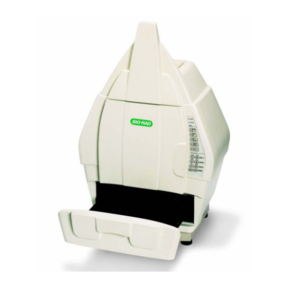
Page 9: Section 3 Product Description
The Universal Hood II has a three position Filter Slider that offers the flexibility of using two different emission filters for fluorescence applications as well as the ability to image chemiluminescence samples (no filter). Bio-Rad Laboratories offers a selection of filters and illumination sources. Standard Filter: Comes with each system. -
Page 10: Pci Interface Cards
Note: Read and follow the instructions in Appendix C and D prior to installing Quantity One software. 3.5 Printer (Optional) For your convenience, Bio-Rad offers an optional USB printer for use with the Gel Doc XR and ChemiDoc XRS: Sony UPD895 (recommended for both the systems) 170-8066 3.6 Packaging... - Page 11 Part # Descriptions 170-8170/170-8171 Gel Doc XR System PC/Mac 170-8062 Universal Hood II W/TLUM 100/240 Vac Gel Doc XR Camera and Cable w/MZL 170-8172 Gel Doc XR Fire Wire card (PC System only) 170-8173 170-8080 Kit Accessory, Universal Hood II 170-7964/7963 Cable, Serial, MZL, PC/Mac Quantity One ...
-
Page 12: Section 4 Getting Started
Section 4 Getting Started 4.1 Selecting a Location The Gel Doc XR and ChemiDoc XRS systems can be placed on any bench top. The best position is near the computer where Quantity One will be operating. Remember to leave space to easily access the power switch on the Universal Hood II, which is located at the rear bottom left side of the enclosure 4.2 Assembling the System... -
Page 13: Assembling The Ccd Camera
4.2.2 Assembling the CCD Camera Gel Doc XR a) Place the Camera on the bench so that the two tripod mount holes are facing you. b) Using one of the two knurled screws and washers attach the Gel Doc bracket to the Camera as shown in the picture below. - Page 14 Upon completion of the Camera installation, refer to Section 4.2.3 and Appendix A for a complete description of the cable connections. ChemiDoc XRS a) Place the Camera on the bench so that the locking hole of the tripod mount is facing you. b) Fix the ChemiDoc ...
-
Page 15: Connecting The Cabling Harnesses
Center the lens in the opening of the hood as viewed from inside of the hood e) Fix the Camera bracket to the bracket on the Universal Hood II using the screw, washer and knurled knob. f) Lower the Camera so that the lens fit properly on the gasket of the black adapter ring then tighten the black screw on the tripod mount Upon completion of the Camera installation, refer to Section 4.2.3 and Appendix B for a complete description of the cable connections. -
Page 16: Installing The White Light Transilluminator (Optional)
4.2.4 Installing the White Light Transilluminator (Optional) To install the White Light Transilluminator, open the door to the enclosure and pull the drawer completely toward you. Locate the power cable positioned on the left side (inside of the enclosure) behind the slide of the drawer. Remove the black rubber that covers the banana plug and insert it into the White Light Transilluminator outlet. - Page 17 Setting Up the Lens: 1. Turn off the power to the enclosure and Camera 2. Disconnect the Camera and lens cables 3. Remove the ChemiDoc XRS Camera from the bracket. 4. Remove the existing Motorized Zoom Lens from the Camera by turning the lens counterclockwise.
-
Page 18: Description Of System Function And System Initialization
Focusing Ring Iris Control Ring 9. For imaging of chemiluminescent samples, make sure that the Iris is opened all the way. 4.3 Description of System Function and System Initialization 4.3.1 Control panel The front membrane touch pad control panel of the Universal Hood II allows full control of the Motorized Zoom Lens, UV transillumination, White Epi illumination and White Light transillumination. - Page 19 The Imaging led blinks when you are acquiring an image with the Camera (this function is not present using the Gel Doc XR or ChemiDoc XRS Cameras) indicating integration by the Camera. It also blinks if the computer is turned off. Light Sources The Epi-White button controls the Epi White illumination.
- Page 20 If opening the door or drawer (activating the UV interlock, which turns off the UV), you will need to turn off the Hold button before pressing any other switch. The control panel has a second section that includes the buttons to run all the MZL functions (see the Lens Control Section below).
-
Page 21: System Initialization
Filters: A +1 Diopter is factory installed on the lens. This Diopter should always remain on the lens assembly. An Amber Filter is included in the Accessory Kit. Place the Amber filter in position 1 or 2 of the Filter Slider (See 4.2.1). The Amber filter should be used for fluorescence (UV) and colorimetric (White light) applications. - Page 22 STEP 2: Initialization of the Camera and lens assembly Procedure (for Gel Doc XR/ ChemiDoc XRS systems): 1. Press the Epi-Illumination button. 2. Open the door and determine if lights are on. 3. Place the focusing target on the UV transilluminator. 4.
- Page 23 1. Make sure that all lights in the Universal Hood II are off. 2. Make sure that the Lens Cap is on the lens. This is critical! 3. Power ON the Camera and the Universal Hood II. 4. Wait for 30 minutes for the system to warm up and stabilize 5.
-
Page 24: Aligning The Camera Assembly
Note: No lights should be turned ON. Please allow approximately 30 seconds for the Gel Doc XR and 30 minutes for the acquisition of the Dark Reference files ChemiDoc XRS systems. 1. After the “Dark Reference” acquisition is over the system will be ready to operate. 2. -
Page 25: Section 5 Operation Of The Universal Hood Ii
Section 5 Operation of the Universal Hood II 5.1 Operating the unit The Gel Doc XR and ChemiDoc XRS Systems are easy-to-use instruments. In the Quantity One acquisition window on your computer, select Live/Focus mode and adjust your image position, size, focus, and intensity using the lens controls. - Page 26 9. Next you will be prompted to remove your sample from the transilluminator and place the Fluorescent Reference Plate on the platen for UV illuminated images. For White Light Illumination the White Light Transilluminator or the UV conversion screen is used to collect the reference Flat Fielding image.
- Page 27 10. Remove the sample from the transilluminator. Remove any liquid or residue remaining from the sample platen. Place the Fluorescent Reference Plate on the platen. Make sure that the plate covers the entire glass surface. Close the door and then click on “Continue” in the window shown above.
-
Page 28: Cutting Gels
Note: When using the White Light, you must turn ON the UV Transilluminator after removing the sample. 12. The system will automatically acquire a reference image and a flat-fielded corrected image of the sample will be generated for you to save and analyze. 13. -
Page 29: Section 6 Trouble Shooting
Section 6 Trouble Shooting Problem Possible Cause Solution • Aperture is closed. • Open the aperture. Image is not visible on the monitor • Incorrect monitor • See your computer manual • See Appendix A or B for settings • Wrong cable correct cabling. -
Page 30: Section 7 Accessories And Replacement Parts
Lens,f/0.95, 25mm, wide angle lens (ChemiDoc XRS only) 170-8072 Lens,f/0.95, 17mm, wide angle lens (ChemiDoc XRS only) 170-8073 170-8068 Shield, UV, Universal Hood II 170-3759 Bio-Rad fluorescent Ruler 170-3760 Gel Cutter Ruler 170-7813 Sample Holders for gels Fluorescent Reference Plate (ChemiDoc XRS only) 170-8008... - Page 31 100-2784 UV transilluminator Lid (Includes filter glass) 100-2785 Universal Hood II Right Shield Epi-illumination (Lid complete) 100-1948 Universal Hood II Opal Filter Epi-illumination (w/o metal frame) 100-2786 Universal Hood II Left Shield Epi-illumination (Lid complete) 100-2787 Universal Hood II Screw Feet (4) 100-1951 Fuse T 2 A –...
-
Page 32: Section 8 Maintenance And Part Replacement
Section 8 Maintenance and Part Replacement This section covers the replacement of parts in the Universal Hood II. 8.1 Epi-illumination lamp replacement The lamps are located behind the two panels on each side (left and right) of the internal side of the hood. -
Page 33: Uv Transilluminator
This unit is protected by 2 fuses 5X20 mm 2A Slow Blow. The fuses are located in the rear left side in a fuse holder. See above picture. 1. Unplug the main power cable from the power entry module outlet. 2. -
Page 34: Starter Replacement (P/N 100-1370)
Lamp replacement Starter replacement 8.3.2 Starter replacement (P/N 100-1370) Turn off the power. • Disconnect the power cord from the Universal Hood II. • Remove the four screws located on the left/right sides of the drawer. • Remove the cover with the UV filter by sliding it forward. •... -
Page 35: Appendix A: Gel Doc Xr System Cable Configuration
Appendix A: Gel Doc XR System Cable Configuration Connecting the cabling harnesses a) Locate the Fire Wire cable. Connect one end of the Fire Wire cable connector to the Fire Wire connector on the Camera and connect the other end to the Fire Wire connector on the PC/Mac b) The Camera power supply cable should be plugged into the CCD Camera PWR connector. -
Page 36: Appendix B: Chemidoc Xrs System Cable Configuration
Appendix B: ChemiDoc XRS System Cable Configuration Connect the motorized zoom lens cable (which is permanently attached to the lens) to the MZL Extension Cable and then to 5-pin din connector labeled LENS on the connector panel of the hood. b. -
Page 37: Appendix C: Installing Software And Drivers
Appendix C: Installing Software and Drivers Gel Doc XR and ChemiDoc XRS- PC: CAUTION: You must install the drivers BEFORE installing the PCI card. a. Insert the Discovery Series CD into the CD ROM drive of the PC. It will go into AUTO RUN mode and the following window will open: a. - Page 38 c. Click the Driver feature (ChemiDoc XRS/VersaDoc or Gel Doc XR) and select “Will be installed on local hard drive.” from the list: d. Click “Next” to complete the installation. Note: If the Windows Device Manager detects a conflict, it may be necessary to move the PCI card to a different slot to avoid conflict with an existing card in the PC.
-
Page 39: Gel Doc Xr And Chemidoc Xrs- Mac
Gel Doc XR and ChemiDoc XRS- Mac: a. Insert “The Discovery Series” software CD into the CD ROM drive of the PC. The CD will show up on the Apple Desktop as an Icon b. Double click on the CD icon the following window will open c. -
Page 40: Also Read The Release Notes File For Last Minute Updates For The Software
d. From the pull down menu, select “Custom Install”. c. Select the Driver you want to install. If you have not yet installed the application, be sure to select that as well. d. When you have made your selections, click Install to complete the installation. Also read the Release Notes file for last minute updates for the Software Page 40 of 42... -
Page 41: Appendix D: Pci Card Installation
Current Mac systems generally have onboard Fire Wire ports (connectors). The Gel Doc XR Camera can be plugged directly into any one of these connectors and Bio-Rad Software interface will be able to communicate with the Camera via this port. -
Page 42: Appendix E: Technical Specifications
Appendix E: Technical Specifications Model Gel Doc XR ChemiDoc XRS Application Chemiluminescence Fluorescence Chemifluorescence Colorimetric/Densitometry Gel Documentation Isotopic Imaging Hardware Specifications Maximum Sample Size 28 x 36 cm 28 x 36 cm Maximum Image Area 25 x 26 cm 25 x 26 cm Trans UV 302, 254, Trans UV 302, 254, Excitation Source...
Need help?
Do you have a question about the Gel Doc XR 170-8170 and is the answer not in the manual?
Questions and answers