Table of Contents
Advertisement
Quick Links
Advertisement
Table of Contents

Related Manuals for IEI Technology PICOe-B650


Summary of Contents for IEI Technology PICOe-B650
- Page 1 PICOe-B650 Half-size PCIe CPU Card MODEL: PICOe-B650 Half-size PCIe CPU Card with LGA1155 32nm Intel® Core™ i7/i5/i3 CPU and Intel® B65 Chipset, DDR3, VGA, USB 2.0, Dual PCIe GbE, SATA 6Gb/s, HD Audio, RoHS Compliant User Manual Page i Rev. 1.01 – 20 November, 2013...
- Page 2 PICOe-B650 Half-size PCIe CPU Card Revision Date Version Changes 20 November, 2013 1.01 Updated Section 5.3.4: SATA Configuration 3 February, 2012 1.00 Initial release Page ii...
- Page 3 PICOe-B650 Half-size PCIe CPU Card Copyright COPYRIGHT NOTICE The information in this document is subject to change without prior notice in order to improve reliability, design and function and does not represent a commitment on the part of the manufacturer.
-
Page 4: Table Of Contents
PICOe-B650 Half-size PCIe CPU Card Table of Contents 1 INTRODUCTION......................1 1.1 I ......................2 NTRODUCTION 1.2 C ......................3 ONNECTORS 1.3 D ....................... 4 IMENSIONS 1.4 D ........................ 5 1.5 T ..................6 ECHNICAL PECIFICATIONS 2 UNPACKING ......................... 8 2.1 A... - Page 5 PICOe-B650 Half-size PCIe CPU Card 3.2.12 Serial Port Connectors (COM 1 and COM 2) ..........26 3.2.13 SMBus Connector ..................27 3.2.14 SPI Flash Connector..................28 3.2.15 TPM Connector....................29 3.2.16 USB Connectors (Internal) ................30 3.3 E ......... 31...
- Page 6 PICOe-B650 Half-size PCIe CPU Card 5.1 I ......................57 NTRODUCTION 5.1.1 Starting Setup....................57 5.1.2 Using Setup ...................... 57 5.1.3 Getting Help..................... 58 5.1.4 Unable to Reboot After Configuration Changes..........58 5.1.5 BIOS Menu Bar....................58 5.2 M ........................59 5.3 A...
- Page 7 PICOe-B650 Half-size PCIe CPU Card B.2.1 Hardware and BIOS Setup ................94 B.2.2 Create Partitions ..................... 94 B.2.3 Install Operating System, Drivers and Applications ........98 B.2.4 Building the Recovery Partition ..............99 B.2.5 Create Factory Default Image............... 101 B.3 A ..............
- Page 8 Figure 3-15: SPI Flash Connector Location................28 Figure 3-16: TPM Connector Location..................29 Figure 3-17: USB Connector Location..................30 Figure 3-18: PICOe-B650 External Peripheral Interface Connector ........31 Figure 3-19: RJ-45 Ethernet Connector..................32 Figure 3-20: VGA Connector .......................33 Figure 4-1: Disengage the CPU Socket Load Lever..............38 Figure 4-2: Remove Protective Cover..................38...
- Page 9 PICOe-B650 Half-size PCIe CPU Card Figure 4-7: AT/ATX Power Mode Jumper Location..............44 Figure 4-8: Clear CMOS Jumper ....................45 Figure 4-9: PCIe Status Select Jumper Pinout Locations ............46 Figure 4-10: Dual RS-232 Cable Installation ................48 Figure 4-11: SATA Drive Cable Connection................49 Figure 4-12: SATA Power Drive Connection................50...
- Page 10 PICOe-B650 Half-size PCIe CPU Card Figure B-24: Launching the Recovery Tool ................108 Figure B-25: Auto Recovery Environment for Windows ............108 Figure B-26: Building the Auto Recovery Partition..............109 Figure B-27: Factory Default Image Confirmation ..............109 Figure B-28: Image Creation Complete ................... 110 Figure B-29: Press any key to continue ..................
- Page 11 PICOe-B650 Half-size PCIe CPU Card List of Tables Table 1-1: Technical Specifications....................7 Table 3-1: Peripheral Interface Connectors ................15 Table 3-2: Rear Panel Connectors ....................15 Table 3-3: ATX Power Supply Enable Connector Pinouts ............16 Table 3-4: Audio Connector Pinouts ..................17 Table 3-5: Battery Connector Pinouts ..................18 Table 3-6: +12V Fan Connector Pinouts..................19...
- Page 12 PICOe-B650 Half-size PCIe CPU Card BIOS Menus BIOS Menu 1: Main ........................59 BIOS Menu 2: Advanced ......................60 BIOS Menu 3: ACPI Configuration ....................61 BIOS Menu 4: TPM Configuration ....................62 BIOS Menu 5: CPU Configuration ....................63 BIOS Menu 6: CPU Configuration ....................64 BIOS Menu 7: SATA Configuration .....................65...
-
Page 13: Introduction
PICOe-B650 Half-size PCIe CPU Card Chapter Introduction Page 1... -
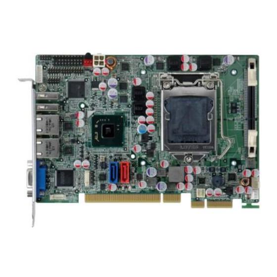
Page 14: Introduction
Figure 1-1: PICOe-B650 Half-size CPU Card The PICOe-B650 half-size PCIe CPU card is an embedded LGA1155 Intel® Core™ processor i3, i5 or i7 platform. The PICOe-B650 supports one 204-pin 1066/1333 MHz 8.0 GB (max.) DDR3 SDRAM SO-DIMM. The board includes one VGA connector, and supports a dual-display configuration. -
Page 15: Connectors
PICOe-B650 Half-size PCIe CPU Card 1.2 Connectors The connectors on the PICOe-B650 are shown in the figure below. Figure 1-2: Connectors Page 3... -
Page 16: Dimensions
PICOe-B650 Half-size PCIe CPU Card 1.3 Dimensions The dimensions of the board are listed below: Length: 185 mm Width: 122 mm Figure 1-3: PICOe-B650 Dimensions (mm) Page 4... -
Page 17: Data Flow
PICOe-B650 Half-size PCIe CPU Card 1.4 Data Flow F igure 1-4 shows the data flow between the two on-board chipsets and other components installed on the motherboard and described in the following sections of this chapter. Figure 1-4: Data Flow Block Diagram... -
Page 18: Technical Specifications
PICOe-B650 Half-size PCIe CPU Card 1.5 Technical Specifications PICOe-B650 technical specifications are listed in table below. Specification PICOe-B650 Half-size PCIe CPU Card Form Factor LGA1155 socket CPU Socket Intel® Core™ i7/i5/i3 quad-core/dual-core processor CPU Options Intel® Pentium®/Celeron® processor System Chipset Intel®... -
Page 19: Table 1-1: Technical Specifications
PICOe-B650 Half-size PCIe CPU Card Specification PICOe-B650 Two RJ-45 GbE ports Ethernet Audio Supports 7.1 channel HD audio via optional IEI AC-KIT-888HD kit Keyboard/Mouse One keyboard and mouse connector via internal 6-pin header Serial Ports Two RS-232 serial ports via internal pin header USB 2.0 ports... -
Page 20: Unpacking
PICOe-B650 Half-size PCIe CPU Card Chapter Unpacking Page 8... -
Page 21: Anti-Static Precautions
Only handle the edges of the PCB: Don't touch the surface of the motherboard. Hold the motherboard by the edges when handling. 2.2 Unpacking Precautions When the PICOe-B650 is unpacked, please do the following: Follow the antistatic guidelines above. Make sure the packing box is facing upwards when opening. -
Page 22: Unpacking Checklist
If any of the components listed in the checklist below are missing, do not proceed with the installation. Contact the IEI reseller or vendor the PICOe-B650 was purchased from or contact an IEI sales representative directly by sending an email to ales@iei.com.tw. -
Page 23: Optional Items
PICOe-B650 Half-size PCIe CPU Card One Key Recovery CD Quick Installation Guide 2.3.2 Optional Items The PICOe-B650 is shipped with the following components: Item and Part Number Image SATA power cable (P/N: 32102-000100-200-RS) KB/MS cable (with bracket) (P/N: 19800-000075-RS) 7.1 Channel HD Audio kit with Realtek ALC888 (P/N: AC-KIT-888HD-R10) SATA to IDE/CompactFlash®... - Page 24 PICOe-B650 Half-size PCIe CPU Card LGA1155/LGA1156 Cooler kit (95W) (P/N: CF-1156B-RS) LGA1155/LGA1156 Cooler kit (45W) (P/N: CF-1156C-RS) Page 12...
-
Page 25: Connectors
PICOe-B650 Half-size PCIe CPU Card Chapter Connectors Page 13... -
Page 26: Peripheral Interface Connectors
F igure 3-1 shows the on-board peripheral connectors, rear panel peripheral connectors and on-board jumpers. Figure 3-1: Connector and Jumper Locations 3.1.2 Peripheral Interface Connectors T able 3-1 shows a list of the peripheral interface connectors on the PICOe-B650. Detailed descriptions of these connectors can be found below. Connector Type... -
Page 27: External Interface Panel Connectors
8-pin header USB2 Table 3-1: Peripheral Interface Connectors 3.1.3 External Interface Panel Connectors T able 3-2 lists the rear panel connectors on the PICOe-B650. Detailed descriptions of these connectors can be found in Section 3 .3 on page 3 1. -
Page 28: Internal Peripheral Connectors
The ATX power supply enable connector enables the PICOe-B650 to be connected to an ATX power supply. In default mode, the PICOe-B650 can only use an AT power supply. To enable an ATX power supply the AT Power Select jumper must also be configured. -
Page 29: Audio Connector
PICOe-B650 Half-size PCIe CPU Card 3.2.2 Audio Connector CN Label: J_AUDIO1 9-pin header (2x5) CN Type: CN Location: See Figure 3-3 CN Pinouts: See Table 3-4 The 9-pin audio connector is connected to external audio devices including speakers and microphones for the input and output of audio signals to and from the system. -
Page 30: Battery Connector
PICOe-B650 Half-size PCIe CPU Card 3.2.3 Battery Connector CAUTION: Risk of explosion if battery is replaced by and incorrect type. Only certified engineers should replace the on-board battery. Dispose of used batteries according to instructions and local regulations. CN Label:... -
Page 31: Cpu Fan Connector
PICOe-B650 Half-size PCIe CPU Card 3.2.4 CPU Fan Connector CN Label: CPU_FAN1 4-pin wafer (1x4) CN Type: CN Location: F igure 3-5 CN Pinouts: T able 3-6 The cooling fan connector provides a 12V, 500mA current to the cooling fan. The connector has a "rotation"... -
Page 32: Digital Input/Output (Dio) Connector
PICOe-B650 Half-size PCIe CPU Card This connector accepts 12 V of power for the processor. Figure 3-6: CPU Power Connector Location Description Description +12 V +12 V Table 3-7: CPU Power Connector Pinouts 3.2.6 Digital Input/Output (DIO) Connector CN Label:... -
Page 33: Front Panel Connector
PICOe-B650 Half-size PCIe CPU Card Figure 3-7: DIO Connector Location Description Description Output 3 Output 2 Output 1 Output 0 Input 3 Input 2 Input 1 Input 0 Table 3-8: DIO Connector Connector Pinouts 3.2.7 Front Panel Connector CN Label:... -
Page 34: I2C Connector
PICOe-B650 Half-size PCIe CPU Card Figure 3-8: Front Panel Connector Location FUNCTION DESCRIPTION FUNCTION DESCRIPTION Power LED PWR_LED+ Power Button PWR_BTN PWR_LED+ HDD LED HDD_LED+ Reset RESET HDD_LED- Table 3-9: Front Panel Connector Pinouts 3.2.8 I2C Connector CN Label: I2C_1... -
Page 35: Keyboard/Mouse Connector
PICOe-B650 Half-size PCIe CPU Card Figure 3-9: I2C Connector Location Description +5V_DUAL PCH_GP38_PU PCH_GP39_PU Table 3-10: I2C Connector Pinouts 3.2.9 Keyboard/Mouse Connector CN Label: KB_MS1 6-pin header (1x6) CN Type: See Figure 3-10 CN Location: CN Pinouts: See Table 3-11 The keyboard and mouse connector can be connected to a standard PS/2 cable or PS/2 Y-cable to add keyboard and mouse functionality to the system. -
Page 36: Sata 6Gb/S Connector
PICOe-B650 Half-size PCIe CPU Card Figure 3-10: Keyboard/Mouse Connector Location Description VCC5_KBMS MS DATA MS CLK KB DATA KB CLK GROUND Table 3-11: Keyboard/Mouse Connector Pinouts 3.2.10 SATA 6Gb/s Connector CN Label: SATA1 7-pin SATA drive connector CN Type: CN Location:... -
Page 37: Sata 3Gb/S Connector
PICOe-B650 Half-size PCIe CPU Card Figure 3-11: SATA Drive Connector Location Description Table 3-12: SATA Drive Connector Pinouts 3.2.11 SATA 3Gb/s Connector CN Label: SATA2 CN Type: 7-pin SATA drive connector CN Location: F igure 3-12 CN Pinouts: T able 3-13 The SATA connectors connect to SATA hard drives or optical drives with data transfer speeds as high as 3Gb/s. -
Page 38: Serial Port Connectors (Com 1 And Com 2)
PICOe-B650 Half-size PCIe CPU Card Figure 3-12: SATA Drive Connector Location Description Table 3-13: SATA Drive Connector Pinouts 3.2.12 Serial Port Connectors (COM 1 and COM 2) CN Label: COM1, COM2 CN Type: 10-pin header (2x5) CN Location: F igure 3-13... -
Page 39: Smbus Connector
PICOe-B650 Half-size PCIe CPU Card Figure 3-13: COM Connector Locations Description Description -NDCD1 -NCTS1 -NDSR1 -NDTR1 NSIN1 -XRI1 -NRTS1 NSOUT1 Table 3-14: COM Connector Pinouts 3.2.13 SMBus Connector CN Label: SMBUS_1 CN Type: 4-pin wafer (1x4) See Figure 3-14 CN Location:... -
Page 40: Spi Flash Connector
PICOe-B650 Half-size PCIe CPU Card Figure 3-14: SMBus Connector Location Description +5V_DUAL SMBCLK SMBDATA Table 3-15: SMBus Connector Pinouts 3.2.14 SPI Flash Connector CN Label: JSPI1 6-pin header (1x6) CN Type: CN Location: See Figure 3-15 CN Pinouts: See Table 3-16 The SPI Flash connector is used to flash the BIOS. -
Page 41: Tpm Connector
PICOe-B650 Half-size PCIe CPU Card Description SPI_VCC SPI_CS# SPI_MISO SPI_CLK SPI_MOSI Table 3-16: SPI Flash Connector 3.2.15 TPM Connector CN Label: TPM1 CN Type: 20-pin header (2x10) CN Location: See Figure 3-16 CN Pinouts: See Table 3-17 The Trusted Platform Module (TPM) connector secures the system on bootup. -
Page 42: Usb Connectors (Internal)
PICOe-B650 Half-size PCIe CPU Card Description Description LAD3 LAD2 LAD1 LAD0 GND3 SB3V SERIRQ GND1 GLKRUN# LPCPD# LDRQ# Table 3-17: TPM Connector Pinouts 3.2.16 USB Connectors (Internal) CN Label: USB2 8-pin header (2x4) CN Type: CN Location: F igure 3-17... -
Page 43: External Peripheral Interface Connector Panel
DATA- Table 3-18: USB Port Connector Pinouts 3.3 External Peripheral Interface Connector Panel F igure 3-18 shows the PICOe-B650 external peripheral interface connector (EPIC) panel. The PICOe-B650 EPIC panel consists of the following: 2 x RJ-45 LAN connectors 2 x USB connectors... -
Page 44: Usb Connectors
3.3.2 USB Connectors CN Label: USB_C1, USB_C2 CN Type: USB port F igure 3-18 CN Location: CN Pinouts: T able 3-21 The PICOe-B650 has two external USB 2.0 ports. The ports connect to both USB 2.0 and USB 1.1 devices. Page 32... -
Page 45: Vga Connector
15-pin Female CN Type: CN Location: F igure 3-18 CN Pinouts: F igure 3-20 and T able 3-22 The PICOe-B650 has a single 15-pin female connector for connectivity to standard display devices. Figure 3-20: VGA Connector Description Description GREEN BLUE... -
Page 46: Installation
PICOe-B650 Half-size PCIe CPU Card Chapter Installation Page 34... -
Page 47: Anti-Static Precautions
Electrostatic discharge (ESD) can cause serious damage to electronic components, including the PICOe-B650. Dry climates are especially susceptible to ESD. It is therefore critical that whenever the PICOe-B650 or any other electrical component is handled, the following anti-static precautions are strictly adhered to. -
Page 48: Installation Considerations
PICOe-B650 is installed. All installation notices pertaining to the installation of the PICOe-B650 should be strictly adhered to. Failing to adhere to these precautions may lead to severe damage of the PICOe-B650 and injury to the person installing the CPU card. WARNING:... -
Page 49: Cpu And Memory Installation
CPUs marked as fanless don't need the fan, but still need adequate ventilation. The CPU, CPU cooling kit and DIMM are the most critical components of the PICOe-B650. If one of these component is not installed the PICOe-B650 cannot run. -
Page 50: Figure 4-1: Disengage The Cpu Socket Load Lever
PICOe-B650 Half-size PCIe CPU Card Step 1: Disengage the load lever by pressing the lever down and slightly outward to clear the retention tab. Fully open the lever. See Figure 4-1. Figure 4-1: Disengage the CPU Socket Load Lever Step 2: Open the socket and remove the protective cover. -
Page 51: Figure 4-3: Insert The Socket Lga1155 Cpu
PICOe-B650 Half-size PCIe CPU Card Step 3: Inspect the CPU socket. Make sure there are no bent pins and make sure the socket contacts are free of foreign material. If any debris is found, remove it with compressed air. Step 4: Orientate the CPU properly. -
Page 52: Socket Lga1155 Cooling Kit Installation
PICOe-B650 Half-size PCIe CPU Card pushing it back to its original position (Figure 4-4). There will be some resistance, but will not require extreme pressure. Figure 4-4: Close the Socket LGA1155 Step 9: Connect the 12 V power to the board. Connect the 12 V power from the power supply to the board. -
Page 53: Figure 4-5: Cooling Kit Support Bracket
PICOe-B650 Half-size PCIe CPU Card WARNING: Do not wipe off (accidentally or otherwise) the pre-sprayed layer of thermal paste on the bottom of the heat sink. The thermal paste between the CPU and the heat sink is important for optimum heat dissipation. -
Page 54: So-Dimm Installation
PICOe-B650 Half-size PCIe CPU Card Step 5: Connect the fan cable. Connect the cooling kit fan cable to the fan connector on the PICOe-B650. Carefully route the cable and avoid heat generating chips and fan blades. Step 0: 4.3.3 SO-DIMM Installation To install a SO-DIMM, please follow the steps below and refer to Figure 4-6. -
Page 55: Jumper Settings
OPEN a jumper means removing the plastic clip from a jumper. Before the PICOe-B650 is installed in the system, the jumpers must be set in accordance with the desired configuration. The jumpers on the PICOe-B650 are listed in T able 4-1. -
Page 56: Clear Cmos Jumper
Jumper Location: F igure 4-8 If the PICOe-B650 fails to boot due to improper BIOS settings, the clear CMOS jumper clears the CMOS data and resets the system BIOS information. To do this, use the jumper cap to close pins 2 and 3 for a few seconds then reinstall the jumper clip back to pins 1 and 2. -
Page 57: Pcie Status Select Jumper
PICOe-B650 Half-size PCIe CPU Card The clear CMOS jumper settings are shown in T able 4-3. Setting Description Short 1 - 2 Keep CMOS Setup (Default) Short 2 - 3 Clear CMOS Setup Table 4-3: Clear CMOS Jumper Settings The location of the clear CMOS jumper is shown in F igure 4-8 below. -
Page 58: Chassis Installation
The PICOe-B650 must be installed in a chassis with ventilation holes on the sides allowing airflow to travel through the heat sink surface. In a system with an individual power supply unit, the cooling fan of a power supply can also help generate airflow through the board surface. -
Page 59: Cpu Card Installation
4.5.3 CPU Card Installation To install the PICOe-B650 CPU card onto the backplane, carefully align the CPU card interface connectors with the corresponding socket on the backplane. To do this, please refer to the reference material that came with the backplane. Next, secure the CPU card to the chassis. -
Page 60: Sata Drive Connection
0: 4.6.2 SATA Drive Connection The PICOe-B650 is shipped with two SATA drive cables. To connect the SATA drives to the connectors, please follow the steps below. Step 1: Locate the connectors. The locations of the SATA drive connectors are shown in Chapter 3. -
Page 61: Figure 4-11: Sata Drive Cable Connection
PICOe-B650 Half-size PCIe CPU Card Figure 4-11: SATA Drive Cable Connection Step 3: Connect the cable to the SATA disk. Connect the connector on the other end of the cable to the connector at the back of the SATA drive. See F igure 4-12. -
Page 62: Usb Cable (Dual Port) With Slot Bracket
PICOe-B650 Half-size PCIe CPU Card Figure 4-12: SATA Power Drive Connection 4.6.3 USB Cable (Dual Port) with Slot Bracket The PICOe-B650 is shipped with a dual port USB 2.0 cable. To connect the USB cable connector, please follow the steps below. Step 1: Locate the connectors. -
Page 63: External Peripheral Interface Connection
RJ-45 Ethernet cable connectors USB devices VGA monitors To install these devices, connect the corresponding cable connector from the actual device to the corresponding PICOe-B650 external peripheral interface connector making sure the pins are properly aligned. Page 51... -
Page 64: Lan Connection
Locate the RJ-45 connectors. The locations of the USB connectors are shown in Chapter 3. Step 2: Align the connectors. Align the RJ-45 connector on the LAN cable with one of the RJ-45 connectors on the PICOe-B650. See F igure 4-14. Figure 4-14: LAN Connection Step 3: Insert the LAN cable RJ-45 connector. -
Page 65: Vga Monitor Connection
Figure 4-15: USB Connector 4.7.3 VGA Monitor Connection The PICOe-B650 has a single female DB-15 connector on the external peripheral interface panel. The DB-15 connector is connected to a CRT or VGA monitor. To connect a monitor to the PICOe-B650, please follow the instructions below. -
Page 66: Software Installation
Step 0: 4.8 Software Installation All the drivers for the PICOe-B650 are on the CD that came with the system. To install the drivers, please follow the steps below. Step 1: Insert the CD into a CD drive connected to the system. -
Page 67: Figure 4-17: Introduction Screen
PICOe-B650 Half-size PCIe CPU Card Figure 4-17: Introduction Screen Step 3: Click PICOe-B650. Step 4: A new screen with a list of available drivers appears (Figure 4-18). Figure 4-18: Available Drivers Step 5: Install all of the necessary drivers in this menu. -
Page 68: Bios Screens
PICOe-B650 Half-size PCIe CPU Card Chapter BIOS Screens Page 56... -
Page 69: Introduction
PICOe-B650 Half-size PCIe CPU Card 5.1 Introduction The BIOS is programmed onto the BIOS chip. The BIOS setup program allows changes to certain system settings. This chapter outlines the options that can be changed. 5.1.1 Starting Setup The AMI BIOS is activated when the computer is turned on. The setup program can be activated in one of two ways. -
Page 70: Getting Help
PICOe-B650 Half-size PCIe CPU Card Function F4 key Save all the CMOS changes Esc key Main Menu – Quit and not save changes into CMOS Status Page Setup Menu and Option Page Setup Menu -- Exit current page and return to Main Menu Table 5-1: BIOS Navigation Keys 5.1.3 Getting Help... -
Page 71: Main
PICOe-B650 Half-size PCIe CPU Card 5.2 Main The Main BIOS menu (BIOS Menu 1) appears when the BIOS Setup program is entered. The Main menu gives an overview of the basic system information. Aptio Setup Utility – Copyright (C) 2011 American Megatrends, Inc. -
Page 72: Advanced
PICOe-B650 Half-size PCIe CPU Card System Date [xx/xx/xx] Use the System Date option to set the system date. Manually enter the day, month and year. System Time [xx:xx:xx] Use the System Time option to set the system time. Manually enter the hours, minutes and seconds. -
Page 73: Acpi Settings
PICOe-B650 Half-size PCIe CPU Card 5.3.1 ACPI Settings The ACPI Settings menu (BIOS Menu 3) configures the Advanced Configuration and Power Interface (ACPI) options. Aptio Setup Utility – Copyright (C) 2010 American Megatrends, Inc. Advanced ACPI Settings Select the highest ACPI... -
Page 74: Trusted Computing
PICOe-B650 Half-size PCIe CPU Card 5.3.2 Trusted Computing Use the Trusted Computing menu (BIOS Menu 4) to configure settings related to the Trusted Computing Group (TCG) Trusted Platform Module (TPM). Aptio Setup Utility – Copyright (C) 2011 American Megatrends, Inc. -
Page 75: Cpu Information
PICOe-B650 Half-size PCIe CPU Card Aptio Setup Utility – Copyright (C) 2011 American Megatrends, Inc. Advanced CPU Configuration Socket specific CPU Information > CPU Information Intel Virtualization Technology [Disabled] ---------------------- : Select Screen ↑ ↓: Select Item Enter Select Change Opt. -
Page 76: Bios Menu 6: Cpu Configuration
PICOe-B650 Half-size PCIe CPU Card Aptio Setup Utility – Copyright (C) 2011 American Megatrends, Inc. Advanced CPU Configuration Intel(R) Pentium(R) CPU G850 @ 2.90GHz CPU Signature 206a7 ---------------------- Microcode Patch Max CPU Speed 2900 MHz : Select Screen ↑ ↓: Select Item... -
Page 77: Sata Configuration
PICOe-B650 Half-size PCIe CPU Card 5.3.4 SATA Configuration Use the SATA Configuration menu (BIOS Menu 7) to change and/or set the configuration of the SATA devices installed in the system. Aptio Setup Utility – Copyright (C) 2011 American Megatrends, Inc. -
Page 78: Intel Txt(Lt) Configuration
PICOe-B650 Half-size PCIe CPU Card Disable Disables SATA devices. Configures SATA devices as normal IDE device. IDE Mode EFAULT AHCI Mode Configures SATA devices as AHCI device. Serial-ATA Controller n Use the Serial-ATA Controller option to configure the SATA controller. -
Page 79: Usb Configuration
PICOe-B650 Half-size PCIe CPU Card 5.3.6 USB Configuration Use the USB Configuration menu (BIOS Menu 9) to read USB configuration information and configure the USB settings. Aptio Setup Utility – Copyright (C) 2011 American Megatrends, Inc. Advanced USB Configuration USB Support Parameters... -
Page 80: Super Io Configuration
PICOe-B650 Half-size PCIe CPU Card keyboard can control the system even when there is no USB driver loaded onto the system. Enabled Legacy USB support enabled EFAULT Disabled Legacy USB support disabled 5.3.7 Super IO Configuration Use the Super IO Configuration menu (BIOS Menu 10) to set or change the configurations for the FDD controllers, parallel ports and serial ports. -
Page 81: Serial Port N Configuration
PICOe-B650 Half-size PCIe CPU Card 5.3.7.1 Serial Port n Configuration Use the Serial Port n Configuration menu (BIOS Menu 11) to configure the serial port n. Aptio Setup Utility – Copyright (C) 2011 American Megatrends, Inc. Advanced Serial Port n Configuration... - Page 82 PICOe-B650 Half-size PCIe CPU Card IO=3F8h; Serial Port I/O port address is 3F8h and the interrupt IRQ=3, 4 address is IRQ3, 4 Serial Port I/O port address is 2F8h and the interrupt IO=2F8h; address is IRQ3, 4 IRQ=3, 4 IO=2C0h;...
-
Page 83: H/W Monitor
PICOe-B650 Half-size PCIe CPU Card IO=2C8h; Serial Port I/O port address is 2C8h and the interrupt IRQ=3, 4 address is IRQ3, 4 5.3.8 H/W Monitor The H/W Monitor menu (BIOS Menu 12) contains the fan configuration submenus and displays operating temperature, fan speeds and system voltages. -
Page 84: Fan 1 Configuration
PICOe-B650 Half-size PCIe CPU Card VCC3V Vcore +1.05V VDDR VSB3V VBAT 5VSB 5.3.8.1 FAN 1 Configuration Use the FAN 1 Configuration submenu (BIOS Menu 13) to configure fan 1 temperature and speed settings. Aptio Setup Utility – Copyright (C) 2011 American Megatrends, Inc. - Page 85 PICOe-B650 Half-size PCIe CPU Card Auto The fan adjusts its speed using Auto by Duty-Cycle Duty-Cycle settings The fan spins at the speed set in Manual by RPM Manual settings Manual The fan spins at the speed set in Manual by Duty...
-
Page 86: Serial Port Console Redirection
PICOe-B650 Half-size PCIe CPU Card 5.3.9 Serial Port Console Redirection The Serial Port Console Redirection menu (BIOS Menu 14) allows the console redirection options to be configured. Console redirection allows users to maintain a system remotely by re-directing keyboard input and text output through the serial port. -
Page 87: Iei Feature
PICOe-B650 Half-size PCIe CPU Card 5.3.10 IEI Feature Use the IEI Feature menu (BIOS Menu 23) to configure One Key Recovery function. BIOS SETUP UTILITY Advanced Auto Recovery Function iEi Feature Reboot and recover ⎯⎯⎯⎯⎯⎯⎯⎯⎯⎯⎯⎯⎯⎯⎯⎯⎯⎯⎯⎯⎯⎯⎯⎯⎯⎯⎯⎯⎯⎯⎯ system automatically within 10 min, when OS... -
Page 88: Bios Menu 16: Chipset
PICOe-B650 Half-size PCIe CPU Card WARNING! Setting the wrong values for the Chipset BIOS selections in the Chipset BIOS menu may cause the system to malfunction. Aptio Setup Utility – Copyright (C) 2011 American Megatrends, Inc. Main Advanced Chipset Boot Security Save &... -
Page 89: Northbridge Configuration
PICOe-B650 Half-size PCIe CPU Card 5.4.1 Northbridge Configuration Use the Northbridge Chipset Configuration menu (BIOS Menu 17) to configure the Northbridge chipset. Aptio Setup Utility – Copyright (C) 2011 American Megatrends, Inc. Chipset Memory Information Select which graphics controller to use as the... - Page 90 PICOe-B650 Half-size PCIe CPU Card IGD Memory [64M] Use the IGD Memory option to specify the amount of system memory that can be used by the Internal graphics device. Disable 32 MB of memory used by internal graphics device 32 M...
-
Page 91: Southbridge Configuration
PICOe-B650 Half-size PCIe CPU Card 480 M 480 MB of memory used by internal graphics device 512 MB of memory used by internal graphics 512 M device VT-d [Disabled] Use the VT-d option to enable or disable VT-d support. Disabled Disables VT-d support. -
Page 92: Integrated Graphics
PICOe-B650 Half-size PCIe CPU Card Power Off The system remains turned off EFAULT The system turns on Power On Azalia HD Audio [Enabled] Use the Azalia HD Audio option to enable or disable the High Definition Audio controller. Disabled The onboard High Definition Audio controller is disabled... -
Page 93: Boot
PICOe-B650 Half-size PCIe CPU Card DVMT Mode Select [DVMT Mode] Use the DVMT Mode Select option to select the Intel Dynamic Video Memory Technology (DVMT) operating mode. Fixed Mode A fixed portion of graphics memory is reserved as graphics memory. - Page 94 PICOe-B650 Half-size PCIe CPU Card Bootup NumLock State [On] Use the Bootup NumLock State BIOS option to specify if the number lock setting must be modified during boot up. Allows the Number Lock on the keyboard to be EFAULT enabled automatically when the computer system boots up.
-
Page 95: Security
PICOe-B650 Half-size PCIe CPU Card Force Sets display mode to force BIOS. BIOS Sets display mode to current. Keep EFAULT Current 5.6 Security Use the Security menu (BIOS Menu 21) to set system and user passwords. Aptio Setup Utility – Copyright (C) 2011 American Megatrends, Inc. -
Page 96: Exit
PICOe-B650 Half-size PCIe CPU Card 5.7 Exit Use the Exit menu (BIOS Menu 22) to load default BIOS values, optimal failsafe values and to save configuration changes. Aptio Setup Utility – Copyright (C) 2011 American Megatrends, Inc. Main Advanced Chipset... - Page 97 PICOe-B650 Half-size PCIe CPU Card Save as User Defaults Use the Save as User Defaults option to save the changes done so far as user defaults. Restore User Defaults Use the Restore User Defaults option to restore the user defaults to all the setup options.
-
Page 98: Abios Options
PICOe-B650 Half-size PCIe CPU Card Appendix BIOS Options Page 86... - Page 99 PICOe-B650 Half-size PCIe CPU Card Below is a list of BIOS configuration options in the BIOS chapter. System Overview .........................59 Memory Information ......................59 System Date [xx/xx/xx] ......................60 System Time [xx:xx:xx] .......................60 ACPI Sleep State [S1 (CPU Stop Clock)] ................61 ...
- Page 100 PICOe-B650 Half-size PCIe CPU Card Quiet Boot [Enabled] ......................82 Launch PXE OpROM [Disabled] ..................82 Option ROM Messages [Keep Current] ................82 Administrator Password .....................83 User Password ........................83 Save Changes and Reset ....................84 Discard Changes and Reset ....................84 ...
-
Page 101: B One Key Recovery
PICOe-B650 Half-size PCIe CPU Card Appendix One Key Recovery Page 89... -
Page 102: One Key Recovery Introduction
PICOe-B650 Half-size PCIe CPU Card B.1 One Key Recovery Introduction The IEI one key recovery is an easy-to-use front end for the Norton Ghost system backup and recovery tool. This tool provides quick and easy shortcuts for creating a backup and reverting to that backup or reverting to the factory default settings. -
Page 103: System Requirement
PICOe-B650 Half-size PCIe CPU Card After completing the five initial setup procedures as described above, users can access the recovery tool by pressing <F3> while booting up the system. The detailed information of each function is described in Section B.5. -
Page 104: Supported Operating System
PICOe-B650 Half-size PCIe CPU Card partitions. Please take the following table as a reference when calculating the size of the partition. OS Image after Ghost Compression Ratio Windows® 7 7 GB 5 GB Windows® XPE 776 MB 560 MB Windows® CE 6.0... -
Page 105: Setup Procedure For Windows
PICOe-B650 Half-size PCIe CPU Card Linux Fedora Core 12 (Constantine) Fedora Core 11 (Leonidas) Fedora Core 10 (Cambridge) Fedora Core 8 (Werewolf) Fedora Core 7 (Moonshine) RedHat RHEL-5.4 RedHat 9 (Ghirke) Ubuntu 8.10 (Intrepid) Ubuntu 7.10 (Gutsy) Ubuntu 6.10 (Edgy) Debian 5.0 (Lenny) -
Page 106: Hardware And Bios Setup
PICOe-B650 Half-size PCIe CPU Card The detailed descriptions are described in the following sections. NOTE: The setup procedures described below are for Microsoft Windows operating system users. For Linux, most of the setup procedures are the same except for several steps described in Section B.3. -
Page 107: Figure B-2: Launching The Recovery Tool
PICOe-B650 Half-size PCIe CPU Card Step 2: Boot the system from recovery CD. When prompted, press any key to boot from the recovery CD. It will take a while to launch the recovery tool. Please be patient! Figure B-2: Launching the Recovery Tool Step 3: The recovery tool setup menu is shown as below. -
Page 108: Figure B-4: Command Prompt
PICOe-B650 Half-size PCIe CPU Card Figure B-4: Command Prompt Step 5: The command prompt window appears. Type the following commands (marked in red) to create two partitions. One is for the OS installation; the other is for saving recovery files and images which will be an invisible partition. -
Page 109: Figure B-5: Partition Creation Commands
PICOe-B650 Half-size PCIe CPU Card Figure B-5: Partition Creation Commands Page 97... -
Page 110: Install Operating System, Drivers And Applications
PICOe-B650 Half-size PCIe CPU Card NOTE: Use the following commands to check if the partitions were created successfully. Step 6: Press any key to exit the recovery tool and automatically reboot the system. Please continue to the following procedure: Build the Recovery Partition.S t e p 0 :... -
Page 111: Building The Recovery Partition
PICOe-B650 Half-size PCIe CPU Card B.2.4 Building the Recovery Partition Step 1: Put the recover CD in the optical drive. Step 2: Start the system. Step 3: Boot the system from the recovery CD. When prompted, press any key to boot from the recovery CD. -
Page 112: Figure B-8: Building The Recovery Partition
PICOe-B650 Half-size PCIe CPU Card Step 5: The Symantec Ghost window appears and starts configuring the system to build a recovery partition. In this process the partition created for recovery files in Section B.2.2 is hidden and the recovery tool is saved in this partition. -
Page 113: Create Factory Default Image
PICOe-B650 Half-size PCIe CPU Card B.2.5 Create Factory Default Image NOTE: Before creating the factory default image, please configure the system to a factory default environment, including driver and application installations. To create a factory default image, please follow the steps below. -
Page 114: Figure B-12: About Symantec Ghost Window
PICOe-B650 Half-size PCIe CPU Card Figure B-12: About Symantec Ghost Window Step 4: Use mouse to navigate to the option shown below (Figure B-13). Figure B-13: Symantec Ghost Path Step 5: Select the local source drive (Drive 1) as shown in Figure B-14. Then click OK. -
Page 115: Figure B-14: Select A Local Source Drive
PICOe-B650 Half-size PCIe CPU Card Figure B-14: Select a Local Source Drive Step 6: Select a source partition (Part 1) from basic drive as shown in Figure B-15. Then click OK. Figure B-15: Select a Source Partition from Basic Drive Step 7: Select 1.2: [Recovery] NTFS drive and enter a file name called... -
Page 116: Figure B-16: File Name To Copy Image To
PICOe-B650 Half-size PCIe CPU Card Figure B-16: File Name to Copy Image to Step 8: When the Compress Image screen in Figure B-17 prompts, click High to make the image file smaller. Figure B-17: Compress Image Page 104... -
Page 117: Figure B-18: Image Creation Confirmation
PICOe-B650 Half-size PCIe CPU Card Step 9: The Proceed with partition image creation window appears, click Yes to continue. Figure B-18: Image Creation Confirmation Step 10: The Symantec Ghost starts to create the factory default image (Figure B-19). Figure B-19: Image Creation Complete Step 11: When the image creation completes, a screen prompts as shown in Figure B-20. -
Page 118: Auto Recovery Setup Procedure
PICOe-B650 Half-size PCIe CPU Card Step 12: The recovery tool main menu window is shown as below. Press any key to reboot the system. S t e p 0 : Figure B-21: Press Any Key to Continue B.3 Auto Recovery Setup Procedure... -
Page 119: Figure B-22: Auto Recovery Utility
PICOe-B650 Half-size PCIe CPU Card Step 1: Follow the steps described in Section B.2.1 ~ Section B.2.3 to setup BIOS, create partitions and install operating system. Step 2: Install the auto recovery utility into the system by double clicking the Utility/AUTORECOVERY-SETUP.exe in the One Key Recovery CD. -
Page 120: Figure B-24: Launching The Recovery Tool
PICOe-B650 Half-size PCIe CPU Card Step 4: Reboot the system from the recovery CD. When prompted, press any key to boot from the recovery CD. It will take a while to launch the recovery tool. Please be patient! Figure B-24: Launching the Recovery Tool Step 5: When the recovery tool setup menu appears, press <4>... -
Page 121: Figure B-26: Building The Auto Recovery Partition
PICOe-B650 Half-size PCIe CPU Card Figure B-26: Building the Auto Recovery Partition Step 7: After completing the system configuration, the following message prompts to confirm whether to create a factory default image. Type Y to have the system create a factory default image automatically. Type N within 6 seconds to skip this process (The default option is YES). -
Page 122: Figure B-28: Image Creation Complete
PICOe-B650 Half-size PCIe CPU Card Step 8: The Symantec Ghost starts to create the factory default image (Figure B-28). Figure B-28: Image Creation Complete Step 9: After completing the system configuration, press any key in the following window to restart the system. -
Page 123: Setup Procedure For Linux
PICOe-B650 Half-size PCIe CPU Card BIOS SETUP UTILITY Main Advanced PCIPNP Boot Security Chipset Exit iEi Feature ⎯⎯⎯⎯⎯⎯⎯⎯⎯⎯⎯⎯⎯⎯⎯⎯⎯⎯⎯⎯⎯⎯⎯⎯⎯⎯⎯ Auto Recovery Function [Enabled] Recover from PXE [Disabled] Select Screen ↑ ↓ Select Item Enter Go to SubScreen General Help Save and Exit Exit v02.61 ©Copyright 1985-2006, American Megatrends, Inc. -
Page 124: Figure B-30: Partitions For Linux
PICOe-B650 Half-size PCIe CPU Card Partition 1: / Partition 2: SWAP NOTE: Please reserve enough space for partition 3 for saving recovery images. Figure B-30: Partitions for Linux Step 3: Create a recovery partition. Insert the recovery CD into the optical disk drive. -
Page 125: Figure B-31: Manual Recovery Environment For Linux
PICOe-B650 Half-size PCIe CPU Card recovery partition. After completing the system configuration, press any key to reboot the system. Eject the recovery CD. Figure B-31: Manual Recovery Environment for Linux Step 5: Access the recovery tool main menu by modifying the “menu.lst”. To first access the recovery tool main menu, the menu.lst must be modified. -
Page 126: Recovery Tool Functions
PICOe-B650 Half-size PCIe CPU Card Step 7: The recovery tool menu appears. (Figure B-33) Figure B-33: Recovery Tool Menu Step 8: Create a factory default image. Follow Step 2 Step 12 described in Section B.2.5 to create a factory default image. -
Page 127: Figure B-34: Recovery Tool Main Menu
PICOe-B650 Half-size PCIe CPU Card Figure B-34: Recovery Tool Main Menu The recovery tool has several functions including: 1. Factory Restore: Restore the factory default image (iei.GHO) created in Section B.2.5. 2. Backup system: Create a system backup image (iei_user.GHO) which will be saved in the hidden partition. -
Page 128: Factory Restore
PICOe-B650 Half-size PCIe CPU Card B.5.1 Factory Restore To restore the factory default image, please follow the steps below. Step 1: Type <1> and press <Enter> in the main menu. Step 2: The Symantec Ghost window appears and starts to restore the factory default. A factory default image called iei.GHO is created in the hidden Recovery partition. -
Page 129: Backup System
PICOe-B650 Half-size PCIe CPU Card B.5.2 Backup System To backup the system, please follow the steps below. Step 1: Type <2> and press <Enter> in the main menu. Step 2: The Symantec Ghost window appears and starts to backup the system. A backup image called iei_user.GHO is created in the hidden Recovery partition. -
Page 130: Restore Your Last Backup
PICOe-B650 Half-size PCIe CPU Card B.5.3 Restore Your Last Backup To restore the last system backup, please follow the steps below. Step 1: Type <3> and press <Enter> in the main menu. Step 2: The Symantec Ghost window appears and starts to restore the last backup image (iei_user.GHO). -
Page 131: Manual
PICOe-B650 Half-size PCIe CPU Card B.5.4 Manual To restore the last system backup, please follow the steps below. Step 1: Type <4> and press <Enter> in the main menu. Step 2: The Symantec Ghost window appears. Use the Ghost program to backup or recover the system manually. -
Page 132: Restore Systems From A Linux Server Through Lan
PICOe-B650 Half-size PCIe CPU Card B.6 Restore Systems from a Linux Server through LAN The One Key Recovery allows a client system to automatically restore to a factory default image saved in a Linux system (the server) through LAN connectivity after encountering a Blue Screen of Death (BSoD) or a hang for around 10 minutes. -
Page 133: Configure Dhcp Server Settings
PICOe-B650 Half-size PCIe CPU Card B.6.1 Configure DHCP Server Settings Step 1: Install the DHCP #yum install dhcp (CentOS, commands marked in red) #apt-get install dhcp3-server (Debian, commands marked in blue) Step 2: Confirm the operating system default settings: dhcpd.conf. -
Page 134: Configure Tftp Settings
PICOe-B650 Half-size PCIe CPU Card filename “pxelinux.0”; B.6.2 Configure TFTP Settings Step 1: Install the tftp, httpd and syslinux. #yum install tftp-server httpd syslinux (CentOS) #apt-get install tftpd-hpa xinetd syslinux (Debian) Step 2: Enable the TFTP server by editing the “/etc/xinetd.d/tftp” file and make it use the remap file. -
Page 135: Configure One Key Recovery Server Settings
PICOe-B650 Half-size PCIe CPU Card Debian Replace the TFTP settings from “inetd” to “xinetd” and annotate the “inetd” by adding “#”. #vi /etc/inetd.conf Modify: #tftp dgram udp wait root /usr/sbin..(as shown below) #vi /etc/xinetd.d/tftp B.6.3 Configure One Key Recovery Server Settings Step 1: Copy the Utility/RECOVERYR10.TAR.BZ2 package from the One Key... -
Page 136: Start The Dhcp, Tftp And Http
PICOe-B650 Half-size PCIe CPU Card B.6.4 Start the DHCP, TFTP and HTTP Start the DHCP, TFTP and HTTP. For example: CentOS #service xinetd restart #service httpd restart #service dhcpd restart Debian #/etc/init.d/xinetd reload #/etc/init.d/xinetd restart #/etc/init.d/dhcp3-server restart B.6.5 Create Shared Directory Step 1: Install the samba. -
Page 137: Setup A Client System For Auto Recovery
PICOe-B650 Half-size PCIe CPU Card Modify: [image] comment = One Key Recovery path = /share/image browseable = yes writable = yes public = yes create mask = 0644 directory mask = 0755 Step 4: Edit “/etc/samba/smb.conf” for your environment. For example:... -
Page 138: Figure B-42: Disable Automatically Restart
PICOe-B650 Half-size PCIe CPU Card Figure B-42: Disable Automatically Restart Step 2: Configure the following BIOS options of the client system. Advanced → iEi Feature → Auto Recovery Function → Enabled Advanced → iEi Feature → Recover from PXE → Enabled Boot →... - Page 139 PICOe-B650 Half-size PCIe CPU Card MUST be installed in the system, otherwise, the system will automatically restore from the factory default image every ten (10) minutes. Step 6: Restart the client system from LAN. If the system encounters a Blue Screen of Death (BSoD) or a hang for around 10 minutes, it will automatically restore from the factory default image.
-
Page 140: Other Information
PICOe-B650 Half-size PCIe CPU Card NOTE: A firewall or a SELinux is not in use in the whole setup process described above. If there is a firewall or a SELinux protecting the system, modify the configuration information to accommodate them. - Page 141 PICOe-B650 Half-size PCIe CPU Card Step 5: When the following window appears, press <S> to select “Specify Additional Device”. Page 129...
-
Page 142: System Memory Requirement
PICOe-B650 Half-size PCIe CPU Card Step 6: In the following window, select a SATA controller mode used in the system. Then press <Enter>. The user can now start using the SATA HDD. Step 7: After pressing <Enter>, the system will get into the recovery tool setup menu. -
Page 143: C Terminology
PICOe-B650 Half-size PCIe CPU Card Appendix Terminology Page 131... - Page 144 PICOe-B650 Half-size PCIe CPU Card AC ’97 Audio Codec 97 (AC’97) refers to a codec standard developed by Intel® in 1997. ACPI Advanced Configuration and Power Interface (ACPI) is an OS-directed configuration, power management, and thermal management interface. AHCI Advanced Host Controller Interface (AHCI) is a SATA Host controller register-level interface.
- Page 145 PICOe-B650 Half-size PCIe CPU Card Direct Memory Access (DMA) enables some peripheral devices to bypass the system processor and communicate directly with the system memory. DIMM Dual Inline Memory Modules are a type of RAM that offer a 64-bit data bus and have separate electrical contacts on each side of the module.
- Page 146 PICOe-B650 Half-size PCIe CPU Card Liquid crystal display (LCD) is a flat, low-power display device that consists of two polarizing plates with a liquid crystal panel in between. LVDS Low-voltage differential signaling (LVDS) is a dual-wire, high-speed differential electrical signaling system commonly used to connect LCD displays to a computer.
-
Page 147: D Digital I/O Interface
PICOe-B650 Half-size PCIe CPU Card Appendix Digital I/O Interface Page 135... -
Page 148: Introduction
PICOe-B650 Half-size PCIe CPU Card D.1 Introduction The DIO connector on the PICOe-B650 is interfaced to GPIO ports on the Super I/O chipset. The DIO has both 4-bit digital inputs and 4-bit digital outputs. The digital inputs and digital outputs are generally control signals that control the on/off circuit of external devices or TTL devices. -
Page 149: Assembly Language Samples
PICOe-B650 Half-size PCIe CPU Card D.3 Assembly Language Samples D.3.1 Enable the DIO Input Function The BIOS interrupt call INT 15H controls the digital I/O. An assembly program to enable digital I/O input functions is listed below. Sets the digital port as input... -
Page 150: E Watchdog Timer
PICOe-B650 Half-size PCIe CPU Card Appendix Watchdog Timer Page 138... - Page 151 PICOe-B650 Half-size PCIe CPU Card NOTE: The following discussion applies to DOS. Contact IEI support or visit the IEI website for drivers for other operating systems. The Watchdog Timer is a hardware-based timer that attempts to restart the system when it stops working.
- Page 152 PICOe-B650 Half-size PCIe CPU Card NOTE: The Watchdog Timer is activated through software. The software application that activates the Watchdog Timer must also deactivate it when closed. If the Watchdog Timer is not deactivated, the system will automatically restart after the Timer has finished its countdown.
-
Page 153: F Hazardous Materials Disclosure
PICOe-B650 Half-size PCIe CPU Card Appendix Hazardous Materials Disclosure Page 141... -
Page 154: Hazardous Materials Disclosure Table For Ipb Products Certified As Rohs Compliant Under 2002/95/Ec Without Mercury
PICOe-B650 Half-size PCIe CPU Card F.1 Hazardous Materials Disclosure Table for IPB Products Certified as RoHS Compliant Under 2002/95/EC Without Mercury The details provided in this appendix are to ensure that the product is compliant with the Peoples Republic of China (China) RoHS standards. The table below acknowledges the presences of small quantities of certain materials in the product, and is applicable to China RoHS only. - Page 155 PICOe-B650 Half-size PCIe CPU Card Part Name Toxic or Hazardous Substances and Elements Lead Mercury Cadmium Hexavalent Polybrominated Polybrominated Biphenyls Diphenyl (Pb) (Hg) (Cd) Chromium (CR(VI)) (PBB) Ethers (PBDE) Housing Display Printed Circuit Board Metal Fasteners Cable Assembly Fan Assembly...
- Page 156 PICOe-B650 Half-size PCIe CPU Card 此附件旨在确保本产品符合中国 RoHS 标准。以下表格标示此产品中某有毒物质的含量符 合中国 RoHS 标准规定的限量要求。 本产品上会附有”环境友好使用期限”的标签,此期限是估算这些物质”不会有泄漏或突变”的 年限。本产品可能包含有较短的环境友好使用期限的可替换元件,像是电池或灯管,这些元 件将会单独标示出来。 部件名称 有毒有害物质或元素 铅 汞 镉 六价铬 多溴联苯 多溴二苯 醚 (Pb) (Hg) (Cd) (CR(VI)) (PBB) (PBDE) 壳体 显示 印刷电路板 金属螺帽 电缆组装 风扇组装 电力供应组装 电池 O: 表示该有毒有害物质在该部件所有物质材料中的含量均在 SJ/T11363-2006 标准规定的限量要求以下。...
Need help?
Do you have a question about the PICOe-B650 and is the answer not in the manual?
Questions and answers