Table of Contents
Advertisement
Quick Links
Download this manual
See also:
User Manual
Half-size PCIe CPU Card Supports Socket 989B 32nm
Intel® mobile Core™ i7/i5/i3 CPU with Intel® HM65, DDR3,
VGA/LVDS, Dual PCIe GbE, SATA 6Gb/s, HD Audio and RoHS
Quick Installation Guide
Package List
PICOe-HM650 package includes the following items:
1 x PICOe-HM650 Single Board Computer
1 x Dual RS-232 Cable
2 x SATA Cable
1 x USB cable
1 x Mini Jumper Pack
1 x Utility CD(within manual)
1 x One Key Recovery CD
1 x QIG (Quick Installation Guide)
PICOe-HM650
Version 1.01
May. 18, 2012
©2007 Copyright by IEI Technology corp.
All rights reserved.
1
Advertisement
Table of Contents

Subscribe to Our Youtube Channel
Related Manuals for IEI Technology PICOe-HM650


Summary of Contents for IEI Technology PICOe-HM650
-
Page 1: Quick Installation Guide
PICOe-HM650 Quick Installation Guide Version 1.01 May. 18, 2012 Package List PICOe-HM650 package includes the following items: 1 x PICOe-HM650 Single Board Computer 1 x Dual RS-232 Cable 2 x SATA Cable 1 x USB cable 1 x Mini Jumper Pack... -
Page 2: Specifications
Specifications Socket 989B supports Intel® mobile Core™ i7/i5/i3/Celeron® processor System Chipset: Intel® HM65 BIOS: UEFI BIOS System Memory: Two 204-pin 1333/1066 MHz dual-channel DDR3 SO-DIMMs supported. (system max. 16GB) Display Output: VGA integrated in Intel® HM65 18/24-bit dual-channel LVDS support Ethernet: Dual Realtek RTL8111E PCIe GbE controllers, LAN1 with ASF2.0 supportedSuper I/O: Fintek F81866... -
Page 3: Ordering Information
Dimensions: 185mm X 122mm Weight: 1.0Kg Ordering Information PICOe-HM650-R10: Half-size PCIe CPU card supports 32nm Socket 989B Intel® mobile Core™ i7/i5/i3 CPU with Intel® HM65, DDR3, VGA/LVDS, dual PCIe GbE, SATA 6Gb/s, HD Audio and RoHS 32200-074800-RS: RS-422/485 cable, 200mm... -
Page 4: Jumpers Setting And Connectors
Jumpers setting and Connectors Table of Jumpers LABEL FUNCTION J_CMOS1 CMOS state setting J_VLVDS1 LCD Voltage Selector J_PID1 LVDS Panel Resolution Selection ATX & AT Power Selector J_ATXCTL1 ME_RTC1 TPM SETTINGS FLASH DEB\SCRIPTOR SECURITY OVERIDE / J_FLASH1 ME DEBUG MODE Table of Connectors LABEL FUNCTION... -
Page 5: Jumpers Setting
Jumpers setting • J_CMOS1 : Clear CMOS Setup J_CMOS1 DESCRIPTION Keep CMOS Setup (default)* (Normal Operation) Short 2-3 Clear CMOS Setup • J_VLVDS1 : Set The Panel Voltage J_VLVDS1 DESCRIPTION Set The Voltage Level Of (default)* Panel To VCC3 Short 2-3 Set The Voltage Level Of Panel To VCC •... - Page 6 • ME_RTC1 : TPM SETTINGS ME_RTC1 DESCRIPTION Save ME RTC registers (default)* Short 2-3 Clear ME RTC registers • J_FLASH1 : Flash Descriptor Security Overide J_FLASH1 DESCRIPTION NO override Short 2-3 Override Connectors • LAN1、 、 、 、 LAN2: RJ45 LAN Connector PIN NO.
- Page 7 • KB_MS1: 6-pin Wafer Keyboard Connector PIN NO. DESCRIPTION VCC5_KBMS MSDATA MSCLK KBDATA KBCLK KBGND • VGA1 : 15-pin Female Connector PIN NO. DESCRIPTION PIN NO. DESCRIPTION GREEN BLUE DDCDA HSYNC VSYNC DDCCLK • COM1 、 、 、 、 COM2 : External Serial Port Connector PIN NO.
- Page 8 • • • • COM3 : RS422/485 Serial Port External Serial Port Connector PIN NO. DESCRIPTION RXD485# RXD485+ RXD485- RXD485# RS422/485 RS422 Pin define RS485 Pin define TX-(TXD485#) TX-(TXD485#) TX+(TXD485+) TX+(TXD485+) RX+(RXD485+) RX-(RXD485#) D-SUB 9PIN MALE D-SUB 9PIN MALE • J_AUDIO1 : Audio Source Connector PIN NO.
- Page 9 • IR1: IrDA connector PIN NO. DESCRIPTION IR-RX IR-TX • JSPI1:FlashSPI ROM JSPI1 PIN NO. DESCRIPTION PIN NO. DESCRIPTION 3.3V • JSPI2:FlashSPI ROM JSPI1 PIN NO. DESCRIPTION PIN NO. DESCRIPTION 3.3V INVERTER1: Panel Power Supply PIN NO. DESCRIPTION BRIGHTNESS ENABKL...
- Page 10 • LVDS1: LVDS Connector PIN NO. DESCRIPTION PIN NO. DESCRIPTION A_Y0 A_Y0# A_Y1 A_Y1# A_Y2 A_Y2# A_CK A_CK# A_Y3 A_Y3# B_Y0 B_Y0# B_Y1 B_Y1# B_Y2 B_Y2# B_CK B_CK# B_Y3 B_Y3# VCC/VCC3 VCC/VCC3 VCC/VCC3 VCC/VCC3 • CPU_FAN1 : CPU Fan Connector PIN NO.
- Page 11 • F_PANEL1 : External Switches and Indicators panel Function PIN DESCRIPTION Function DESCRIPTION PIN LED_PWR PWR_LED LED_PWR PWR_BTN PWR_BTN- IDE_LED_PWR EXTRST- HDD_LED RESET SATA_LED# • LPT1 : Parallel Port Connector PIN NO. DESCRIPTION PIN NO. DESCRIPTION STROBE# AUTO FORM FEED # DATA0 ERROR# DATA1...
- Page 12 EC Debug port • • • • CN6: PIN NO. DESCRIPTION PIN NO. DESCRIPTION EC_EPP_STB# EC_EPP_BUSY EC_EPP_PD0 EC_EPP_KSI5 EC_EPP_PD1 EC_EPP_KSI4 EC_EPP_PD2 EC_EPP_AFD# EC_EPP_PD3 EC_EPP_PD4 EC_EPP_INIT# EC_EPP_PD5 EC_EPP_SLIN# EC_EPP_PD6 EC_EPP_PD7 Connector • CN7: I2C PIN NO. DESCRIPTION PCH_GP38_PU PCH_GP39_PU +V5S • TPM1: TPM1 Connector PIN NO.
-
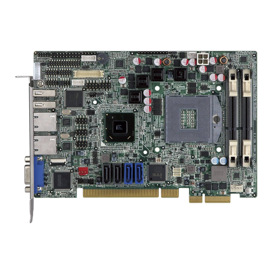
Page 13: Board Layout: Jumper And Connector Locations
Board Layout: Jumper and Connector Locations ( ( ( ( Unit:mm) ) ) )...
Need help?
Do you have a question about the PICOe-HM650 and is the answer not in the manual?
Questions and answers