Table of Contents
Advertisement
Quick Links
Download this manual
See also:
User Manual
Product Installation Guide
enterprise branch and head offices
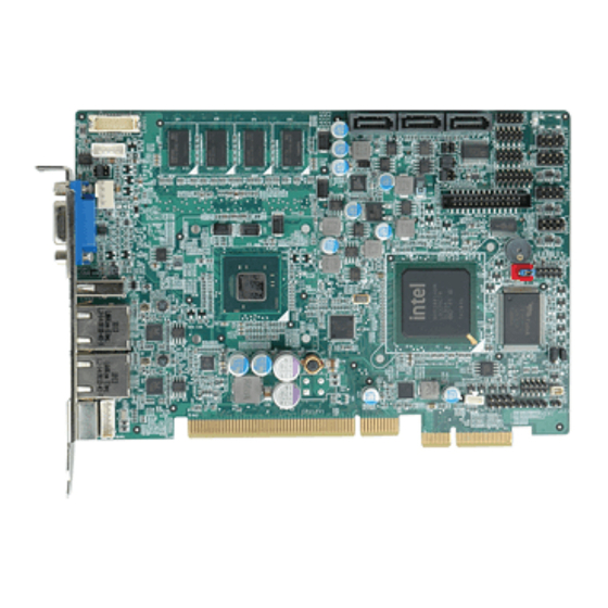
PICOe-PV
www.enochsystems.com
1-877-722-1116
sales@enochsystems.com
Copyright © 2013 Enoch Systems, LLC, Enoch Systems and the Enoch Systems logo are trademarks or registered trademarks of Enoch Systems, LLC and/or its affiliates in the U.S. and other countries.
Third-party trademarks mentioned are the property of their respective owners. All rights reserved.
Advertisement
Table of Contents

Summary of Contents for IEI Technology PICOe-PV-N4551
- Page 1 Product Installation Guide enterprise branch and head offices PICOe-PV www.enochsystems.com 1-877-722-1116 sales@enochsystems.com Copyright © 2013 Enoch Systems, LLC, Enoch Systems and the Enoch Systems logo are trademarks or registered trademarks of Enoch Systems, LLC and/or its affiliates in the U.S. and other countries. Third-party trademarks mentioned are the property of their respective owners.
-
Page 2: Quick Installation Guide
1 x Dual RS-232 Cable 3 x SATA Cable 1 x KB/MS Y Cable 1 x USB cable 1 x Mini Jumper Pack 1 x Utility CD(within manual) 1 x QIG (Quick Installation Guide) ©2007 Copyright by IEI Technology corp. All rights reserved. -
Page 3: Specifications
Specifications CPU: Intel® Atom™ D525 dual-core processor (1.80GHz/1MB L2 cache) Intel® Atom™ D425 single-core processor (1.80GHz/512KB L2 cache) Intel® Atom™ N455 single-core processor (1.66GHz/512KB L2 cache) System Chipset: Intel ICH8M BIOS: UEFILabel System memory: On-board 1GB DDR3 800MHz Memory; One 204-pin 800MHz DDR3 SDRAM SO-DIMM supported (system max. -
Page 4: Ordering Information
GbE, USB 2.0, SATA II, audio, RoHS PICOe-PV-D4251T-R11: Half-size PCIe CPU Card with Intel® Atom™ Single Core D425 1.80GHz/512KB L2, 1GB Memory on board, VGA/LVDS, Dual PCIe GbE, USB 2.0, SATA II, audio, TPM, RoHS PICOe-PV-N4551-R11: Half-size PCIe CPU Card with Intel® Atom™ Single Core N455... - Page 5 1.66GHz/512KB L2, 1GB Memory on board, VGA/LVDS, Dual PCIe GbE, USB 2.0, SATA II, audio, RoHS PICOe-PV-N4551T-R11: Half-size PCIe CPU Card with Intel® Atom™ Single Core N455 1.66GHz/512KB L2, 1GB Memory on board, VGA/LVDS, Dual PCIe GbE, USB 2.0, SATA II, audio, TPM, RoHS 19800-000075-RS:KB/MS Cable with Bracket 32200-015100-RS:LPT Cable 32102-000100-200-RS:SATA Power Cable...
-
Page 6: Jumpers Setting And Connectors
Jumpers setting and Connectors LABEL FUNCTION J_CMOS1 CMOS State Setting jumper JCF1 CF Card Master/Slave Setting jumper J_VLVDS1 LCD Voltage Selector jumper PCIE Status Selector jumper ATXCTL1 AT/ATX Power Mode Setting connector RS232/RS422 or RS485 Type Select Jumper RS422 or RS485 Type Select Jumper RS485 Termination select RS422 Termination select LVDS1... - Page 7 J_CMOS1: Clear CMOS Setup JCF1: CF Card Setup J_CMOS1 DESCRIPTION JCF1 DESCRIPTION Keep CMOS Setup Short Master (Default) (Normal Operation) Open Slave (Default) Clear CMOS Setup J_VLVDS1: Set The Panel Voltage JP1: PCIe interface Setup J_VLVDS1 DESCRIPTION J_PCIE1 DESCRIPTION Set The Voltage Level Of 1-2 Short Set up the interface Panel To 3.3V...
- Page 8 LVDS1: LVDS LCD Connector PIN NO. DESCRIPTION PIN NO. DESCRIPTION LVDSA_DATA0 LVDSA_DATA#0 LVDSA_DATA1 LVDSA_DATA#1 LVDSA_DATA2 LVDSA_DATA#2 LVDSA_CLK LVDSA_CLK# L_DDC_DATA L_DDC_CLK VCC_LCD VCC_LCD VCC_LCD VCC_LCD COM1, COM2,COM4: Internal Serial Port Connector PIN NO. DESCRIPTION PIN NO. DESCRIPTION CTS# DCD# DSR# DTR# RXD# RTS# TXD#...
- Page 9 USB0_1/USB2_3/USB4_5: USB Connector (PINHEADER2*4,8PIN,180,P:2.54MM) DESCRIPTION DESCRIPTION DATA0_N DATA1_P DATA0_P DATA1_N USB6: 1USB Connector (USB PORT,4PIN,90,p:2.00MM) DESCRIPTION DESCRIPTION DATA6_N DATA6_P J_AUDIO1: External Audio Module Connector DESCRIPTION DESCRIPTION HDA_SYNC HDA_BITCLK HDA_SDOUT SB_SPKR HDA_SDIN0 HDA_RST# VCC12 LPT1: Parallel Port Connector DESCRIPTION DESCRIPTION AUTO FORM FEED # PTD0 ERROR# PTD 1...
- Page 10 VGA1: D-SUB VGA,15PIN,90° ,2.29MM PIN DESCRIPTION PIN DESCRIPTION GREEN BLUN 10 DISPLAY_GND CRT_VCC 5VDDCDA 5VDDCLK DIO1: 10-pin Digital I/O Connector PIN DESCRIPTION PIN DESCRIPTION OUTPUT3 OUTPUT2 OUTPUT1 OUTPUT0 INPUT3 INPUT2 INPUT1 INPUT0 KB_MS1:6-pin Header PT1: MINIDIN JACK,6PIN,90° , Keyboard/Mouse Connector Keyboard/Mouse Connector DESCRIPTION DESCRIPTION...
- Page 11 BAT1 :Battery Connector CPU_FAN1: CPU Fan Connector DESCRIPTION DESCRIPTION BAT+ +12V BAT-(GND) FANIO1 FANPWM1 F_PANEL1 : External Switches and Indicators panel DESCRIPTION DESCRIPTION PWR_BTN+ PWR_LED+ PWR_BTN- PWR_LED- HDD_LED+ RESET+ HDD_LED- RESET- SATA1/SATA2/SATA3 : SATA WITH FRAME,7PIN,180° DESCRIPTION DESCRIPTION SATATXP1 SATATXN1 SATARXN1 SATARXP1 LAN1/LAN2 2 2 2 :...
-
Page 12: Board Layout: Jumper And Connector Locations
Board Layout: Jumper and Connector Locations ( ( ( ( Unit:mm) ) ) )... - Page 13 Board Layout: Jumper and Connector Locations (Unit:mm)


Need help?
Do you have a question about the PICOe-PV-N4551 and is the answer not in the manual?
Questions and answers