Table of Contents
Advertisement
Quick Links
Advertisement
Table of Contents

Related Manuals for AND AD-4401A


Summary of Contents for AND AD-4401A
- Page 1 AD-4401A Weighing Indicator INSTRUCTION MANUAL 1WMPD4003050...
- Page 2 No part of this publication may be reproduced, transmitted, transcribed, or translated into any language in any form by any means without the written permission of A&D Company, Limited. The contents of this manual and the specifications of the instrument covered by this manual are subject to change for improvement without notice.
-
Page 3: Table Of Contents
9.3. Check Weighing 3 ....................28 9.4. Check Weighing 4 ....................29 9.5. Check Weighing Functions..................29 10. CONTROL I/O ......................30 10.1. Pin Assignment ....................30 10.2. Connection Diagram.....................31 10.3. Control Input Method ...................32 10.4. Control Input Functions ..................33 10.5. Control Output Functions..................34 Page 1 AD-4401A... - Page 4 16.4. Output Functions ....................59 16.5. Analog 4-20 mA Output Functions ..............60 17. SETPOINT SETTING ....................61 17.1. Setting Using Key Switches................61 17.2. Setpoint Values List.....................63 18. CALIBRATION FUNCTION SETTING.................64 18.1. Calibration Functions....................66 19. GENERAL FUNCTION SETTING................68 19.1. Basic Functions....................70 AD-4401A Page 2...
- Page 5 20.6. Checking Setpoint Input ..................75 20.7. Checking Analog 4-20 mA Output..............76 20.8. Checking Load Cell Input..................76 20.9. Checking Software Version .................76 21. INITIALIZATION ......................77 21.1. Parameter Initialization..................77 21.2. General Function Initialization ................77 21.3. All Data Initialization ....................78 22. SPECIFICATIONS.......................79 Page 3 AD-4401A...
-
Page 6: Safety Precautions
1. SAFETY PRECAUTIONS For safe and correct usage, read the following precautions carefully before using the indicator. Precautions for designing WARNING ● Provide an external safety circuit to the indicator so that the safety of the whole system can be secured even if errors occur in the external power supply or in the indicator. -
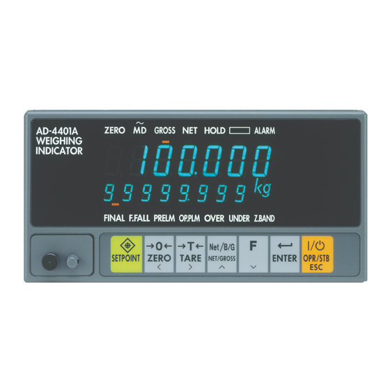
Page 7: Part Names
Optional preliminary Full when performing Overweight Overweight loss-in-weight Underweight Underweight Hi-Hi batching or Near-zero (Z.BAND) Near-zero (Z.BAND) check weighing. CAL (Calibration) key SETPOINT ZERO TARE Key Switches NET/GROSS Function ENTER ON/OFF Rating label (Accessory) Other Sealing cover Page 5 AD-4401A... -
Page 8: Rear Panel
AC power input terminal block Protective conductor terminal Slide rail 2.3. Accessories Name Quantity Terminal block cover Terminal block cover securing screw Connector for the CONTROL I/O Connector for the SER.OUT Panel mount packing Rubber foot Rating label Status label AD-4401A Page 6... -
Page 9: Installation To Control Panel
Make a hole in a control panel as shown below. Panel thickness: 1.6 to 3.2 Unit: mm Remove the slide rails on both sides and insert the AD-4401A with the accessory packing through the hole into the panel. Insert the slide rails from behind. -
Page 10: Connection To Power Supply
4. CONNECTION TO POWER SUPPLY 4.1. AC Power Input Terminal Assignment Terminal No. Symbol Description Ground terminal AC power input (Neutral) Earthed conductive part AC power input (Live) Unearthed conductive part 4.2. Connection Diagram Live Neutral AD-4401A Page 8... -
Page 11: Connection To Load Cell
Symbol Description EXC+ Load cell excitation voltage + SEN+ Sensing input + SEN- Sensing input - EXC- Load cell excitation voltage - SIG+ Load cell signal input + SIG- Load cell signal input - SHLD Frame ground Page 9 AD-4401A... -
Page 12: Connection Diagram
Load cell excitation voltage - Sensing - Load cell signal - ●4-wire connection As shown in the figure below, short-circuit the terminals No.1 and No.2, and terminals No.3 and No.4. Shield Load cell excitation voltage + Load cell signal +... -
Page 13: Calibration
6. CALIBRATION Calibrates the AD-4401A to convert the signal from the load cell to a mass value correctly. 6.1. Calibration Setting Set the following calibration functions which are required for calibration using calibration weights. ●Unit: (CALF-01) Select the unit of the scale. -
Page 14: Calibration Using Calibration Weights
Zero calibration Press the ENTER key when the STABLE (MD) status is turned OFF. Dashes are displayed in the sub-display and zero calibration is performed. Note: When the Function key is pressed, the AD- 4401A proceeds to span calibration without performing zero calibration. - Page 15 Check if unnecessary load is applied to the load cell. The load cell signal voltage at zero calibration is less than 0 mV/V. Check if load cell connections of SIG+ and SIG- are not reversed. The calibration weight value that is set in span calibration exceeds the maximum capacity.
-
Page 16: Basic Weighing Functions
7. BASIC WEIGHING FUNCTIONS When the AD-4401A is powered ON, all the segments of the display turn ON and OFF to check the display. Then the AD-4401A enters the normal mode and starts weighing. If the AD-4401A is powered OFF during the OFF mode (with the display OFF), the AD-4401A will be in the OFF mode when powered ON. - Page 17 The NET status turns ON when the net value is displayed. Operation: NET/GROSS key, Control input ●Zero Center of zero is detected and the ZERO status turns ON when the gross value is within 1/4 of the minimum division. ●Stable Stability is detected when the weight value is maintained within the stability detection width (CALF-09) during the stability detection time (CALF-08).
- Page 18 ●Total clear The total weight and the number of accumulations are cleared. Operation: Function key (FncF-02), Control input ●Undoing accumulation The weight value accumulated last is subtracted from the total weight. Operation: Function key (FncF-02), Control input ●Alarm Select the condition to turn the ALARM status ON (FncF-10) from the following:...
-
Page 19: Batch Weighing Functions
When the small flow comparison disable time (Sq F-12) has passed and the weight value has exceeded the free fall value, the small flow output turns OFF. When the judging delay time (Sq F-13) has passed and the weight value is stable (Sq F-07), the weight value is judged. - Page 20 T2: Large flow comparison disable time T3: Medium flow comparison disable time T4: Small flow comparison disable time T5: Judging delay time T6: Weighing end output time T7: Discharge start input delay time T8: Discharge end delay time AD-4401A Page 18...
- Page 21 When the weight value is judged to be underweight, the small flow output turns ON. When the correction flow ON time (Sq F-16) has passed, the small flow output turns OFF. When the correction flow OFF time (Sq F-17) has passed and the weight value is stable (Sq F-07), the weight value is judged.
-
Page 22: Loss-In-Weight Batching
When the small flow comparison disable time (Sq F-12) has passed and the – weight value has exceeded the free fall value, the small flow output turns OFF. When the judging delay time (Sq F-13) has passed and the weight value is stable (Sq F-07), the weight value is judged. - Page 23 Medium flow output Small flow output Weighing end output OK/Over/Under output T1: Weighing start input delay time T2: Medium flow comparison disable time T3: Small flow comparison disable time T4: Judging delay time T5: Weighing end output time Page 21 AD-4401A...
- Page 24 When the weight value is judged to be underweight, the small flow output turns ON. When the correction flow ON time (Sq F-16) has passed, the small flow output turns OFF. When the correction flow OFF time (Sq F-17) has passed and the weight value is stable (Sq F-07), the weight value is judged.
-
Page 25: Sequential Weighing Functions
(Si F-02) or options (bCdF-02, rS F-02). ●Emergency stop The large flow, medium flow and small flow outputs turn OFF, the weighing sequence error output turns ON and the indicator waits for the next weighing start input. Operation: Function key (FncF-02), Control input ●Flow timeout error/Discharge timeout error... - Page 26 Waits for the weight value to be near-zero. Starts the correction flow. Turns the small flow output ON for correction. Waits for the correction flow ON time to pass and turns the small flow output OFF. Waits for the correction flow OFF time to pass.
-
Page 27: Simple Comparison Normal Batching
8.4. Simple Comparison Normal Batching When the weight value is compared with the setpoint and the condition is met, the control output turns OFF. Condition Control output Weight value Near-zero (Sq F-25) Near-zero Weight value Final - Optional preliminary Large flow Weight value ... -
Page 28: Weighing Sequence Functions
Discharge start input delay time 0.0 to 30.0 s Discharge end delay time 0.1 to 30.0 s 0: None Discharge timeout time 1: 1 to 86400 s Add the final weight to the near-zero 0: Disable setpoint value 1: Enable AD-4401A Page 26... - Page 29 Comparison target for the near-zero 2: |Gross value| value 3: Net value 4: |Net value| Comparison target excluding the near- 1: Gross value zero and full values 2: Net value 0: Disable Automatic tare at weighing start 1: Enable Page 27 AD-4401A...
-
Page 30: Check Weighing Functions
Check weighing separates the weight values into a maximum of five stages. Select a weighing mode (CALF-14) from the following. 9.1. Check Weighing 1 When the weight value is compared with the setpoint and the condition is met, the control output turns ON. Condition Control output Gross value ... -
Page 31: Check Weighing 4
●Automatic print When the weight value is five times the minimum division or more and is stable, data is output once from the standard serial output or options. To output again, wait for the weight value to be four times the minimum division or less. -
Page 32: Control I/O
10. CONTROL I/O 10.1. Pin Assignment The applicable connector is an FCN-360 series 16-pin female connector manufactured by Fujitsu Component Limited or the equivalent. An FCN-361J016 (connector) and an FCN-360C016 (cover) are provided with the indicator. Pin No. Description Description Pin No. -
Page 33: Connection Diagram
- OFF current: 1 mA or less Internal Circuit 3.3 kΩ Control output - Maximum load voltage: 30 VDC - Maximum load current: 50 mA/point - Voltage drop at ON: 1 V or less - Leakage current at OFF: 0.1 mA or less Page 31 AD-4401A... -
Page 34: Control Input Method
10.3. Control Input Method Two methods of control input are available; edge detection and level detection. Edge detection Control input is performed when the control input is turned ON (short-circuit) from the OFF state (open- circuit). The pulse width is 50 ms or more. -
Page 35: Control Input Functions
19: Weighing restart 20: Pause 21: Forced weighing end 22: Forced discharge end 23: Error clear 24: ON=Select loss-in-weight batching OFF=Select normal batching 25: Manual correction flow (One-shot small flow) 26: ON=Checking weighing start OFF=Checking weighing stop Page 33 AD-4401A... -
Page 36: Control Output Functions
17: When tare fails 18: When zero setting or tare fails 19: Total weight / number of accumulations overflow 20: When the judgment result is OK 21: Hold 22: ON = loss-in-weight batching / Off = Normal batching AD-4401A Page 34... -
Page 37: Setpoint Input
Component Limited or the equivalent. The connector is not provided and must be supplied by the user. The descriptions of the pin Nos. depend on the weighing mode (CALF-14) and the setpoint setting method (SP F-01) settings. In addition, when the minimum division (CALF-03) is 10 d or more, the setpoint will be ten times the setting value. - Page 38 Lo limit 10^0 BCD input 8 Lo limit 10^1 Target 10^0 Lo limit 10^2 Target 10^1 Lo limit 10^3 Target 10^2 Lo limit 10^4 Target 10^3 Target 10^4 Hi limit 10^0 Hi limit 10^1 Hi limit 10^2 Shield AD-4401A Page 36...
- Page 39 Hi-Hi limit 10^0 Lo-Lo limit 10^0 Hi-Hi limit 10^1 Lo-Lo limit 10^1 Hi-Hi limit 10^2 Lo-Lo limit 10^2 Hi-Hi limit 10^3 Lo-Lo limit 10^3 Hi limit 10^0 Hi limit 10^1 Hi limit 10^2 Hi limit 10^3 Shield Page 37 AD-4401A...
-
Page 40: Connection Diagram
- Voltage drop at ON: 1 V or less - Leakage current at OFF: 0.1 mA or less Key scan input - ON voltage: 1 V or less - ON current: 3 mA or more - OFF current: 1 mA or less AD-4401A Page 38... -
Page 41: Setpoint Input Functions
For the function setting procedure, refer to “19. GENERAL FUNCTION SETTING.” SP F- Item Setting Value Default Setpoint setting 0: Setpoint input not used method 1: 5-digit input from external devices 2: 16-digit input from external devices Page 39 AD-4401A... -
Page 42: Standard Serial Output
Signal level Current loop 0 to 20 mA Baud rate (Si F-03) 600, 2400 bps Character bit length 7 bits Parity Even Star bit length 1 bit Stop bit length 1 bit Code ASCII Terminator CR LF AD-4401A Page 40... -
Page 43: Communication Functions
5: Gross value + Net value + Tare value 6: Total weight 7: Number of accumulations 8: Total weight and number of accumulations 1: Interval output at the display update rate (FncF-03) 2: In synchronization with automatic print Data output timing... -
Page 44: Bcd Output
13. BCD OUTPUT 13.1. Pin Assignment The applicable connector is an FCN-360 series 40-pin female connector manufactured by Fujitsu Component Limited or the equivalent. An FCN-361J040 (connector) and an FCN-360C040 (cover) are provided with this option. Pin No. Description Description Pin No. -
Page 45: Connection Diagram
- Voltage drop at ON: 1 V or less - Leakage current at OFF: 0.1 mA or less Hold input - ON voltage: 1 V or less - ON current: 3 mA or more - OFF current: 1 mA or less Page 43 AD-4401A... -
Page 46: Output Functions
2: In synchronization with automatic print 3: In synchronization with manual print 1: Positive logic (Open-circuit is ON) Data output logic 2: Negative logic (Short-circuit is ON) 1: Positive logic (Open-circuit is ON) Strobe output logic 2: Negative logic (Short-circuit is ON) AD-4401A Page 44... -
Page 47: Rs-422/485
Disable the terminal resistor Short-circuited to No. 4: Enable the terminal resistor Signal ground 14.2. Connection Diagram 14.2.1. RS-422 AD-4401A Master 1 Send data + 2 Send data - 3 Receive data + 4 Receive data - 5 Terminal resistor 100 Ω... - Page 48 14.2.2. 2-wire RS-485 Short-circuit the terminals No.1 and No.3, and the terminals No.2 and No.4 as shown below. Terminal resistors must be installed on both ends of the circuit. AD-4401A (Slave address 1) Master AD-4401A (Slave address 2) AD-4401A (Slave address 3) 100 Ω...
-
Page 49: Communication Specifications
3: In synchronization with manual print 4: Response to command 5: Interval output of comparison result and gross value at 100 times/s. 6: Interval output of comparison result and net value at 100 times/s. 7: In synchronization with automatic/manual accumulation... -
Page 50: Format When Data Output Timing (Rs F-02) Is 1, 2, 3 Or 7
+ SP SP SP SP . SP SP Positive overload (rS F-01) - SP SP SP SP . SP SP Negative overload SP SP None SP g Unit SP t No unit is added when the number of accumulations is output. AD-4401A Page 48... -
Page 51: Format When Data Output Timing (Rs F-02) Is 5 Or 6
Gross value (rS F-02=5) Net value(rS F-02=6) 0 0 0 0 7 F Output weight value (rS F-01) SP SP None SP g Unit SP t *1 and *2: For the detailed description, refer to the next page. Page 49 AD-4401A... -
Page 52: Format When Data Output Timing (Rs F-02) Is 8
Small flow/Lo-Lo Discharge Weighing end *2: The gross value and the net value are converted from a signed decimal number into a 6-digit hexadecimal number. Negative numbers are represented by the two's complement. A decimal point is not included. Decimal Hexadecimal …... -
Page 53: Format When Data Output Timing (Rs F-02) Is 4
Data format is the same as that when data output timing (rS F-02) is 1, 2, 3 or 7. Refer to “14.5. Format When Data Output Timing (rS F-02) is 1, 2, 3 or 7” for the weight data format. Page 51 AD-4401A... - Page 54 Optional preliminary/Full/Lo limit 0 1 8 0 0 0 18.000 kg Overweight/Lo-Lo limit 0 0 0 0 2 0 0.0020 kg Underweight 0 0 0 0 2 0 0.0020 kg Near-zero 0 0 0 2 0 0 0.0200 kg AD-4401A Page 52...
- Page 55 M N : Display net value in the main display B B : Weighing start B D : Discharge start H B : Emergency stop When the command above is sent, the command is echoed back and is executed. Master Command AD-4401A...
- Page 56 When writing setpoint values, set the setpoint setting method (SP F-01) to 0 (Setpoint input not used). S S : Write setpoint values When the command above is sent, the command is echoed back. Then, when setpoint data is sent, the data is echoed back and saved. Master Command...
-
Page 57: Rs-422/485, Rs-232C Functions
4: Response to command 5: Interval output of comparison result and gross value at Data output timing 100 times/s 6: Interval output of comparison result and net value at 100 times/s. 7: In synchronization with automatic/manual accumulation 8: Interval output at 100 times/s... -
Page 58: Rs-232C
15. RS-232C 15.1. Pin Assignment The applicable connector is a D-sub 25-pin male connector. The locking screw is M2.6. The connector is not provided and must be supplied by the user. Pin No. Description 9 to 19 21 to 25... -
Page 59: Connection Diagram
Parity (rS F-04) None, Odd, Even Start bit length 1 bit Stop bit length (rS F-06) 1, 2 bits Code ASCII Terminator (rS F-07) CR LF, CR 15.4. Communication Functions Refer to “14. RS-422/485” for communication functions. Page 57 AD-4401A... -
Page 60: Analog 4-20 Ma Output
Analog current output - SHLD Frame ground When the optional analog 4-20 mA output is not installed, the terminals No.8 and No.9 are vacant. Check the 07 column of the option list on the side of the indicator casing. 16.2. Connection Diagram... -
Page 61: Output Specifications
- Net value ●Output adjustment Output characteristic is represented by the straight line obtained by connecting between the weight value at 4 mA output (An F-02) and the weight value at 20 mA output (An F-03). Output current 20 mA... -
Page 62: Analog 4-20 Ma Output Functions
An F- Item Setting Value Default 1: Displayed weight value Output weight value 2: Gross value 3: Net value Weight value at 4 mA output -999999 to 9999999 -999999 to 9999999 Weight value at 20 mA output 20000 AD-4401A Page 60... -
Page 63: Setpoint Setting
Normal mode SETPOINT key Goes to the item selection mode. Item selection Selects the blinking item in the lower status display and goes to the inputting ENTER key mode of the item. TARE key Shifts the blinking item in the lower status display to the right. - Page 64 Normal mode Select an item Save Cancel Input a setting value AD-4401A Page 62...
-
Page 65: Setpoint Values List
Weighing mode: Check weighing 1/2/3/4 Attach the accessory status label on the lower status display. Status display Item Setting value Blinking Z.BAND Near-zero Blinking Lo-Lo Lo-Lo Blinking Lo -999999 to 9999999 Blinking Go Blinking Hi Blinking Hi-Hi Hi-Hi Page 63 AD-4401A... -
Page 66: Calibration Function Setting
Cal 5et When “ ” is displayed, press the NET/GROSS key. Cal fnc When “ ” is displayed, the indicator has entered the calibration function mode. Press the ENTER key to go to the item selection mode. AD-4401A Page 64... - Page 67 Operation in the calibration function mode: Item selection ENTER key Selects the displayed item and goes to the inputting mode of the item. TARE key Shifts the blinking item to the right. ZERO key Shifts the blinking item to the left.
-
Page 68: Calibration Functions
4: 2.0 d Zero tracking width 5: 2.5 d 6: 3.0 d 7:3.5 d 8:4.0 d 9:4.5 d 0.0: Not used Stability detection time 0.1 to 5.0 s 0: Not used Stability detection width 1 to 9 d AD-4401A Page 66... - Page 69 CALF- Item Setting Value Default 0: Disable Tare and zero setting at unstable weight 1: Enable 0: Disable Tare at negative gross value 1: Enable Standard serial output, when the weight value 0: Disable is overloaded or unstable. 1: Enable...
-
Page 70: General Function Setting
19. GENERAL FUNCTION SETTING Set the general functions in the general function mode. Select a function to be set and press the ENTER key to go to the item selection mode. Select a function to be set Basic function Reserved internally... - Page 71 Operation: Item selection ENTER key Selects the displayed item and goes to the inputting mode of the item. TARE key Shifts the blinking item to the right. ZERO key Shifts the blinking item to the left. NET/GROSS key Increases the blinking digit by one.
-
Page 72: Basic Functions
10: Discharge start 11: Forced weighing end 12: Forced discharge end 13: Error clear 14: Manual correction flow 15: Normal/Loss-in-weight batching selection 17: Accumulation 18: Undoing accumulation 1: 20 times/s Display update rate 2: 10 times/s 3: 5 times/s AD-4401A Page 70... - Page 73 3: 5.6 Hz digit: Post-digital filter cutoff 4: 4.0 Hz frequency 5: 2.8 Hz Pre-digital filter and post-digital filter 6: 2.0 Hz are connected in series. 7: 1.4 Hz 8: 1.0 Hz 9: 0.7 Hz 101: 11.0 Hz (HPDF) 102: 8.0 Hz (HPDF) 103: 5.6 Hz (HPDF)
- Page 74 0: Disable Comparison at hold 1: Enable 00000000: None 00000001: Overload 00000010: Total weight / number of Condition to turn the ALARM status accumulations overflow 00000111 00000100: Zero setting error 00001000: Tare error 00010000: Weighing sequence error AD-4401A Page 72...
-
Page 75: Operation Checking
20. OPERATION CHECKING Operations are checked in the checking mode. Select an operation to be checked and press the ENTER key. Select an operation to be checked Key switches Control input/output Software version Standard serial output Load cell input BCD output... -
Page 76: Checking Key Switches
When the NET/GROSS key or Function key is pressed, the corresponding pin No. of the control output B1 to B6 turns ON. B1 to B6 20.3. Checking Standard Serial Output When the ENTER key is pressed, “123” is sent. The communication specifications comply with the standard serial output specifications. AD-4401A Page 74... -
Page 77: Checking Bcd Output
20.4. Checking BCD Output When the hold input turns ON, “0” turns to “1” and the output of the displayed pin No. turns ON. Press the NET/GROSS key or Function key to switch pin Nos. Hold input Pin No. 20.5. Checking RS-422/485, RS-232C When the ENTER key is pressed, “123”... -
Page 78: Checking Analog 4-20 Ma Output
Press the NET/GROSS key or Function key to increase or decrease the current value. 2 mA output 20 mA output 20.8. Checking Load Cell Input The load cell signal voltage (mV/V) is displayed in the sub-display. 20.9. Checking Software Version The AD-4401A software version is displayed in the sub-display. AD-4401A Page 76... -
Page 79: Initialization
21. INITIALIZATION 21.1. Parameter Initialization Power ON While holding the SETPOINT key, turn the AD-4401A With the display shown to the left, press the ENTER key. With the display shown to the left, hold the ENTER key for three seconds or more to initialize the parameters below. -
Page 80: All Data Initialization
When “ ” is displayed, press the ENTER key. With the display shown to the left, hold the ENTER key for three seconds or more to initialize the parameters described in 21.1., general functions and calibration functions AD-4401A Page 78... -
Page 81: Specifications
22. SPECIFICATIONS Dimensions 144 (W) x 72 (H) x 197 (D) mm -10 °C to 40 °C Operating temperature and humidity range Less than 85%RH, non-condensing When the indicator is secured to the control panel: IP rating Outside of the control panel: IP65... -
Page 82: External Dimensions
External dimensions パネルカット寸法 Panel cutout dimensions 板厚 1.6~3.2 Panel thickness: 1.6 to 3.2 Unit: mm AD-4401A Page 80... - Page 84 3-23-14 Higashi-Ikebukuro, Toshima-ku, Tokyo 170-0013, JAPAN Telephone: [81] (3) 5391-6132 Fax: [81] (3) 5391-6148 A&D ENGINEERING, INC. 1756 Automation Parkway, San Jose, California 95131, U.S.A. Telephone: [1] (408) 263-5333 Fax: [1] (408)263-0119 A&D INSTRUMENTS LIMITED Unit 24/26 Blacklands Way, Abingdon Business Park, Abingdon, Oxfordshire OX14 1DY United Kingdom Telephone: [44] (1235) 550420 Fax: [44] (1235) 550485 A&D AUSTRALASIA PTY LTD...
Need help?
Do you have a question about the AD-4401A and is the answer not in the manual?
Questions and answers