Advertisement
組立前に必ずこの説明書を最後まで、よくお読みにな
り、正しくお使い下さい。特に、「1.組立を始める前
に必ずお読み下さい」は、組立前及び飛行前に必ずお
読み下さい。
この説明書は、大切にお手元に保管して下さい。
製品改良のため、予告なく仕様を変更する場合があります。
Before assembly, make sure to completely read this
instruction manual. In particular, make sure to read the
"1.Read before assembly" section before assembly and
operating the unit.
Keep this instruction manual in a handy, safe place.
In
order
to
make
improvements
specifications may be altered without prior notice.
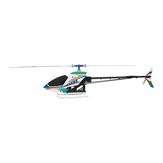
主要諸元
全備重量
ギヤ比
無線機
適合エンジン
to
this
product,
SPEC
約
/
4,700g
Overall weight
/ 7.92 : 1 : 5
Gear ratio
ヘリ用プロポセット (別売)
/
Radio controller
Radio set for model helicopter (Not included)
80∼91クラス (別売)
/
Engine
∼
80
※(マフラー別売)
205mm
428mm
MADE IN JAPAN
Approx. 4,700g
91 Class (Not included)
(Muffler isn't included)
1,400mm
2003
C
No.10991
Advertisement
Table of Contents

Related Manuals for Hirobo SST-EAGLE3-WC


Summary of Contents for Hirobo SST-EAGLE3-WC
- Page 1 主要諸元 SPEC 組立前に必ずこの説明書を最後まで、よくお読みにな 約 4,700g Approx. 4,700g 全備重量 Overall weight り、正しくお使い下さい。特に、「1.組立を始める前 / 7.92 : 1 : 5 ギヤ比 Gear ratio ヘリ用プロポセット (別売) 無線機 Radio controller に必ずお読み下さい」は、組立前及び飛行前に必ずお Radio set for model helicopter (Not included) 80∼91クラス (別売) 読み下さい。 適合エンジン Engine ∼...
- Page 3 Read before assembly For safety reasons, observe the following precautions before assembly. Thank you very much for purchasing a Hirobo product. In order to be このたびは、ヒロボー製品をお買上げいただき、ありがとうござい able to use this product safely, please read this manual before flying the ます。...
- Page 4 (オイル / グリス)、送・受信機用バッテリーが充分に充電されて or at the engineering services section of Hirobo’s Sales Department. いるかを点検してください。 Before starting the engine, make sure that there are no loose screws, that all 8.
- Page 5 WARNING FUEL 1. 模型用エンジンは模型専用のグロー燃料が必要です。 1. Only use GLOW fuel for model engines. ◆ ガソリンや灯油は使用できません。 Gasoline or kerosene may cannot be used. ◆ グロー燃料は揮発性が高く引火しやすいので取り扱いには十分注 GLOW fuel is highly volatile and flammable. Handle with care. 意してください。 Use properly in accordance with the type of engine. (ABC or ring fitted) ◆...
- Page 6 ◆ 乾燥した場所で、幼児の手の届かないところに保管してくださ い。 3. Inquire about repairs at the store from where you purchased the product or 3. 修理は、お買上げの販売店、またはヒロボー(株)営業本部エンジニ at the engineering services section of Hirobo’s Sales Department. アリングサービスにお申し付けください。 Individuals lacking proper knowledge or tools necessary for repairs may ◆ 修理の知識のない方や専用工具を持っていない方が修理をする...
- Page 7 For safe handling of the radio controlled helicopter 先に、 無線操縦エンジン模型として共通の注意事項を述べましたが、 ヘ In addition to the standard precautions previously mentioned regarding radio リコプターの場合、さらに次に述べる注意事項を守ってください。 controlled engines, please observe also the following precautionary items which are specific to helicopters. WARNING 実機の場合、飛行前には厳しい点検が義務付けられています。無線操 For real aircraft, strict pre-flight inspections are mandatory. The radio controlled 縦(R/C)ヘリコプターは小型で手軽に飛行させることができますが、...
- Page 8 WARNING In-flight safety check 1. エンジンを始動するときは周辺に当たるものや、 巻き込まれそうな 1. Check that there are no objects in the surrounding area that may get ものがないか確認してください。 entangled or struck by the unit. 2. 周囲に同じ周波数の使用者がいないことを確認して、 送信機→受信 2. Check that there are no other operators in the surrounding area using the 機の順番にスイッチを入れ、...
- Page 9 Swash plate assembly (Pre-assembled into our factory) WARNING Due to a lack of proper testing, please acknowledge that Hirobo will not take responsibility for accidents resulting from remodeling the unit or from the replacement of parts with those not manufactured by Hirobo.
- Page 10 How to read part types and sizes 本説明書の文中に記載している記号は、次の約束になっています。 The symbols shown in this instruction manual are shown as below: ● 単位はミリメートルです。以下、文中で長さなどに表示されてい The unit of measurement is the millimeter. The lengths, etc. shown る単位はミリメートルです。 in the following are indicated in millimeters. ナベ頭ビス...
- Page 11 コントロールアンプ Control amplifier 2513-040 2513-072 ´525 (500) ´2,940 (2,800) エンジンスターター用 エンジンプラグヒート用 グロープラグコード ヒロボー 燃料 Booster cables HIROBO RC Fuel For Helicopter & Airplane バッテリー バッテリー 12V engine Engine plug heating starter battery battery ニトロメタン(オイル約 ) 15%Nitromethan (approx.20%oil) 2515-200 ´4,200 (4,000) ニトロメタン(オイル約...
- Page 12 Useful tools あると便利な周辺用具 ¥税込価格(税抜価格) * The prices in parentheses are the prices excluding consumption tax. ブレードサポート プラグレンチ フライホイールレンチ メカクッションパッド プーラー 2513-025 Blade support Plug wrench Fly wheel wrench RC mechanical cushion pad Puller ´2,625 (2,500) 2513-026 ´1,050 (1,000) ピンク 2513-052 ( /Pink) ´525 (500) キイロ...
-
Page 13: Fuel Tank Assembly
Assembly Elevator lever assembly M2ロ ッ ト エン ド ……………2 M2 rod end ① エレベータレバー Assy に M2X15CS を取付け M2ロッドエンド ます。 M2X15CS ………………2 M2 rod end ② ロッドエンドをネジ込みます。 (完全にねじ込んでください) Attach M2 ball links and arm bosses to the elevator ピボ ッ ト ボル ト ø5X12.5XM3 …2 lever with M2X15CS. - Page 14 エンジン周辺部品の着脱に便利な下記の工具を取り揃えております。是非ご利用下さい。 お知らせ Hirobo highly recommends the tools listed below for easy attachment and removal of the fan hub assembly. Please check with your local Information distributor for price and availability. 税込価格(税抜価格) * The prices in parentheses are the prices excluding consumption tax.
- Page 15 Engine assembly M3X6皿ビス ………………4 M3X6 countersunk screw ① エンジン付属のドライブワッシャーとワッシャーを Remove drive washer and washer which is attached to 取外します。 engine. ② エンジン軸に FWø10Xø18X1.5・テーパーカラー・ス Put starter pulley and starter pulley washer on engine axis タータープーリー ・ スタータープーリー座金を入れ、 and fasten them with drive nut which is part of the engine M4X15CS ………………4 エンジン付属のドライブナットで締付けます。...
- Page 16 Attachment of cooling cover ① エンジンキャブレター部のクーリングカバーを下図 Cut the cooling cover to clear the carburetor as shown below. の様にカットします。 ② クーリングカバー R・ L、ボス部を約 2.5mm カット Cut cooling cover at its R and L boss areas by approx. します。 2.5mm. ③ その他の部分で、ご使用になるエンジンとクーリン If interference of the engine and the cooling cover occurs in グカバーの干渉が生じる場合は、その部分のカット...
-
Page 17: Frame Assembly
フレームの組立 Frame assembly ■ サーボフレームの組立 Servo frame assembly ① マストベアリングホルダー、 ベアリングマウント、 カ …………………… M3X8CS Fasten the mast bearing holders, the bearing mount holder, ウンターギヤ第 1 軸 ASSY、 カウンター第 2 軸 ASSY、 the counter gear first shaft assembly, the counter second エレベーターレバーを下図のネジで締め付けます。... - Page 18 Frame assembly M3X8CS ……………… 8 Main frame assembly メインフレームに防振ゴムφ 10、φ 5 を取り付けま ① Attach the rubber cushion Ø10,Ø5 to the Main frame. M3X 10 CS ……………… 8 す。 Fasten the engine assembly, the M3X64 cross members エンジンASSY、 M3×64クロスメンバー、 EXフロー ② and the (L) angles onto the main frame with the screws ティングアングル...
- Page 19 Frame assembly ① サーボフレームを定盤の上に置いて、水平、垂直を Place the servo frame on a surface plate and tighten the 出し、ネジを完全に締込みます。 screws completely after adjusting the level and the ② サーボフレームにネジを締め込んだ後、ロアフレー perpendicularity. ムを組込み、定盤の上に置いて、水平、垂直を出し、 Assemble the lower frame after tightening the screws into ロアフレームのネジを完全に締込みます。 the servo frame. Place the lower frame on a surface plate and tighten the screws of the lower frame completely after ………………...
- Page 20 Lever assembly ・ 下図に従ってΙ型レバー、エルロンレバーを組み立 • Following the diagrams below, assemble the two I-type てます。 levers and the Aileron lever. ……………… I-type lever assembly (2 sets) Aileron lever assembly M2X6CS EXø5ボール EXø5 ball EX φ 5ボール ……………… FWø1.7 EX¿5 ball M2X6CS I型レバー...
- Page 21 VPUS(Variable servo frame pitch up system) VPUS(Variable servo frame pitch up system) assembly ・ 下図に従って組み立てをします。 • Assemble, following the diagrams below, M3X25CS …………………2 ・ メインマストを取り付け、エレベーター Assy のスラ • Attach the main mast and assemble the slide ring, ensuring イドリングが軽く上下するように組立をしてくださ that it moves easily up and down. い。...
- Page 22 Attachment of the mechanical plate and the tail boom holder テールブームホルダー Tail boom holder M3X35CS ………………2 FWø2.6Xø7X0.5 M3X10CS ………………2 M3ナイロンナット M3X35CS (仮組み) M3X8CS ………………4 (Temporarily tighten) M3X8CS M3X8TS ………………4 FWø2.6Xø7X0.5 FWø2.6Xø7X0.5 (仮組み) (Temporarily tighten) M3ナイ ロ ンナ ッ ト …………1 M3Uナット...
-
Page 23: Landing Gear Assembly
Landing gear assembly ① スキッドフットに M2 × 6CS でロッドエンド M2 × Fixed the rod end M2X12.5 (for the antenna guide) to the ………………4 M3X6CS 12.5 を固定します。 (アンテナガイド用) skid foot with M2X6CS. ② スキットバンドにスキットパイプを通し、 M3×8C Pass the skid pipes through the skid bands and fix with S、M... - Page 24 Assembling the washout assembly ウォッシュアウトコントロールアームにピボット ○ ボルト(E)を取付けます。 ピボットボルトE ……………2 Pivot bolt (E) Attach pivot bolts (E) to the washout control arm. ピボットボルトE Pivot bolt (E) Main mast assembly M2.6X12CS M3X8 CS …………………2 M2.6X6 CS ………………1 EXメインギヤ95T EX main gear 95T カラー...
-
Page 25: Rotor Head Assembly
Rotor head assembly Attachment of the mixing arm and the ① ミキシングアームにφ 5 ボール台付を M2 × 6CS seesaw で取付けます。 Attach the ø5 ball with stand to the mixing arm ……………… M2.6X15CS ② シーソーをセンターハブに M3 × 8 ボタンボルト with M2X6CS. で取付けます。 Attach the seesaw to the center hub with M3X8 button …………………... - Page 26 Attachment of the stabilizer blade Caution M3X3SS …………………4 Balance the stabilizer blade and adjust by winding tape, etc. around the lighter side. スタビライザーブレード Stabilizer blade M3X3SS Stabilizer plate: Attach the stabilizer bars so that they are ○ スタビライザーブレードは左右同じ位置に取り付け in the same position to the left and right. A=B Standard てください。A = B 標準長さ 115mm ±...
- Page 27 Attachment of the drag metal and blade spacer Pass ø5 drag metals through the blade holder and screw ø5 ドラッグメタルをブレードホルダーに通し、ブ ○ in the blade spacers. (Screw locking agent must be used.) レードスペーサーをネジ込みます。 (ネジロック剤 使用) To tighten, insert M4 nut into each drag metal and tighten with a spanner wrench.
-
Page 28: Tail Boom Brace Assembly
Assembling the tail gear assembly ① テールギヤ ASSY に EX φ 5 ボールを M2 × 6CS で固 Fix an EX ø5 ball to the tail gear assembly with M2X6CS. M3X3SS …………………1 定します。 M2X6CS …………………1 EXφ5ボール ………………1 EXø5 ball ユニバーサルピン Universal pin ユニバーサルピン... - Page 29 テールブームの取付 Attachment of the tail boom ① 8角テールブームをテールブームホルダーに入れ、 仮 Insert the octagonal tail boom into the tail boom holder 組の M3 × 20CS で締付けます。 and fasten provisionally with M3X20CS. ② 8 角テールブームにテールギヤ ASSY を取付け、M3 M3X5CS …………………4 Attach the tail gear assembly to the octagonal tail boom ×...
- Page 30 尾翼の取付 Attachment of the tail fin M3X35CS ………………… M3X35CS FWø3Xø9X1 ……………… M3X25CS 水平尾翼 Horizontal stabilizer ………………… M3X18CS M3ナイ ロ ンナ ッ ト ………8 尾翼バンド(U) M3 nylon nut Stabilizer band (U) M3X25CS ……………… FW¿3X¿9X1 テールブームブレースバンド(U) Tail boom brace (U) …… FW¿2.6X¿7.5X0.5 尾翼バンド(L) カ...
- Page 31 Servos installation M2.6X18PH ………………2 サーボプレート M2.6X10CS ………………8 Servo plate サーボの種類によっては使用しません。(JR) Depending on the type of servo, this may not be used. (JR) サーボマウントスペーサーt=3 M2.6X6CS ………………14 Servo mount spacer t=3 サーボの種類によっては リード線が接触する場合 があります。(フタバ) M2.6X16TS ( 座金付) …10 接触する場合はヤスリ等 M2.6X16TS (with washer) でカットしてください。...
- Page 32 Rudder servo installation M2.6X16TS(座金付) M2.6X16TS (with washer) M2.6X16TS ( 座金付) …4 M2.6X16TS (with washer) ラダーサーボ サーボ取付ナット ………2 Rudder servo Servo attaching nut サーボプレート Servo plate 左 Left 右 Right ラダーコントロールサーボ サーボ取付ナット Rudder control servo Servo attaching nut Cross members and gyro mounts installation ジャイロマウント...
- Page 33 受信機、ジャイロの取付 Receiver and gyro installation 注 意 Caution ジャイロセンサー部には取付方向があります。 M3X8CS ……………… 2 ジャイロの取扱説明書に従って取り付けてください。 Gyro sensor components should be installed as per the directions according to the manufacture 注 意 Caution of your gyro. ……… 2 M3ナイ ロ ンナ ッ ト Be sure to check the gyro’s directions for proper M3 nylon nut テープを貼り付ける前に、...
- Page 34 Servo movement エルロンサーボ Aileron servo 作業に入る前に送信機用のバッテリーの充電を行って ください。 Fully charge the transmitter and receiver batteries before beginning this step. 右 Right 回転方向が逆の場合は、 送信機のリバーススイッチを切り 替えて、指定の通り動くようにセットしてください。 If the servos are not operating in the proper direction as illustrated in the adjacent diagram, reverse the servo's direction via the "reverse"...
- Page 35 Rotor head linkage M2ロッドエンド ……………8 M2 rod end ピッチロッド Pitch rod ミキシングアームロッド Mixing arm rod Caution ピッチロッド(2セット) M2ロッドエンドを約3.5mm Pitch rod (2 sets) カットして使用します。 Cut 3.5mm off the M2 rod end. 16mm Actual pitch setting are made after attaching the main rotor blades and during final setup.
- Page 36 Elevator linkage エレベーターロッド(2セット) M2X6CS …………………2 Elevator rod (2 sets) 55mm EXφ5ボール ……………2 EXø5 ball 約36.5mm M2ナット サーボホーン Approx. 36.5mm M2 nut Servo horn M2ナット …………………2 M2 nut FWø1.7 I型レバー/エレベータートルクレバーロッド(2セット) I-type lever rod / Elevator torque lever rod (2 sets) 50mm M2ロッドエンド...
-
Page 37: Aileron Linkage
Aileron linkage エルロンレバー/スワッシュロッド I型レバー/エルロンレバーロッド(2セット) エルロンレバー/スワッシュロッド エルロンレバー/スワッシュロッド Aileron lever / Swash rod I-type lever / Aileron lever rod (2 sets) Aileron lever / Swash rod Aileron lever / Swash rod 45mm 50mm 45mm 45mm 約28mm 約32mm 約28mm 約28mm Approx. 28mm Approx. 32mm Approx. - Page 38 Collective pitch linkage コレクティブピッチレバー/T型レバーロッド M2ナット サーボホーン M2X6CS …………………2 Collective pitch lever/T-type lever rod M2 nut Servo horn 60mm FWø1.7 EXφ5ボール ……………2 EXø5 ball 約41mm Approx. 41mm M2ナット …………………2 M2 nut EXø5ボール コレクティブピッチロッド(2セット) EX ø5 ball Collective pitch rod (2 sets) M2X6CS 40mm M2ロッドエンド...
-
Page 39: Throttle Linkage
Throttle linkage スロットルロッド M2X6CS …………………1 Throttle rod 80mm EXφ5ボール ……………1 EXø5 ball エンジンの種類によって長さが変化します。 約61mm M2ナット …………………1 Approx. 61mm M2 nut 送信機のエンジンコントロールスティックとその トリムがニュートラルのとき、キャブレター本体 のホバリング目印とキャブレターローターの目印 が一致するようロッドの長さを調整して下さい。 M2ロッドエンド …………2 M2 rod end Adjust the rod length so that the hovering mark of the M2ナット... - Page 40 ニードルコントロールのリンケージ(OS91SX-H を使用の場合) Needle control linkage (For the OS91SX-H engine) スロットルロッド Throttle rod ………………… M2X6CS 80mm EX φ 5ボール …………… EX¿5 ball 約61mm Approx. 61mm M2ナ ッ ト ………………… M2 nut EXø5ボール EX ø5 ball M2ロ ッ ドエン ド ………… M2 rod end M2ナット...
- Page 41 Rudder linkage M2X6CS …………………1 EXφ5ボール ……………1 下図のようにラダーコントロールガイドの位置をラダー EXø5 ball コントロールロッドにそってずらしながら合わせます。 Position the rudder control guide by sliding it along the この穴を使用する rudder control rod as shown below. Use this hole. M2ナット …………………1 M2 nut M2ロッドエンド …………2 M2 rod end FWø1.7 ……………………1 M2ナット...
-
Page 42: Main Rotor Assembly
Main rotor assembly メインブレードのバランスを取ります。 Balance the main rotor blade. M4X35CS ………………2 M4ナイロンナット ………2 M4 nylon nut 軽い方にテープ、デカール等を巻きます。 Wrap a lighter main rotor blade with tracking tape or a decal to bring it into balance with the heavier blade. M4X35CS ブレードホルダー Blade holder Note: Tighten the M4X35CS screws and M4 nylon nuts so that the main... - Page 43 Roll B pattern ハイピッチ High pitch ホバリング Hovering ローピッチ Low pitch Caution Be sure to use the pitch gage (2513-040) by HIROBO. すこし持ち上げて 測ります。 ピッチケージをメインブレードの先端から約80mmに取 Measure it while り付け、 スタビライザーバーを水平にしてピッチゲージ で測ります。 lifting a little. (メインブレードを少し持ち上げて測ります。 ) Install the pitch gage about 80mm from the tip of the main blade, and measure it, keeping the stabilization server horizontal.
- Page 44 Cabin, Wind shield preparation ■キャビンの加工 ø10穴開け Cutting of the cabin Make ø10 holes ………………4 M3X16CS キャビン Cabin この穴位置は、あくまでも目安です。始めに 小さめの穴を開け、 キャビン取付用クロスメ ンバーとの位置関係を確かめながら、 徐々に 穴を拡げてください。 In order to install the cabin correctly, make a small hole firstly and widen it seeing the position of the ■水洗い...
-
Page 45: Decal Attachment
Decal attachment パッケージを参考に、デカールを貼ってください。 Attach the decal by referring to the package, etc. キャビン Cabin One point When attaching large decals, splash dilute soap water or commercial spray for 垂直尾翼 window films of auto supply on both the Vertical stabilizer viscous surface of decals and the cabin. This makes positioning of decals easy and 水平尾翼... - Page 46 M E M O...
- Page 47 品 名 単 価 数 量 金 額 − − − − − ①パーツ代金の合計 ②消費税 ( ) 商品合計額 (①+②) + ヒロボー株式会社(パーツ係) ③送料 (代引手数料込) 726-0004 〒 広島県府中市府川町 0847 40-0088 45-7670 = : ( ) (代) : http://model.hirobo.co.jp/ お支払金額 商品合計額 (①+②) +③...
-
Page 48: Parts List
パーツリスト Parts list 0414-306 2531-001 2500-061 2531-001 2539-011 2500-036 2521-080 2525-007 2532-032 2532-031 0414-301 0414-217 2525-008 2500-073 0414-218 2500-036 0414-216 2539-011 2506-042 2532-049 2532-031 0414-300 2525-007 2531-002 2506-032 0404-816 2531-001 2506-044 2500-090 2533-025 0414-304 2530-009 2533-025 2532-002 0414-302 2500-090 0414-305 0404-603 2532-044 2505-044... - Page 49 税込価格 コードNo. 品 名 入数 備 考 (税抜価格)円 シ ー ソ ー ピ ン 5X 2 ブ レ ー ド ス ペ ー サ ー ア ル ミ 切 削 、 ア ル マ イ ト 青 ド ラ ッ グ メ タ...
- Page 50 0414-311 2509-009 2507-001 0404-730 0414-230 2531-001 2531-003 0404-683 0404-731 2506-019 2530-005 2500-066 2506-019 0404-023 2532-003 2500-049 2530-005 2530-005 2513-053 2530-005 2530-005 0414-330 2532-031 0404-121 0400-004 0414-312 2525-007 2500-046 2506-029 2532-039 0414-193 2529-008 2500-049 2532-021 2532-033 0414-307 0404-707 プロペラナット EXメ イ ンギヤ95T (エンジン付属)...
- Page 51 * The prices in parentheses are the prices excluding consumption tax. 税込価格 コードNo. 品 名 入数 備 考 (税抜価格)円 Code No. Particulars Q'ty Remarks Price (Yen) 金 属 製 ク ラ ッ チ ベ ル ラ イ ニ ン グ (200) スタータープーリー座金 0404-012 Starter pulley washer (300)
- Page 52 0414-316 2538-010 0414-317 0414-315 2500-073 2506-044 2532-008 0414-316 0414-298 2532-007 2505-007 2500-057 2521-106 2521-016 2532-048 2532-030 0414-323 2532-031 2500-073 2525-006 2506-017 2525-006 0414-324 0414-318 2532-031 2521-109 2505-001 2521-039 2530-009 2521-108 2500-073 2500-073 2532-030 2500-073 2532-031 2521-057 2538-010 2532-048 2532-031 2532-028 2525-007 2506-017 2500-073...
- Page 53 * The prices parentheses prices excluding consumption tax. 税込価格 コードNo. 品 名 入数 備 考 (税抜価格)円 Code Particulars Q'ty Remarks Price (Y en) サーボマウント 14X20 0402-705 (600) Servo mount 14X20 サーボマウントスペーサー 3T 0404-635 Servo mount spacer (500) サーボプレート 0412-179 (300) Servo plate ニ...
- Page 54 2534-003 2506-044 2506-044 0414-179 2505-004 2532-002 0414-200 0414-180 2531-003 2500-068 0414-329 2532-002 0414-180 2506-044 2526-004 2532-002 2500-068 2509-015 2500-068 0414-118 2506-044 0414-169 0414-325 0414-201 2511-003 2509-015 2532-002 2534-003 2500-068 2500-100 0414-200 2532-002 2532-002 2500-066 2532-006 2506-044 2511-004 2539-017 0414-314 2506-044 0414-327 2506-044 2506-044...
- Page 55 * The prices in parentheses are the prices excluding consumption tax. 税込価格 コードNo. 品 名 入数 備 考 (税抜価格)円 Code No. Particulars Q'ty Remarks Price (Yen) ス キ ッ ド パ イ プ キ ャ ッ プ φ ø8 (300) ジ ャ イ...
- Page 56 0414-206 2506-005 2500-073 2509-012 0412-157 0412-147 2539-015 0414-142 0414-163 2507-001 2507-001 2500-073 2506-017 2532-030 2509-012 2525-006 2523-015 2532-039 2524-015 2500-054 2532-031 2506-029 2500-054 2506-005 2507-001 2521-079 0414-203 0414-163 0404-657 (スライド軸とセット) 2524-001 2529-009 (M6 nut included with slide shaft) 2531-001 2532-005 2521-091 2505-006 0404-662...
- Page 57 * The prices in parentheses are the prices excluding consumption tax. 税込価格 コードNo. 品 名 入数 備 考 (税抜価格)円 Code No. Particulars Q'ty Remarks Price (Y en) カ ー ボ ン テ ー ル ド ラ イ ブ パ イ プ 10,290 (9,800) ベ...
- Page 58 2532-005 0414-334 0404-547 0414-333 0414-186 0412-166 主要諸元 SPEC 組立前に必ずこの説明書を最後まで、よくお読みにな / 約4,700g Appolox. 4,700g 全備重量 Overall weight り、正しくお使い下さい。特に、「1.組立を始める前 / 7.92 : 1 : 5 ギヤ比 Gear ratio / ヘリ用プロポセット (別売) 無線機 Radio controller に必ずお読み下さい」は、組立前及び飛行前に必ずお Radio set for model helicopter (Not included) 読み下さい。 適合エンジン...
- Page 59 * The prices in parentheses are the prices excluding consumption tax. 税込価格 コードNo. 品 名 入数 備 考 (税抜価格)円 Code No. Particulars Q'ty Remarks Price (Yen) SXキャビンダンパーブッシュセット (500) SX Cabin damper bushing set 尾 翼 バ ン ド 3,360 φ3 穴 加 工...
- Page 60 sst-EAGLE3 Data sheet FUTABA PCM1024ZH (GYRO:GY601) TYP HELICOPTER POSITION IDLE1 IDLE2 IDLE3 HOLD CHANGE SWITCH 1(AIL) 2(ELE) 3(THR) 4(RUD) 5(GYR) 6(PIT) 8(AUX) 7(NEEDL CON) MODE SETTING ACTION POSITION MODE SETTING FUNCTION TRIM THROTTLE POSITION ENGINE CUT SW NORMAL SW(H) ACTION MODE THR ACT RDR CW SWH S1...
- Page 61 sst-EAGLE3 Data sheet FUTABA PCM1024ZH (GYRO:GY601) HOV1 機能設定 Setting HIGH HOV1 微調整ボリューム CONTROL RATE 100% Fine tuning RANGE 100% RATE 100% 100% DELAY 微調整ボリューム 100% CONTROL RATE Fine tuning RANGE 100% RATE 100% HOV1 DUAL IDLE1 機能設定 Setting HIGH 微調整ボリューム CONTROL RATE 100% Fine tuning...
- Page 62 sst-EAGLE3 Data sheet JR PCM10X (GYRO:G7000T-SX) THRO AILE ELEV RUDD PITCH AUX4 REVERSE SW (11) TRAVEL ADJUST H 115% L 120% D 120% L 140% +140% +100% (12) L 80% R 120% U 120% R 140% -140% -100% AILE ELEV RUDD THROTTLE HOLD...
- Page 63 sst-EAGLE3 Data sheet SANWA Stylus (GYRO:FUTABA · GY601) 6)ピッチ 3)エレべーター 2)エルロン 4)ラダー 5)ジャイロ 1)スロットル 3) Elevator 6) Pitch 2) Aileron 5) Gyro 1) Throttle 4) Rudder (H/R/D) 140% 120% 120% 140% 140% (L/L/U) 120% 120% 140% 140% ラダー エルロン エレべーター GYRO Aileron Elevator...
- Page 64 138 FUKAWA-CHO, FUCHU-SHI, HIROSHIMA-PREF., JAPAN. 〒726-0004 TEL:0847-40-0088 FAX:0847-45-7670 http//model.hirobo.co.jp/ 注意 Caution ①本書の内容の一部または全部を無断で転載することは禁止されています。 ②本書の内容については、将来予告なしに変更することがあります。 ③本書の内容について万全を期しておりますが、万一ご不審な点や誤り、記載もれなどお気付 きのことがありましたら、ご一報くださいますようお願いいたします。 ④運用した結果については③項にかかわらず責任を負いかねますので、ご了承ください。 平成15年12月 初版発行 Reproduction of this manual, or any part thereof is strictly prohibited. The contents of this manual are subject to change without prior notice.
Need help?
Do you have a question about the SST-EAGLE3-WC and is the answer not in the manual?
Questions and answers