Table of Contents
Advertisement
組立前に必ずこの説明書を最後まで、よくお読みにな
り、正しくお使い下さい。特に、「安全のために必ず
お守り下さい」は、飛行前に必ず読んで下さい。
この説明書は、大切にお手元に保管して下さい。
製品改良のため、予告なく仕様を変更する場合があります。
Before assembly, make sure to completely read this
instruction manual. In particular, make sure to read the
"Follow these rules to ensure safety" section before
operating the unit.
Keep this instruction manual in a handy, safe place.
In order to make improvements to this product,
specifications may be altered without prior notice.
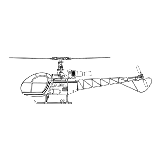
主要諸元
Main features
ギヤ比
Gear ratio
/ 9.625 : 1 : 5.5
無線機
Radio control device
/ ヘリ用プロポセット (別売)
Programmable transmitter set for model
helicopters (Sold separately)
適合エンジン
Compatible engine
/ 30∼46クラス (別売)
30-46 class engine (Sold separately)
※46クラスエンジンの搭載には別途購入品が必要です。
(ご注意:50クラスエンジンの搭載はできません)
※Additional parts must be purchased in order to mount
46 class engines. (Note that the 50 class engines
can not be mounted.)
262mm
404mm
MADE IN JAPAN
1190mm
2003
C
No.104471
Advertisement
Table of Contents

Related Manuals for Hirobo Lama SA-315B


Summary of Contents for Hirobo Lama SA-315B
- Page 1 主要諸元 Main features 組立前に必ずこの説明書を最後まで、よくお読みにな ギヤ比 Gear ratio / 9.625 : 1 : 5.5 り、正しくお使い下さい。特に、「安全のために必ず 無線機 Radio control device / ヘリ用プロポセット (別売) お守り下さい」は、飛行前に必ず読んで下さい。 Programmable transmitter set for model helicopters (Sold separately) この説明書は、大切にお手元に保管して下さい。 適合エンジン Compatible engine / 30∼46クラス (別売) 30-46 class engine (Sold separately) 製品改良のため、予告なく仕様を変更する場合があります。...
-
Page 2: Table Of Contents
組立を始める前に安全のために必ず For safety reasons, observe the following お守り下さい。 precautions before assembly. Thank you very much for purchasing a Hirobo product. In order to be このたびは、ヒロボー製品をお買上げいただき、ありがとうござい able to use this product safely, please read this manual before flying the ます。 安全にお使いいただくために、飛行前にこの取扱説明書を最後まで... - Page 3 (オイル / グリス)、送・受信機用バッテリーが充分に充電されて or at the engineering services section of Hirobo’s Sales Department. いるかを点検してください。 Before starting the engine, make sure that there are no loose screws, that all 8.
- Page 4 警告 WARNING 燃料について FUEL 1. 模型用エンジンは模型専用のグロー燃料が必要です。 1. Only use GLOW fuel for model engines. ◆ ガソリンや灯油は使用できません。 Gasoline or kerosene may cannot be used. ◆ グロー燃料は揮発性が高く引火しやすいので取り扱いには十分注 GLOW fuel is highly volatile and flammable. Handle with care. 意してください。 Use properly in accordance with the type of engine. (ABC or ring fitted) ◆...
- Page 5 Store in a dry place out of the reach of children. い。 3. Inquire about repairs at the store from where you purchased the product or 3. 修理は、お買上げの販売店、またはヒロボー(株)営業本部エンジニ at the engineering services section of Hirobo’s Sales Department. アリングサービスにお申し付けください。 Individuals lacking proper knowledge or tools necessary for repairs may ◆ 修理の知識のない方や専用工具を持っていない方が修理をする...
- Page 6 無線操縦ヘリコプターを安全に For safe handling of the radio controlled helicopter お取り扱いいただくために 先に、 無線操縦エンジン模型として共通の注意事項を述べましたが、 ヘ In addition to the standard precautions previously mentioned regarding radio リコプターの場合、さらに次に述べる注意事項を守ってください。 controlled engines, please observe also the following precautionary items which are specific to helicopters. 警告 WARNING 実機の場合、飛行前には厳しい点検が義務付けられています。無線操...
- Page 7 警告 WARNING フライト中の安全確認 In-flight safety check 1. エンジンを始動するときは周辺に当たるものや、 巻き込まれそうな Check that there are no objects in the surrounding area that may get ものがないか確認してください。 entangled or struck by the unit. 2. 周囲に同じ周波数の使用者がいないことを確認して、 送信機→受信 Check that there are no other operators in the surrounding area using the 機の順番にスイッチを入れ、...
- Page 8 小物部品の名前、原寸図、使用数 Part name, full-scale illustration, and quantity. 警告 WARNING Due to a lack of proper testing, please acknowledge that Hirobo 本製品の改造、又、弊社以外の部品交換について、十分なテストを will not take responsibility for accidents resulting from 行っていませんので、事故発生の可能性もあります。その場合、一 remodeling the unit or from the replacement of parts with those 切の責任を負いかねますのでご了承ください。...
- Page 9 How to read part types and sizes ネジの種類とサイズの見方 本説明書の文中に記載している記号は、次の約束になっています。 The symbols shown in this instruction manual are shown as below: ● 単位はミリメートルです。以下、文中で長さなどに表示されてい The unit of measurement is the millimeter. The lengths, etc. shown る単位はミリメートルです。 in the following are indicated in millimeters. ナベ頭ビス...
- Page 10 ジャイロ Gyro 2513-040 ¥2,800 エンジンスターター用 エンジンプラグ グロープラグコード ヒロボー RC 燃料 バッテリー 12V ヒート用バッテリー Booster cables HIROBO RC Fuel For Helicopter & Airplane Engine plug heating 12V engine starter battery battery 15% ニトロメタン(オイル約 20%) 15%Nitromethan (approx.20%oil) 2513-066 2515-200 ¥4,000 2401-004 ¥1,000 ¥1,400...
- Page 11 あると便利な周辺用具 Useful tools フライホイールレンチ ブレードサポート RC メカクッションパッド 燃料フィルター プラグレンチ 2513-025 Fly wheel wrench Blade support RC mechanical cushion pad Fuel filter Plug wrench ¥2,500 2513-026 ¥1,000 2513-052 ( ピンク /Pink) ¥500 2513-035 ¥980 2513-039 ¥500 2513-062 ( キイロ /Yellow) ¥500 2513-038 ¥300 バッテリーチェッカー...
-
Page 12: Clutch Bell Assembly
2. 組立編 Assembly エレベーターレバー・エルロンレバーの組立 Elevator, aileron lever assembly M2ロッドエンド M2X8PH ....... 4 M2X10CS M2 rod end LMエレベーターレバー LM elevator lever M2X10CS ......3 LMエレベーターシャフト LMエレベーターロッド LM elevator shaft ø5ボール ......4 LM elevator rod ø5 ball ø3X4.5X0.5FW ....4 Brg. ø5X8X2.5 ø4Eリング... -
Page 13: Fuel Tank Assembly
燃料タンクの組立 Fuel tank assembly ø2.5X5のシリコンパイプは図を参考に切って、 使 燃料タンク 用してください。 Fuel tank Cut the ø2.5X5 silicon pipe as shown in this figure. FWø5Xø10X1 ...... 1 シリコンパイプø2.5X5X180 Silicon pipe ø2.5X5X180 FWø5Xø12X0.8 ....1 燃料タンクニップル Fuel tank nipple 燃料タンクオモリ 燃料タンクキャップ Fuel tank sinker Fuel tank cap M5ナット... - Page 14 M3X3SS ジョイント軸カバー M3X3SS ....... 2 Joint shaft cover カウンタージョイント軸 Counter joint shaft カウンタージョイント軸を矢印の方 向へ一杯押しつけ、ガタを無くした 状態でジョイント軸カバーを通し、 Brg. に接触する位置に合わせます。 Push the counter joint shaft as far as it will go in the direction of the arrow, pass スキ間 it through the joint shaft cover and ensure that there is no play, and locate the cover 0.3mm M3X3SSの取付状態...
- Page 15 サーボフレームの組立 Servo frame assembly M3X12皿TS ....... 16 M3x12countersunk TS M3X12皿TS M3X12 countersunk TS M3X12皿TS M3X12 countersunk TS M3X12皿TS M3X12 countersunk TS M3X12皿TS M3X12 countersunk TS...
- Page 16 エンジンの組立 Engine assembly M3X12CS ......4 M3X8CS M3X8CS ....... 2 M3X6皿ネジ ......4 クラッチシュー M3X6 countersunk screw Clutch shoe ドライブナット (エンジン付属) FWø6Xø13X1 ...... 1 Drive nut (included with engine) M2X12PH ......1 FW ø6Xø13X1T ø5ボール ......1 フライホイール30クラスエンジン用 Flywheel for 30 class engine ø5 ball M2ナット...
-
Page 17: Engine Installation
エンジンの取付 Engine installation M3X28CS ......2 M3X14CS ......4 M3X12皿TS ......8 M3X12 countersunk TS FWø3X9X1 FWø3X9X1 ......4 M3X14CS 注 意 Caution エンジンを上に押し付けた状態から約 1mm 下げて固定します。 Set the engine approximately 1mm lower than the fully raised position. 注 意 Caution クラッチベルの軸とエンジンのシャフトが一直線となるよう... -
Page 18: Landing Gear Installation
ランディングギヤの組立 Landing gear installation M3X20TS ......4 M3X5SS ....... 4 M3X16TS ......2 M3X20TS タイヤ Tire クロ M3X5SS Black M3X16TS M3X20TS ダークグレー Dark gray M3X5SS メインギヤの取付 Main gear installation 注 意 Caution メインマスト M3X3SS Main mast しっかりと締付けてください。 M3X16CS ......1 Tightly fasten. - Page 19 ウォッシュアウト部の組立 Wash-out assembly ø3X4.5X0.5FW Brg. ø3X6X2.5F M2X8PH ....... 2 ø3X4.5X0.5FW Brg. ø3X6X2.5F M2X8PH ø5ボール ......2 ø5 ball ø5ボール M3X10PH ø5 ball コントロールアーム M3X10PH ......2 Control arm ø2X11.8ニードルピン ラジアスアーム ø2X11.8 needle pin Radius arm ニードルピン ø2X11.8 ..2 注 意 Caution Needle pin ø2X11.8 ウォッシュアウトコントロール...
- Page 20 ヨーク / ブレードホルダー部の組立 Yoke and blade holder assembly ヨーク FW ø4Xø9X0.8 ....2 Yoke M3X8CS M4ナイロンナット ..... 2 M4 nylon nut 注 意 Caution Cø5Xø8X5.5 ......2 センターハブ Center hub M3X8CS ....... 2 ダンパーゴムがヨークから 出っ張らないように少量のオ イルをつけて、しっかりと押 し込みます。 Apply a small amount of oil to the damper rubber and insert it completely into the yoke.
-
Page 21: Swashplate Assembly
スタビライザー部の組立 Stabilizer assembly A=B=132mm ø5ボール ......2 ø5 ball M4X4SS M2X8PH ....... 2 M4X4SS ....... 2 M3ナット ......2 M3 nut カバーフィルム Cover film M4X4SS M3ナット 注 意 Caution M3 nut スタビライザーブレードとスタ ビライザーコントロールアーム は平行であること。 The stabilizer blade and the スタビストッパー stabilizer control arm must be Stabilizer stopper parallel. - Page 22 ロータヘッド部 / ウォッシュアウト部 / スワッシュプレート部の取付 Rotor head, wash-out and swash plate installation M3 ナイロンナット 12mm M3 nylon nut M3X18CS ......1 センターハブ 90° Center hub M3X14皿TS M3X14 countersunk TS M3ナイロンナット ..... 1 M3 nylon nut マスト穴 M3X18CS Mast hole ラジアスブロック Radius block M3X14皿TS ......
- Page 23 テールユニットの組立 テールギヤケース(R) Tail gear case (R) Tail unit assembly テールピッチプレート Assy(組立済) M2X20CS ......1 Tail pitch plate assembly (Pre-assembled) 組立済 Pre-assembled Brg. ø5X11X5ZZ 3X8X11カラー M3X16CS ......2 ø5X7X0.2FW 3X8X11 collar テール第二軸 ø1.5 Eリング テールピッチレバー ø1.5 E ring Tail 2nd shaft M2X10TS-2 ......
- Page 24 テールブームトラスの組立 Tail boom truss assembly 1. Combine the tail boom truss lower part and boom trusses 1. テールブームトラス下部とブームトラス R, L を取 り付け、M2X15PH と M2 ナット 8 本で締め込みま R and L. Then, tighten them with eight M2X15PH and す。このときネジ止めにネジロックまたは瞬間接 M2 nuts. M2X10TS-2 ......
- Page 25 テールトラス・リヤフレームの組立 Tail truss and rear frame assembly リヤフレームR M3X10TS-1 ......2 M3X10TS-1 トラスAssy Rear frame R Truss assembly ø3X8X0.5FW M3X12TS-2 ......9 クロスメンバーB Cross member B M3X8PH ....... 2 M3X3SS ....... 3 FWø3X8X0.5 ....... 2 フレームAssy リヤフレームL Frame assembly Rear frame L M3X12TS-2 M3X12TS-2 M3X3SS...
-
Page 26: Servo Installation
注 意 Caution M4X4SS はネジロック剤を付け、しっかりと締め付けて下さ い。 飛行中にゆるんだ場合、 テールのコントロールがきかなく なり大変危険です。 Apply thread-locking agent to the M4X4SS and firmly tighten ø2ジョイント them. If they become loose during flight, you may lose ø2 joint control of the tail which is a very dangerous. テールドライブシャフトの取付はまず最初に下図の位置を決め... - Page 27 受信機・ジャイロの取付 Receiver and gyro installation ニードル用穴 Hole for needle 注 意 Caution 受信機バッテリー等はラバーフォームなどに包 み込み、バンドを掛けて搭載してください。 Load the receiver battery after wrapping it in rubber foam and fastening with a band. 注 意 Caution テープを貼り付ける前に、貼り付ける部分の汚 れ等を十分に拭き取ってください。 Before applying tape, make sure the surface is wiped clean of dirt.
- Page 28 サーボの動作確認 Servo movement check 注 意 Caution 注 意 Caution 回転方向が逆の場合は、送信機のリバースス 作業に入る前に送信機用のバッテリーの充電を イッチを切り替えて、指定の通り動くように 行ってください。 セットしてください。 Before starting, recharge the transmitter If the rotational direction is reversed, change battery. the transmitter’s reverse switch and set it to move as indicated. モード I スロットル&ピッチ...
- Page 29 ローターヘッド部のリンケージ Rotor head linkage ピッチロッド スタビライザーコントロールロッド Pitch rod Stabilizer control rod ロッドエンド ...... 8 Rod end ミキシングアームロッド ロッドエンドM2X12.5 ..4 Mixing arm rod Rod end M2X12.5 ピッチロッド スタビライザーコントロールロッド Pitch rod Stabilizer control rod ダブルリンク Double link ミキシングアームロッド Mixing arm rod ダブルリンク...
-
Page 30: Aileron Linkage
エルロンのリンケージ Aileron linkage エルロンロッド(2 セット) Aileron rod (2 sets) ロッドエンド ...... 4 90mm Rod end 約81mm M2X10PH ......2 Approx. 81mm M2ナット ......4 M2X10PH M2 nut 約13mm ø5ボール ......2 Approx. 13mm φ5ボール ø5 ball 90° ø5 ball M2ナット M2 nut 不要な部分は... - Page 31 エレベーターのリンケージ Elevator linkage エレベーターロッド Elevator rod 83mm ロッドエンド ...... 1 Rod end 約76.5mm Approx.76.5mm モード I モード II Mode I Mode II 不要な部分はカットする Cut out any unnecessary parts. 送信機のエレベータスティックとトリ ムがニュートラルにあることを確認し てください。 Check that the transmitter’s elevator stick and trim are in neutral. エレベーターロッド...
- Page 32 コレクティブピッチのリンケージ コレクトピッチロッド Collective pitch linkage Collective pitch rod 77mm 約70.5mm Approx.70.5mm ロッドエンド ...... 1 Rod end モードI モードII Mode I Mode II 送信機のスロットルスティックとトリム がニュートラルにあることを確認してく ださい。 Check that the transmitter’s throttle stick and trim are in neutral. コレクトピッチロッド 不要な部分はカットする。 Collective pitch rod Cut out any unnecessary parts.
-
Page 33: Throttle Linkage
スロットルのリンケージ Throttle linkage スロットルロッド 83mm Throttle rod 約80mm Approx. 80mm スロットルレバーにスロットルロッドを取り付け、 キャブレターを全閉にに したとき、 スロットルロッドがクーリングファンカバーに接触しないように、 M5 ナットをゆるめて調整してください。 (調整後は、M5 ナットをしっかり と締めてください。 ) モード I モード II Install the throttle rod to the throttle lever and, by loosening the M5 nuts, Mode I Mode II check that the throttle rod does not come into contact with the cooling fan 送信機のスロットルスティックとトリム... - Page 34 ラダーのリンケージ Rudder linkage ø1.8ピンバイスで穴を開ける。 Make holes with the ø1.8 pin vise. モードI モードII Mode I Mode II 送信機のエレベータとスロットルのスティッ クとトリムがニュートラルにあることを確認 してください。 Check that the stick and trim of the transmitter’s elevator and throttle are in neutral. ロッドは、サーボホーン下面より差し込みます。 Insert the rod from the bottom of the servo horn. 90°...
- Page 35 各舵の動作確認 Rudder movement check 確認する場所 モード I Mode II Check points スワッシュプレートを機 体後方から見たとき。 When viewing the swash plate from the rear of the unit. 機首方向 スワッシュプレートを機 Nose direction 体側面から見たとき。 左図と動きが一致しない When viewing the swash ときは、サーボの回転方 plate from the side of the 向が逆になっています。...
- Page 36 ピッチの測り方 Pitch measurement メインブレード Main blade 1. メインブレードの先端から約 80mm のところ スタビライザー にピッチゲージを取付け、機体の前方に向け Stabilizer てください。 Install the pitch gage at about 80mm from the tip of the main blade and point it towards the front of the unit. 2. 送信機のスロットルスティックを動かし、スタビライ ザーバーとピッチゲージを平行にし、 指された目盛りを 読んでください。...
- Page 37 Low pitch ※ 1 別頁 送信機別データシートを参照してください。 See attachment for transmitter data. 注 意 Caution 必ずヒロボー製ピッチゲージ (2513-040) を使用してください。 Make sure to use only Hirobo manufactured pitch gages (2513-040). 少し持ち上げて測ります。 ピッチゲージをメインブレードの先端から約 80mm にとりつけ、スタビライ Lift slightly and measure. ザーバーを水平にしてピッチゲージで測ります。 (メインブレードを少し持ち上げて測ります。 ) Install the pitch gage at approx. 80 mm from the end of the main blade having the stabilizer bar horizontal and measure with the pitch gage.
- Page 38 サイドカバーの取付 Side cover installation M3X8PH ....... 2 M3X12TS-2 ......4 M3X8TS ....... 2 サイドカバーR Side cover R M3X8PH M3X8PH M3X8TS 白 White 黒 Black オイルタンク Oil tank サイドカバーL Side cover L M3X12TS-2 配管図 Piping diagram ジョイントパイプ キャブレターニップルへ Joint pipe To the carburetor nipple マフラーニップルへ...
- Page 39 ダミーブレースの組立 Dummy brace assembly ダミーブレース前 Dummy brace (Front) M3X8TS ダミーブレース後 M2X12PH ......4 Dummy brace (Rear) M3X8TS M3X8TS ....... 6 ダ ミ ーブレース後 Dummy brace (Rear) M3X8PH ....... 2 ダミーダンパー Dummy damper M3X8PH M3ナ ッ ト M3ナット ......2 M3 nut M3 nut M2X12PH ダミーブレース前...
- Page 40 コクピットの組立 Cockpit assembly ダークグレー Dark gray ダークグレー LMメーターデカール Dark gray LM meter decal メーターパネル Meter panel 白紙 計器盤 White paper Instrument panel メーターパネルの形に合わせ、はみ 瞬間接着剤 Instant adhesive 出さない様にカットします。後ろに 白い紙を貼り付けます。 Align it with the meter panel and cut so that there are no protruding parts. Affix a piece of white paper to the back.
- Page 41 キャビンの組立 Cabin assebmly 赤 白 White キャノピー Windshield M2.6X12TS M2.6X6トラスTS M2.6X6 truss TS ドアー取手 Door knob M3X8TS M2.6X12TS 両面テープ Double-sided adhesive tape センターマーク M2.6X6トラスTS Center mark M2.6X6 truss TS M2.6X12TS ......2 M2.6X6トラスTS ....10 M2.6X6 truss TS センターマークをここに合わす M3X6TS Align the center mark here.
- Page 42 デカールの貼付け、塗装について Affixing the decals and painting キャビン、サイドカバー、リヤカバー、テールトラス、ダミーブレー Those who would like to paint the cabin, side cover, rear cover, tail truss, dummy ス、スキッドをオリジナルのカラーで塗装をされたい場合は、ウレタ brace and skid in the original color should use a urethane paint. However, due ン塗料をご使用下さい。ただし、材料の性質上、時間の経過とともに to the properties of the material, the paint may begin to peel with time. はがれる場合があります。...
- Page 43 完成チェック Checking final assembly ① サーボの取付方向は間違っていませんか? ① Check that the servos mounted in the correct directions. ② Check that each rudder moves in accordance with the stick operation. (Check ② スティックの操作通り各舵は動いていますか? the servo rotation direction and connection of each rod.) (サーボの回転方向と各ロッドとの接続を確認して下さい。...
-
Page 44: Flight
3. フライト編 Flight ヘリコプターは、メインローター、テールローターが高速で回転しま The helicopter’s main and tail rotors spin at very high speeds. Make sure to す。 follow these instructions for a safe and enjoyable flight. 飛行には次の事に十分注意し、安全なフライトをお楽しみ下さい。 機体の運搬 Transporting the unit 飛行場までの機体の運搬で、車内で機体が倒れたりすることのないよ When transporting the unit to an airfield, secure it in a way so as to prevent it from falling over. - Page 45 出かける前に Before leaving for the airfield ☆ まずは、イメージフライト Do an imaginary flight first. ● ここでは操縦の基本となる各舵の動きを指先に覚え込ませます。 自 Familiarize your fingers with the movement of the rudders. This 然に指が動くようになるまで反復練習!! is the basics for maneuvering the unit. Practice repeatedly until your fingers move naturally. 1.
- Page 46 フライトに出かけよう Let’s go to the airfield! 注意 Caution ☆ もう一度チェック → ネジは確実に締まっていますか? Check again Are the screws firmly tightened? ☆ プロポ及び受信機用のニッカドバッテリーは充分に充電されてい Are the transmitter and receiver batteries fully charged? ますか? 飛行場に着いたら When arriving at the airfield 動作確認 Check the movement 送信機の電源スイッチを...
- Page 47 エンジン始動と停止 Starting and stopping the engine 注意 Caution モード I Mode II 周囲に同じバンドを使っている人がいない事を確認して送信機、 受信機の順にスイッチを入れます。Only turn on y トリム: ハイ Trim: high First, check that there are no other operators in the surrounding area using the same frequency and then turn on the transmitter followed by the receiver.
- Page 48 トラッキング調整 Adjusting the tracking 注意 Caution トラッキングの調整は危険ですので、 機体から10m程離れて行ない Since adjusting the tracking is dangerous, do so at a distance ます。 of at least 10m away from the unit. Slowly raise the throttle stick to its high position and stop just before 1.
- Page 49 ホバリングの練習 Hovering practice 注意 Caution 周囲に人のいないことを確認して下さい。 Make sure that there are no people or obstructions in the 周囲に障害物がないことを確認して下さい。 vicinity. In order to fly the unit safely, you must first practice hovering ☆ 初めにヘリコプターを安全に飛行させるために、 操作の基本となる extensively. This constitutes the basis of flight operation. (“Hovering” ホバリングを確実に行えるよう十分に練習して下さい。...
- Page 50 エルロン・エレベーター操作の練習 Step. 2 Aileron and elevator operation practice 注意 Caution 1. スロットルスティックをゆっくりと上げます。 機首が動いてしまったときは、必ずスロットルスティックを下 2. 機体が前後左右に動いたら、 動いた方向と逆に げ、 着地させ、 立ち位置を機体の斜め後方に移動して練習を再開 エルロン、 エレベータースティックを少しずつ しましょう。また、機体が遠くに離れてしまった時も一旦、 機体 動かし、元の位置にもどるようにしましょう。 を着地させ、 機体から10mぐらいのところに近づき、 練習を再開 しましょう。 1. Slowly raise the throttle stick. If the nose of the unit moves, lower the throttle stick 2.
- Page 51 各トリムの調整 Adjustment of each trim Slowly raise the throttle stick and just as the unit lifts off the ground, you may スロットルスティックをゆっくりと上げていき、機体が浮き上がろう notice the unit leaning in different directions. Use the trims to correct this. とする時、機体はいろんな方向へ傾きます。これを修正するのがトリ ムです。 Mode II モード I 1.
-
Page 52: Cleaning And Storage
The tail sways left and right during flight at full speed. Should you still have some doubts even after having tried the above, 以上のことをお調べになって、それでも不具合があるときは使用を stop using the unit and consult your dealer or Hirobo’s Engineering 中止し、お買上げの販売店または、当社エンジニアリングサービス にご相談下さい。 Service Section. 清掃・保管方法... - Page 53 エンジン始動からホバリングまでがスムーズでない場合は、次の項目をチェックしてください。 Should the unit not operate smoothly from engine start-up to hovering, check the following items. エンジンは始動しますか? Does the engine start? 基本的なチェック Basic items to be checked 連続で回転しますか? 1. 始動用電池はありますか?また、 ブースターコードが接触不良になっていないかチェック Does the engine run continuously? 2. スターター用バッテリーは、充電されているかチェック 3. スターターの回転方向が正しいかチェック 4.
-
Page 54: Maintenance
4. メンテナンス編 Maintenance 墜落 ・ 横転した場合 In the case of a fall or crash 必ずメインローターを交換してください Always replace the main rotor. チェック! 各部の点検 部品にキズ、破損がある Check each section. Check! Parts are scratched or broken. チェックポイント Check point ・スタビライザーバーの曲がり ・テールブームの曲がり、へこみ 部品交換 ・ラダーコントロールロッドの曲がり Replace the parts. - Bent stabilizer bar - Bent or dented tail boom pipe - Bent rudder control rod... - Page 55 I. メインマストの交換 I. Main mast replacement Apply thread locking agent to the screws indicated with Lock Lock マークが付いているネジは、 ネジロック剤をつけてくださ when assembling. い。 1. ローターヘッド部とウォッシュアウ ト部をつなぐリンケージロッドを取 2. ローターヘッドAssy の M3X18CS を取 外します。 M3ナイロンナット 外します。 1. Remove the linkage rod between the M3 nylon nut 2.
- Page 56 III. スピンドルの交換 III. Spindle replacement 2. ブレードホルダーのM4ナイロンナットを取外します。 3. ブレードホルダーをはずし、 スピンドルを引き抜きます。 2. Remove the blade holder M4 nylon nuts. 3. Remove the blade holders and pull out the spindle. M4ナイロンナット M4 nylon nut FW ø4X9X0.8T ピッチロッド Pitch rod スピンドル Spindle FW ø4X9X0.8T ピッチロッド...
-
Page 57: Repair Parts
日祝日配達 希望する ・ 希望しない フリガナ 指定時間 無 ・ 有( 時頃) お名前 〒 都・道 市・郡 ご住所 府・県 区 F A X ( ) ( ) T E L 品 名 コードNo. 単 価 数 量 金 額 ①パーツ代金の合計 (パーツ係) ②消費税(5%) 広島県府中市府川町138 〒726-0004 ③送料/代引送料(代引手数料込) TEL:(0847 )40-0088 (代) FAX:45-7670 お支払金額(①+②+③) http://model.hirobo.co.jp/... - Page 58 パーツリスト Parts list 2532-047 0402-202 2532-002 2532-029 0402-006 2525-009 2521-103 0402-640 2500-068 0402-641 2532-002 0402-505 0402-503 0402-545 2532-038 2505-006 2505-007 2536-001 0402-502 2505-007 オプシ ョ ン Optional 2500-082 オプシ ョ ン Optional 0402-272 0402-545 0402-208 0402-508 2505-002 2531-003 0402-055 2506-019 2500-057 0402-506 2533-005...
- Page 59 コードNo. 品名 入数 価格(円) 備考 Code No. Particulars Q'ty Price (Yen) Remarks ダンパーゴム 0402-006 Damper rubber スタビライザーバー 0402-055 Stabilizer bar ZSヨーク 0402-202 ZS yoke スタビライザーブレード ナット,スタビブレードフィルム付 0402-208 1,200 Stabilizer blade Nuts and stabilizer blade film attached スタビブレードフィルム 0402-272 Stabilizer blade film スラストワッシャー...
- Page 60 オプシ ョ ン Optional 0402-319 オプシ ョ ン Optional 0402-574 2508-003 2533-012 0402-207 0402-014 0402-591 2500-080 0402-254 2508-003 2500-061 2531-003 2500-048 2500-048 0402-016 0402-327 0402-318 0402-016 0402-326 0400-004 0402-310 2500-081 0402-321 2532-002 0402-324 0402-642 0402-324 0412-121 ( 30用) オプシ ョ ン Optional 0412-122 (...
- Page 61 コードNo. 品名 入数 価格(円) 備考 Code No. Particulars Q'ty Price (Yen) Remarks 金属製クラッチベルライニング 0400-004 Metal clutch bell lining マストロック ø8 0402-014 Mast lock ø8 オートロクラッチセット 1 式 0402-016 3,000 Auto-rotation clutch set 1 set 32 用エンジンマウント ネジ、FW付 0402-023 1,400 Engine mount for 32 engine With screws and FWs マフラーセット...
- Page 62 2506-019 0402-107 2500-057 2506-032 2532-029 2500-056 0402-524 2500-054 0402-107 2507-002 2525-009 0402-107 2500-054 0402-306 2524-001 2506-019 2500-057 0402-524 2538-003 2533-012 2533-016 2506-010 2533-005 2505-001 2525-009 0402-308 0402-307 0402-606 (オプション3枚ローターヘッド) (Optional three-blade rotor head) 0402-612 2524-014 2505-007 2506-007 2532-010 2500-068 0402-801 0402-512 0402-006 2532-003...
- Page 63 コードNo. 品名 入数 価格(円) 備考 Code No. Particulars Q'ty Price (Yen) Remarks ダンパーゴム 0402-006 Damper rubber 1 式 Wリンクセット 0402-025 W-link set 1 set NS エルロンレバーセット 1 式 0402-107 NS aileron lever set 1 set メインマスト MRB-III R/H 0402-131 Main mast MRB-III R/H S-30 エレベーターレバーセット...
- Page 64 0402-528 0402-529 2524-003 2524-004 ( 赤) (Red) 0402-351 ( 白) (White) 0402-337 0402-216 0402-205 0402-217 0402-314 2500-003 0402-312 0402-313 2526-003 2500-003 2500-003 0404-336 2523-009 0402-347 ( 赤) (Red) 0402-371 ( 白) (White) 0402-059 0402-331 2505-006 0402-354 ( 赤) (Red) 0402-376 ( 白) (White) 2532-006 2531-002 0402-346 (...
- Page 65 コードNo. 品名 入数 価格(円) 備考 Code No. Particulars Q'ty Price (Yen) Remarks ラダーコントロールシャフトセット 1 式 0402-059 Rudder control shaft set 1 set ZS テールピッチプレートセット 1 式 0402-205 1,600 ZS tail pitch plate set 1 set テールハウジング Assy 1 式 0402-216 2,500 Tail housing assembly 1 set...
- Page 66 0402-349 ( 赤) (Red) 0402-311 ( 白) (White) 0402-373 ( 赤) (Red) 0402-348 0402-355 0402-372 ( 白) (White) 0402-345 0402-350 ( 赤) (Red) ( 白) (White) 0402-374 0402-355 ( 赤) (Red) ( 白) (White) 0402-375 0402-335 0402-353 0402-342 0402-377 0402-352 ( イエローラ イ ン) (Yellow line) 0402-339 (...
- Page 67 コードNo. 品名 入数 価格(円) 備考 Code No. Particulars Q'ty Price (Yen) Remarks S-30 フレームクロスメンバー 1 式 0402-311 1,200 S-30 frame cross member 1 set LM ダミーエンジンセット 1 式 0402-335 LM dummy engine set 1 set LM デカール(ブルーライン) 0402-339 1,800 LM decal (blue line) LM コックピット偽装品...
- Page 68 FUTABA FF9-H 1ch(AIL) 2ch(ELE) 3ch(THR) 4ch(RUD) 5ch(GYR) 6ch(PIT) (R/U) 100% 140% 100% 100% 100% 100% E.POINT (L/D) 100% 140% 100% 100% 100% 100% 100% 100% AIL:D ----- ----- ----- ELE:A 100% ----- ----- ----- Cond (NORM) (F/S) REVERS NORM NORM NORM NORM POS1...
- Page 69 JR X-3810 ELEV RUDD DUAL- RATE ・ 100% 100% NORM ST-1 A.D.T ST-2 HOLD THRO ELEV RUDD GEAR REVERSE SW NORM NORM NORM 100% 100% 100% 110% (H/L/D) TRAVEL ADJUST 100% 100% 100% 110% (L/R/U) FAIL SAFE (SPCM) F.S. HOLD HOLD HOLD HOLD...
- Page 70 SANWA RD-6000 Super SWASH TYPE NORMAL (1) EL (2) AI (3) TH (4) RU (5) G (6) P -28% -14% 3(HOLD) 100% 100% 100% 100% 100% 100% 100% 3(HOLD) 100% 3(HOLD) -100% (UP/LT) 150% 115% 130% 100% 150% -80% (DW/RT) 150% 115% 100%...
- Page 72 広島県府中市府川町 〒 HIROSHIMA-PREF., JAPAN. 〒726-0004 TEL: 0847 40-0088 FAX:45-7670 ( ) (代) TEL:0847-40-0088 FAX:0847-45-7670 http://model.hirobo.co.jp/ http//model.hirobo.co.jp/ 注意 Note ①本書の内容の一部または全部を無断で転載することは禁止されています。 ②本書の内容については、将来予告なしに変更することがあります。 ③本書の内容について万全を期しておりますが、万一ご不審な点や誤り、記載もれなどお気付 きのことがありましたら、ご一報くださいますようお願いいたします。 ④運用した結果については③項にかかわらず責任を負いかねますので、ご了承ください。 ①Reproduction of this manual, or any part thereof is strictly prohibited. ②The contents of this manual are subject to change without prior notice.
Need help?
Do you have a question about the Lama SA-315B and is the answer not in the manual?
Questions and answers