Table of Contents
Advertisement
組立前に必ずこの説明書を最後まで、よくお読みにな
り、正しくお使い下さい。特に、「
に必ずお読み下さい」は、組立前及び飛行前に必ず読
んで下さい。
この説明書は、大切にお手元に保管して下さい。
製品改良のため、 予告な く仕様を変更する場合があ り ます。
Before assembly, completely read this instruction
manual. In particular, read the "1. Read before
assembly" section before assembly and operating the
unit.
Keep this instruction manual in a handy, safe place.
In order to make improvements to this product, the
specifications is subject to change without prior notice.
主要諸元
全備重量
1.
組立を始める前
ギヤ比
無線機
適合モーター
適合バッテリー
適合スピード
コントローラー
Main features
Overall weight
Gear ratio
Radio control device
Compatible motor
Compatible battery
Compatible speed
controller
144mm
/
1,600g
4
:14.8V3200Ah
約
(
セル
使用時)
/ 3.92:1:4
4
3.61:1:4
3
(
セル)
(
セル)
/
ヘリ用プロポセ ッ ト (PCM方式推奨) 小型サーボ
/ LEX
37/10T/890
アウターローターモーター
KV890
45A/60S
(
最大電流
)
/ LEX
14.8V 3200mAh
リポバッテ リ ー
3200mAh4
(リ チウムポ リ マーバッテ リ ー
/ LEX ESC60A BEC
3
4
60A BEC
(
セル∼
セル対応 最大
付)
/ Approximately 1,600 g (When using 4 cells: 14.8 V 3200 Ah)
/ 3.92:1:4 (4 cells) 3.61:1:4 (3 cells)
/ Programmable transmitter set for model helicopters
(Pulse Code Modulation (PCM) is recommended.) ,
four small servos and one gyro (Sold separately)
/ LEX outer rotor motor 37/10T/890
(KV 890 maximum current 45 A/60 sec.)
/ LEX Lithium polymer battery 14.8 V 3200 mAh
(Lithium polymer battery 3200 mAh, 4 or 3 cells)
/ LEX ESC60A BEC
(3 cells to 4 cells compatible, maximum current 60 A, with BEC)
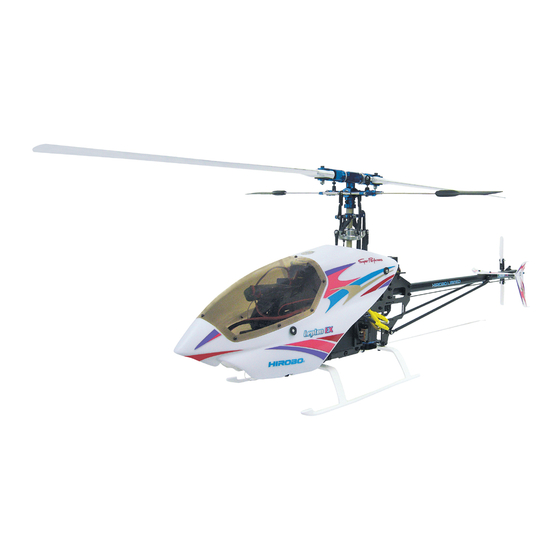
955mm
281mm
937mm
MADE IN JAPAN
EX
レプトン
4
+1
個
ジ ャ イ ロ (別売)
3
セルまたは
セル)
160mm
2006
C
No.10B10
Advertisement
Table of Contents

Related Manuals for Hirobo Lepton EX


Summary of Contents for Hirobo Lepton EX
- Page 1 レプトン 主要諸元 組立前に必ずこの説明書を最後まで、よくお読みにな 1,600g :14.8V3200Ah 全備重量 約 ( セル 使用時) / 3.92:1:4 3.61:1:4 り、正しくお使い下さい。特に、「 組立を始める前 ギヤ比 ( セル) ( セル) 無線機 ヘリ用プロポセ ッ ト (PCM方式推奨) 小型サーボ 個 ジ ャ イ ロ (別売) / LEX 37/10T/890 に必ずお読み下さい」は、組立前及び飛行前に必ず読 適合モーター アウターローターモーター KV890 45A/60S (...
-
Page 2: Table Of Contents
For safety reasons, observe the following 組立を始める前に安全のために必ず precautions before assembly. お守り下さい。 Thank you very much for purchasing a Hirobo product. In order to be このたびは、ヒロボー製品をお買上げいただき、ありがとうござい able to use this product safely, please read this manual before flying the ます。 helicopter. Please fly the helicopter safely observing all rules and 安全にお使いいただくために、飛行前にこの取扱説明書を最後まで... - Page 3 (オイル / グリス)、送・受信機用バッテリーが充分に充電されて or at the engineering services section of Hirobo’s Sales Department. いるかを点検してください。 Before starting the engine, make sure that there are no loose screws, that all 8.
- Page 4 Store in a dry place out of the reach of children. 3. 修理は、お買上げの販売店、またはヒロボー(株)営業本部エンジニ 3. Inquire about repairs at the store from where you purchased the product or アリングサービスにお申し付けください。 at the engineering services section of Hirobo’s Sales Department. ◆ 修理の知識のない方や専用工具を持っていない方が修理をすると、 Individuals lacking proper knowledge or tools necessary for repairs may 十分な性能を発揮しないだけでなく、事故や怪我の原因となり...
- Page 5 無線操縦ヘリコプターを安全に For safe handling of the radio controlled helicopter お取扱いいただくために In addition to the standard precautions previously mentioned regarding radio 先に、無線操縦模型として共通の注意事項を述べましたが、ヘリコプ controlled models, please observe also the following precautionary items which ターの場合、さらに次に述べる注意事項を守ってください。 are specific to helicopters. WARNING 警告 For real aircraft, strict pre-flight inspections are mandatory. The radio 実機の場合、飛行前には厳しい点検が義務付けられています。無線操...
- Page 6 警告 WARNING フライト中の安全確認 In-flight safety check 1. Check that there are no objects in the surrounding area that may get 1. 飛行するときは周辺に当たるものや、巻き込まれそうなものがな entangled or struck by the unit during flight. いか確認してください。 2. Check that there are no other operators in the surrounding area using the 2. 周囲に同じ周波数の使用者がいないことを確認して、送信機のス...
- Page 7 For the safe operation of electric models 電動模型の安全について WARNING 警告 Before using the unit ご使用の前に Never leave equipment such as the transmitter, dry battery, battery, charger 送信機、乾電池、バッテリー、充電器、機体等を幼児や子供の手の or flying unit in a location that can be accessed by the inquisitive hands of 届くところに放置しないでください。...
- Page 8 用された結果による事故、その他につきましては、当社では一切の Always adhere to the following instructions and use the lithium 責任を負いません。 polymer batteries properly and safely. Hirobo will in no way be held liable for accidents or other incidents occurring as a result of incorrect use of the batteries.
- Page 9 小物部品の名前、原寸図、使用数 Part name, full-scale illustration, and quantity. WARNING 警告 Due to a lack of proper testing, please acknowledge that Hirobo 本製品の改造、又、弊社以外の部品交換について、十分なテストを will not take responsibility for accidents resulting from 行っていませんので、事故発生の可能性もあります。その場合、一 remodeling the unit or from the replacement of parts with those 切の責任を負いかねますのでご了承ください。...
-
Page 10: ネジの種類とサイズの見方
How to read part types and sizes ネジの種類とサイズの見方 本説明書の文中に記載している記号は、次の約束になっています。 The symbols shown in this instruction manual are shown as below: ● 単位はミリメートルです。 以下、 文中で長さなどに表示されてい The unit of measurement is the millimeter. The lengths, etc. shown る 単位はミリメートルです。 in the following are indicated in millimeters. ¿5 ナベ頭ビス... -
Page 11: キット以外に必要なもの
フライトするためにキット以外に必要なもの Items necessary for flying this model not (別売) included in this kit (Sold separately) The following items are necessary in order to use the unit. (sold separately) 当機を楽しむためには、以下のものが必要です。 (別売) ´ * The prices in parentheses are the prices excluding consumption tax. 税込価格(税抜価格)... - Page 12 Useful tools あると便利な周辺用具 * The prices in parentheses are the prices excluding consumption tax. ¥税込価格(税抜価格) ロッドエンドドライバー ロッドエンドトリマー Rod-end (ball link) driver Rod end trimmer 2513-024 ´630 (600) 2513-075 ´1,260 (1,200) * The prices in parentheses are the prices excluding consumption tax. 税込価格...
-
Page 13: 組立編
2. 組立編 Assembly SWMレバーの組立 SWM lever assembly T型レバー T-type lever Brg. ø4Xø8X3ZZ Brg. ø4Xø8X3ZZ ø5ボール台付 ø5 ball with stand ø5ボール ø5 ball M2X6CS ......6 ø5ボール ø5 ball M2X8CS ......3 M3X3SS ......2 C ø4Xø6X2 C ø4Xø6X2 Brg. ø4Xø8X3ZZ ø5ボール... -
Page 14: Frame Assembly
フレームの組立 Frame assembly -1 注意 Caution 注意 Caution カーボンフレームは、カット、穴開け時に板面 にバリなどが出ていることがありますので、外 バリ ø5ボール台付 ø5ボール台付を取付けたレバーを 周やベアリングホルダー、クロスメンバーの取 Burrs ø5 ball with stand 右側に取付けます。 付け位置を紙ヤスリで平らにしてください。 Mount the lever with the EX ø5 ball with stand Burrs may be present on the board surface on the right side. after cutting or boring the carbon frame. - Page 15 フレームの組立-2 Frame assembly -2 M2.6X6CS ......10 ねじ切り 穴 Hole Threaded hole ....8 M2.6X6TS トラス M2.6X6TS truss M2.6X6CS M3X5CS ......4 テールブームホルダー M3X20CS ......2 Tail boom holder 仮止め サーボマウント SWM servo mount Temporarily set M2.6X6CS C ø3Xø5X11 ....... 4 ..
-
Page 16: Landing Gear Installation
ランディングギヤの取付 すべてのネジを締めた後、レバー Landing gear installation がスムーズに動くか確認してくだ さい。 スムーズに動かないときはM2ナ イロンナットやM3X3SSをゆるめ て、再度締めなおしてください。 After tightening all screws, check that the lever moves smoothly. If it does not move smoothly, loosen the M2 nylon nut or M3X3SS, and then retighten it. ジャイロマウント Gyro mount M3X8TSトラス-2 M3X8TS truss-2 M3X5CS... - Page 17 ケース部の組立 Case assembly M2ナイロンナット テールプーリー14T M2 nylon nut Tail pulley 14T 工場取付済 Already attached prior M2X5CS ......6 タイミングベルト to shipment. M2X5CS Timing belt Brg. ø4Xø8X3FZZ ø2Xø4X12 M2X18CS ......1 ニードルピン1.5X7.8 Needle pin 1.5X7.8 (テール軸にネジロック剤で 接着してください。) ø4Xø6X0.5T ....1 (Attach the needle pin to the tail shaft using a thread-locking agent.) 工場取付済...
-
Page 18: Tail Pitch Plate Assembly
テールピッチプレートの組立 Tail pitch plate assembly テールピッチリンク Tail pitch link テールピッチプレートAssy工場組立済 ニードルピンø1.5X5.8 テールピッチプレート Tail pitch plate assembly Needle pin ø1.5X5.8 Tail pitch plate (pre-assembled) スライド軸 Slide shaft ニードルピンø1.5X5.8 Brg. ø6Xø10X3ZZ Needle pin ø1.5X5.8 テールピッチリンク Tail pitch link W型テールピッチプレートボス W-type tail pitch plate boss テールハウジング部の取付... -
Page 19: Tail Boom Brace Assembly
テールブームパイプの取付 Tail boom pipe installation M2X5CS ......4 M2X5CS テールブームパイプ Tail boom pipe M2X5CS テールブームブレース部の組立 Tail boom brace assembly ロッドエンド Rod end M2X16アジ ャス ト ロ ッ ド ..4 M2X16 adjust rod ロッドエンド ..... 4 Rod end M2X16アジャストロッド M2X16 Adjustment rod M2X16アジャストロッド、ロッド... -
Page 20: Tail Boom Installation
テールブームの取付 Tail boom installation Caution 注意 テールブームパイプが入りにくいときは、 マイナスドライバー等で隙間を少し広げて 入れて下さい。 If it is difficult to insert the tail boom, use a slotted screwdriver etc to wide the gap slightly, and then insert it. タイミングベルト Timing belt 仮止め Temporarily set ラダーサーボの取付 Rudder servo installation Caution 注意... - Page 21 サーボの取付 SWM servo installation SWM1 サーボ サーボプレート (エルロンチャンネルへ) Servo plate SWM 1 servo (To the aileron channel) M2X10TS M2X10TS ......12 SWM3 サーボ (ピッチチャンネルへ) SWM 3 servo FW ¿2X¿6X0.4T ....12 (To the pitch channel) Caution 注意 サーボの向きに注意 Note the orientation of the servos.
- Page 22 受信機、ジャイロの取付 Receiver and gyro installation Caution 注意 注意 ジャイロセンサー部には取付方向があります。 テープを貼付ける前に、貼付け部分の汚れなどを ジャイロの取扱説明書に従って取付けてください。 十分に拭き取ってください。 Gyro sensor components should be installed as per the Before adhering double sided tape to any directions according to the manufacture of your gyro. mounting surface, clean the area thoroughly Be sure to check the gyroÕs directions for proper with alcohol or similar cleaning solution.
- Page 23 送信機の初期設定とサーボの動作確認 Transmitter initial setting and servo movement Swash mode requires the initial setting of the transmitter for swash mixing. スワッシュモードでは、スワッシュミキシングのための送信機の初期 This section explains the initial setting of the transmitter in accordance with 設定が必要です。 the data sheets of each manufacture's transmitter in order to carry out the ここでは各リンケージのプリセットを行なうため、各社送信機のデー...
- Page 24 Caution ブレードホルダーの組立 注意 Blade holder assembly 内径の大き い方 内径の小さい方 Larger hole Smaller hole M1.7X5PH ......6 工場組立済 Pre-assembled 必ずグ リ ス を塗付 ミ ゾが内側 ブレー ドホルダー Make sure to M1.7X5PH Grooves are Blade holder apply grease ....... 2 ø8Xø10X1 inside ピッチアーム...
- Page 25 シーソー部の組立 Seesaw assembly M2ナイロンナット M2 nylon nut M2X6CS ......4 ヨーク M2.6X6CS ø5ボール台付H=6.5 Yoke EX ø5 ball with stand H=6.5 M2X10CS ......2 M2X12CS D=3.3 M2X12CS D=3.3 ....2 ブレードホルダー Blade holder M2X12CS D=3.3 M2.6X6CS ......2 Brg. ø3Xø6X2.5FZZ 工場取付済 ø2Xø5X2.3 ....
- Page 26 スタビアーム部の組立 Stabilizer control arm assembly M2X12CS D=3.3 仮止め Temporarily set M3X3SS M2X12CS D=3.3 ....4 M3X3SS ......4 スタビコントロールアーム クロスメンバーM2X63(ø5ボール付き) Stabilizer control arm Cross member M2X63 (with ø5 ball) 仮止め Temporarily set M3X3SS スタビコントロールアーム Stabilizer control arm クロスメンバーM2X63(ø5ボール付き) Cross member M2X63 (with ø5 ball) ロッドエンドM2X12.5 16mm Rod end M2X12.5...
- Page 27 スワッシュプレートの組立 Swash plate assembly M2X6CS M2X6CS ø5ボール台付 M2X6CS ......7 ø5 ball with stand M2X12CS D=3.3 ø5ボール M2X12CS D=3.3 ....1 ø5 ball ø5ボール ...... 3 ø5 ball ø5ボール台付 ....4 ø5ボール台付 ø3.5ラジアスピン ø5 ball with stand ø5 ball with stand ø3.5 radius pin ø5ボール...
- Page 28 Caution 注意 メインギヤの取付 Main gear installation タイミングベルトは、ドライバー等で軽く押し て、わずかにたわむ程度に張ります。 Caution 仮止めしていたM2.6X6CS 注意 ベルトの回転方向を確認します。 メインマスト 1. To set proper belt tension, using the round を本締めします。 Main mast shaft portion of a screw driver, lightly press Securely tighten the M2.6 X 6CS メ イ ンマス ト on the side of the belt and check that the (2 locations) which had previously Main mast...
-
Page 29: Stabilizer Installation
尾翼の取付 Stabilizer installation M2X8CS ......2 M2X12CS D=3.3 ....2 M2X15CS M2X15CS ......2 ø2Xø6X0.4T ....2 ø2Xø6X0.4T M2ナイロンナット ... 4 M2 nylon nut 水平尾翼 Horizontal fin ø5ボール台付 ....2 ø5 ball with stand M2ナイロンナット M2 nylon nut 尾翼バンド(U) Horizontal fin band (U) M2X8CS 尾翼バンド(L) Horizontal fin band (L) - Page 30 ローターヘッド部 ウォッシュアウト部 スワッシュプレート部の取付 Rotor head, wash-out, and swash plate installation M2.6X15CS ......1 M2.6ナイロンナット ..1 M2.6 nylon nut ヨークの溝にM2.6 ナイロンナットが はまり込みます。 M2.6X15CS The M2.6 nylon nut fits the groove of the yoke. M2.6ナイロンナット M2.6 nylon nut ウォッシュアウト Wash-out スワッシュプレート Swash plate 注意...
- Page 31 ローターヘッド部のリンケージ Rotor head linkage ミキシングアームロッド(2セット) Mixing arm rod (2sets) 35mm ロッドエンド ....10 Rod end 約16mm Approx. 16 mm ピッチロッド(2セット) ロッドエンドM2X9 ..4 Pitch rod (2sets) Rod end M2X9 10mm ロッドエンドM2X9 Rod end M2X9 約2mm Approx. 2 mm SWMフロントレバー/スワッシュロッド SWM T型レバー/スワッシュロッド(2セット) SWM front lever / swash rod SWM T-type lever / swash rod (2sets) 40mm...
- Page 32 SWMのリンケージ-1 ポイント Point SWM linkage -1 リチウムポリマーバッテリーの過放電を防ぐため、 リンケージの設定を行う場合、 受信機用電源は各送信機メーカー付属のバッテリー等を利用するとよいでし ょ う。 To prevent overdischarge of the lithium polymer battery, use the manufacturer-supplied battery that comes with the transmitter to M2X6CS ......2 power the receiver when setting the linkage. Caution 注意...
- Page 33 SWMのリンケージ-2 SWM linkage -2 Caution 注意 SWMロッド③ (2セット) SWM rod ③ (2sets) 使用するサーボによって、ロッドの長さは多少変わりま M2X6CS ......2 16mm すので、サーボに合わせて微調整を行ってください。 The lengths of the rods vary to some degree depending on the servos used. Fine-tune them accordingly. M2ナット ......2 約0mm M2 nut Approx.
- Page 34 SWMのリンケージ-3 SWM linkage -3 Caution 注意 SWM ロッド② (2 セット ) SWM rod ② (2sets) 使用するサーボによって、ロッドの長さは M2X8CS ......2 45mm 多少変わりますので、サーボに合わせて微 調整を行ってください。 The lengths of the rods vary to some M2 ナット ......2 degree depending on the servos used. 約...
- Page 35 ラダーのリンケージ Rudder linkage M2X6CS ......1 サーボホーン Servo horn M2ナット ......1 M2 nut M2ナ ッ ト M2X6CS M2 nut ....... 1 EXø5ボール EX ø5 ball EX ø5ボール EX ø5 ball ロッドエンド ..... 1 Rod end ロッドアジャスター Rod adjuster はめ込みます。 Fit in.
- Page 36 メインブレードの組立 Main blade assembly M3X20CS M3X20CS ......2 M3ナイロンナット ... 2 ブレードスペーサーø3Xø20X1T M3 nylon nut Blade spacer ø3Xø20X1T C ø3Xø5X9 (圧入済) (Already press-fitted in) メインブレード Main blade M3ナイロンナット M3 nylon nut メインブレードのバランスをとります。 Balancing main rotor blades Caution 注意 メインブレードは軽く動くようにネジを締め付けます。 Tighten blades firmly but allow them to slightly swing with moderate pressure.
- Page 37 ピッチの測り方 Pitch measurement Caution 注意 (2513-040) 必ずヒロボー製ピッチゲージ メインブレード Main blade を使用してください。 For best results, use HiroboÕs pitch スタビライザーバー gauge 2513-040. Stabilizer bar 約80mm 2. 送信機のスロットルスティックを動かし、スタビラ 1. メインブレードの先端から約80mmのと イザーバーとピッチゲージを平行にし、指された目盛 ころにピッチゲージを取付け、メインブ りを読んでください。測定するときは実際に飛行して レードを機体の前方に向けてください。 いるときのようにメインブレードの先端を軽く持ち上 Install the pitch gage at about 80mm from the げて測るとより正確に測れます。...
- Page 38 ピッチ/スロットルの設定 Pitch and Throttle setting ■ピッチの設定 ① 送信機のピッチカーブ機能にデータが入力されていないことを確認して下さい。 もし入力されている場合はデータを消去して下さい。(詳しくは送信機の説明書 をご覧下さい。) ハイピッチ ② 送信機のスロットルスティック中立のとき、メインブレードのピッチが0° になる High pitch ように、ピッチロッドの長さを調整します。※必ず両方のメインブレードを調整 してください。 ③ ピッチの全ストローク(ローピッチとハイピッチの差)が約22° ∼24° になってい 中立 るか確認して下さい。例えばローピッチが–11° の場合、ハイピッチが11° ならば Neutral 11° – (–11° ) =22° になります。もし全ストロークが22° ∼24° にならないときは送 信機のスワッシュモード用舵角調整機能(スワッシュAFR、スワッシュミキシング、 CP-EPA等)を使用して、22° ∼24° になるようデータを入力して下さい。 ■Pitch setting ローピッチ Low pitch ① Check that no data has been input into the pitch curve function of the transmitter.
-
Page 39: Motor Installation
When using a genuine Hirobo motor, fix it by M3X5CSが締めにくい場合は、ボールポイントレンチを使用してください。 tightening the three screws as shown in the When using a motor other than Hirobo’s, use screw holes that match the motor. figure above. If it is hard to tighten the M3X5CS, use a ballpoint wrench. - Page 40 Caution るときはメインフレームやマグネシウムセンターフレームに両面テー 注意 プなどで固定してください。 スピードコントローラーは最大電流60A以上 When using a genuine Hirobo speed controller, fix it to the frame side face のものを使用してください。 with screws. Use a speed controller with a maximum When using a speed controller other than Hirobo s, fix it to the mainframe or Õ...
- Page 41 配線とバッテリーの搭載 Wiring and battery mounting HIROBO純正モーターおよび純正スピー ドコントローラーを使用する場合、同じ 色のコネクターを接続します。 受信機のスロットル If using a Hirobo motor and a Hirobo speed チャンネルへ controller, connect the same color connectors. To the receiver throttle channel モーターとスピードコントローラーのコ ネクターを接続します。 モーターが逆回転するときは3本の内2本 を入れ替えると回転方向が変わります。 Connect the motor and speed controller M2X5CS connector.
- Page 42 キャビン/キャノピーの加工 Cabin and canopy preparation キャビンの加工 Preparing the cabin 組立前に、キャビンの不要部分をカッターなどで切り取ってください。 Before assembly, use a cutter to cut off unnecessary sections of the cabin. カット カット キャビン Cabin リンケージロッドやスワッシュプレートが 干渉しないようカットしてください。 3Dフライトなど、バック飛行をする Cut off the cabin so that it does not touch 場合はカットせずにキャノピーをそ...
- Page 43 キャビン キャノピーの取付 Cabin and canopy installation キャビン・キャノピーの組立 Cabin and canopy assembly ø1.5 穴開け Make ø1.5 holes キャ ビ ン Cabin ボディ マウ ン ト グロ メ ッ ト Body mount Grommet M2X5TS ......10 内側 Inside グロメット ......4 Grommet M2X5TS グロメット...
- Page 44 デカールの貼付け Affix decals パッケージを参考に、デカールを貼ってください。 ② Apply the decals using the images on the package as reference. キャビン Cabin ① ④ ③ Advice アドバイス 水平尾翼 ⑥ Horizontal stabilizer 大型のデカールを貼る際には、デカールの粘面とキャビ ンの両方に薄いセッケン水や、市販の自動車用品ウィン ⑤’ ドフィルム貼りスプレー等を吹きかけてください。 デカールの位置決めが容易になり、また気泡ができにく なるので、きれいに美しく貼ることができます。 When affixing the large decals, apply a thin layer of soapy water or commercially available wind-film affixing spray for cars to both the cabin and adhesive side of the decals.
-
Page 45: フライト編
Flight フライト編 ヘリコプターは、メインローター、テールローターが高速で回転します。 The helicopter’s main and tail rotors spin at very high speeds. Make sure to 飛行には次の事に十分注意し、安全なフライトをお楽しみ下さい。 follow these instructions for a safe and enjoyable flight. Transporting the unit 機体の運搬 飛行場までの機体の運搬で、車内で機体が倒れたりすることのない When transporting the unit to an airfield, secure it in a way so as to prevent よう、きちんと固定して下さい。きちんと固定していないと、部品... - Page 46 イメージフライト Imaginary flight ● 操縦の基本となる各舵の動きを指先に覚え込ませます。自然に指 ● Familiarize your fingers with the basic steering controls used to operate が動くようになるまで反復練習しましょう!! this unit. Practice repeatedly until your fingers move naturally. 1. 機体を置き、送信機を持って機体の後ろに立ちます。 1. Place the unit on the ground and stand behind it, holding the transmitter. (送受信機の電源は“OFF ”の状態) (Make sure the transmitter power is turned off.) 2.「エルロン右・左、ラダー右・...
- Page 47 LetÕs go to the airfield! フライトに出かけよう Double-check 再確認をしましょう ☆もう一度チェック → ネジは確実に締まっていますか ? ☆ Check again → Are the screws firmly tightened? ☆ Are the transmitter and receiver batteries fully charged? ☆送信機用のバ ッ テリ ーはそれぞれ充分に充電されていますか ? DonÕt forget to bring: 忘れずに持っていくもの ①...
- Page 48 Procedures for turning the power ON 電源を入れる順番 ②受信機の電源スイッチが OFF になっていることを確認し、スピード ①スロットルスティックを最スローの位置にします。 Place the throttle stick in the lowest position. コントローラーにバッテリーを接続します。 Check that the power switch is turned off, and then connect the battery to the speed controller. Mode II モード トリム...
- Page 49 Adjusting the tracking トラッキング調整 Caution 注 意 Make sure to adjust the tracking at a distance of at least トラッキングの調整は危険ですので、機体から 程離れて行 10m away from the unit to reduce the risk of danger. ないます。 1. スロットルスティックをゆっくりとハイ側に動かし機体が浮かび 1. Slowly raise the throttle stick to its high position and stop just before the 上がる直前に止めます。...
- Page 50 Speeding up the Motor モーターの回転をあげてみましょう Caution 注 意 Make sure that there are no people or obstructions in the 周囲に人のいないことを確認して下さい。 vicinity. 周囲に障害物がないことを確認して下さい。 Warning 警 告 Beginners should not attempt to take off suddenly. Move 初めての方はいきなり地面から離れないようにしてください。 the throttle stick slowly and under no circumstances また、スロットルスティックは少しずつ操作するようにし、急...
- Page 51 Adjustment of trim トリムの調整 機体が浮き上がろうとするとき、機体はいろんな方向へ傾くはずで When the unit is taking off, there may be a tendency for it to drift in one す。この傾きを修正することをトリム調整といいます。 direction or another. Correcting this drift is called trim adjustment. Aileron / elevator trim adjustment エルロン・エレベーターのトリム調整 1. モーターを停止させ、送信機のスティック、トリムを中立にして 1.
- Page 52 Corrective steering and hovering practice あて舵とホバリングの練習 Important Corrective steering and hovering 重要 あて舵とホバリングについて Due to the design of the helicopter, even after adjusting the ヘリコプターの構造上、トリム調整をしても、スロットルスティ trim settings, the unit will not rise straight up into the air ックを上げただけで機体がまっすぐに上昇することはありませ simply by pushing the throttle stick. However, by steering in ん。しかし、機体が傾く方向と反対の舵を打ち、バランスを保つ...
- Page 53 Step. 2 エルロン・エレベーター操作の練習 Aileron and elevator operation practice Caution 注 意 1. スロットルスティックをゆっくりと上げます。 機首が動いてしまったときは、必ずスロットルスティッ 2. 機体が前後左右に動いたら、動いた方向と逆に クを下げ、着地させ、立ち位置を機体の斜め後方に移動 エルロン、エレベータースティックを少しずつ して練習を再開しましょう。また、機体が遠くに離れて 動かし、元の位置にもどるようにしましょう。 しまった時も一旦、機体を着地させ、機体から ぐら 1. Slowly raise the throttle stick. いのところに近づき、練習を再開しましょう。 If the nose of the unit moves, lower the throttle stick 2.
-
Page 54: Cleaning And Storage
The tail sways left and right during flight at full speed. 以上のことをお調べになって、それでも不具合があるときは使用 Should you still have some doubts even after having tried the above, stop を中止し、お買上げの販売店または、当社エンジニアリングサー using the unit and consult your dealer or Hirobo’s Engineering Service ビスにご相談下さい。 Section. Cleaning and storage 清掃・保管方法... -
Page 55: メンテナンス編
Maintenance メンテナンス編 墜落 ・ 横転した場合 In case of a fall or crash 必ずメインローターを交換してください Replace the main rotor. チェック! 各部の点検 部品にキズ、破損がないか Check each section. Check! Parts have scratch or are broken. チェックポイント Check point ・スタビライザーバーの曲がり ・テールブームの曲がり、へこみ 部品交換 Replace the parts. ・ラダーコントロールロッドの曲がり - Bend of stabilizer bar. - Page 56 メインマストの交換 I. Main mast replacement マークが付いているネジは、ネジロック剤をつけてくだ Apply thread locking agent to the screws indicated with さい。 when assembling. 1. ローターヘッド部とウォッシュアウト部をつなぐ 2. ローターヘッドAssyのM3X18CSを取外 リンケージロッドを取外します。 します。 1. Remove the linkage rod between the rotor head and 2. Remove the rotor head assembly M3X18CS. wash-out.
- Page 57 III. III. Spindle replacement スピンドルの交換 3. ブレードホルダーをはずし、スピンドルを引き抜きます。 2. ブレードホルダーのM3X8CSを取外します。 3. Remove the blade holders and pull out the spindle. 2. Remove the blade holder M3X8CS. ピッチロッド Pitch rod スピンドル Spindle FW ø2.6Xø7.5X0.5T ピッチロッド Pitch rod M3X8CS IV. Yoke replacement ヨークの交換 1.
- Page 58 VI. Tail boom replacement テールブームの交換 1. I. メインマストの交換を参考にローターヘッドとメインマストを取 M2.6X6CS 外します。 2. テールブームブレースをピボットボルトø5X4からはずします。 3. M2.6X6CSをゆるめて、テールブームAssyを少し前に寄せてプーリ ーからタイミングベルトを取外します。 4. テールブームASSYを引き抜きます。 1. Refer to the I. Main Mast Replacement for removing the rotor head and main mast. 2. Remove the tail boom brace from the pivot bolt ø5X4. 3.
-
Page 59: 補修パーツについて
品 名 単 価 数 量 金 額 − − − − − ①パーツ代金の合計 ②消費税 ( ) 商品合計額 (①+②) + ヒロボー株式会社(パーツ係) ③送料 (代引手数料込) 726-0006 〒 広島県府中市桜が丘3-3-1 = 0847 40-0088 47-6108 : ( ) (代) : お支払金額 商品合計額 (①+②) +③ http://model.hirobo.co.jp/... -
Page 60: パーツリスト
0304-010 2506-046 2500-057 2532-049 0304-011 2500-057 2521-102 2533-019 0304-014 2500-055 2532-006 0304-015 2532-054 2505-019 0304-013 2525-011 2505-009 2500-082 2521-130 0304-016 2532-039 2505-006 2521-109 2506-044 2532-002 2521-109 0304-012 2532-039 2500-098 2525-007 2525-006 2532-031 0304-017 2521-087 2532-031 2500-093 2532-029 0304-019 2511-018 2532-054 2531-001 0304-018 2531-001... - Page 61 * The prices in parentheses are the prices excluding consumption tax. 税込価格 コード No. 品名 入数 備考 (税抜価格 )円 Code No. Part Q'ty Remarks Price (Yen) LEX スタビライザーブレード 1式 1,050 スタビストッパー ネジ付 0304-009 LEX stabilizer blade 1 set (1,000) With stabilizer stopper and screws LEX FRP対称メインブレード...
- Page 62 2532-003 2531-001 0402-511 0402-014 0402-031 0304-030 0304-033 2521-042 2521-097 2500-044 2532-036 2532-036 2506-001 0403-022 2534-013 0304-032 0304-036 2536-002 0304-031 2500-057 2532-039 0304-038 2532-034 2536-001 0304-029 0304-028 2500-057 2511-003 0304-037 2536-002 0403-022 2521-112 2505-020 2530-012 0304-032 2532-039 2500-044 2511-003 2532-034 2532-036 2521-085 2536-001 2532-004...
- Page 63 * The prices in parentheses are the prices excluding consumption tax. 税込価格 コード No. 品名 入数 備考 (税抜価格 )円 Code No. Part Q'ty Remarks Price (Yen) LEX メインフレーム(カーボン) 14,700 0304-028 LEX main frame (carbon) (14,000) LEX マグネシウムセンターフレーム 4,200 0304-029 LEX magnesium center frame (4,000) LEX ガイドプーリーセット...
- Page 64 2509-009 2507-001 2506-017 0304-021 2513-052 2513-062 2532-031 0304-007 0304-020 2525-007 2532-028 2500-093 0304-001 0304-004 0304-024 2505-019 0304-003 2532-049 2500-110 2500-111 0304-022 0304-026 0304-027 2531-002 0304-002 2500-110 0304-023 0304-005 0304-006 0304-025 2539-023...
- Page 65 * The prices in parentheses are the prices excluding consumption tax. 税込価格 コード No. 品名 入数 備考 (税抜価格 )円 Code No. Part Q'ty Remarks Price (Yen) LEX パワーパック BT+CH 1式 44,100 0304-003+0304-004のセット 0304-001 LEX power pack BT+CH 1 set (42,000) A set of 0304-003 and 0304-004 LEX パワーパック...
- Page 66 2532-031 2532-031 2532-054 2532-031 2525-007 0304-008 2525-006 2532-028 0414-395 2525-007 2525-013 2521-039 2525-006 2531-001 2525-007 2505-009 2532-031 2500-051 2532-031 2525-007 2525-006 2521-094 2526-002 2506-019 2531-001 2500-051 2521-094 2525-006 2532-028 2525-007 0304-039 2531-001 0414-395 2521-039 0304-040 2505-009 0304-062 2524-014 0304-041 2522-001 2532-031 2524-016 2524-001...
- Page 67 * The prices in parentheses are the prices excluding consumption tax. 税込価格 コードNo. 品名 入数 備考 (税抜価格)円 Code No. Part Q'ty Remarks Price (Yen) LEX スワッシュプレート120° 6,300 高精度アルミ切削 ボール付 1式 0304-008 LEX swash plate 120∞ (6,000) High precision aluminum cutting With balls 1 set LEX サーボプレート...
- Page 68 2531-001 2509-022 0304-046 2500-050 0304-047 2532-031 0414-141 2525-006 2500-054 2532-036 2505-019 2505-009 2500-073 2521-131 0304-044 2532-054 2504-029 2509-021 0304-050 2534-023 2505-009 2506-005 2532-066 2532-066 0304-055 0304-045 2539-015 2521-131 0304-052 0304-048 2532-036 2532-036 2505-009 0304-065 0304-049 2532-036 0004-063 0304-043 2524-001 2522-001 0304-064 2522-001 0304-042...
- Page 69 * The prices in parentheses are the prices excluding consumption tax. 税込価格 コード No. 品名 入数 備考 (税抜価格 )円 Code No. Part Q'ty Remarks Price (Yen) ロッドアジャアスター (S) 0004-063 Rod adjuster (S) (200) LEX テールブームブレース L=290 黒 0304-042 LEX tail boom brace L=290 black (800) LEX テールブームパイプ...
- Page 70 0304-058 2534-004 0304-057 2529-014 0304-061 2532-048 0304-060 2506-001 2505-009 2532-028 2505-009 0304-054 0304-053 0304-059 2525-007 2532-054...
- Page 71 LEX ブレードサポート 0304-059 LEX blade support (400) レプトン EX デカール 1,260 0304-060 Lepton EX decal (1,200) レプトン EX 説明書 2,100 0304-061 Lepton EX instruction manual (2,000) M2ナイロンナット 2505-009 M2 nylon nut (800) 2506-001 FW ø2Xø6X0.4T (100) EX ø5ボール 台付 1,050 2525-007 EX ø5 ball with stand...
-
Page 72: データシート
データシート FUTABA FF9 Data sheet PARAMETER TYPE HELI(SR-3) CH1(AIL) CH2(ELE) CH3(THR) CH4(RUD) CH5(GYR) CH6(PIT) NORM IDL1 100% 100% IDL2 100% IDL3 100% 100% 100% D/R,EXP NORM Cond. IDL1 -50% IDL2 -50% IDL3 -50% (R/U) 100% 100% 100% 100% 100% END POINT (U/D) 100% 100%... - Page 73 JR PCM9X SWASH TYP 3s120° AILE ELEV RUDD AUTO NORM Pos0 ST-1 Pos1 Pos-0 ST-2 Pos1 ST-3 Pos2 100% 100% ST-4 Pos2 100% 100% HOLD Pos0 D/R & Pos-1 100% 100% 100% 100% 100% 100% Pos-2 REV. SW NORM REV. REV.
- Page 74 SANWA STYLUS SWASH CP3F AILE ELEV PITCH CP-EPA 1)THRO 2)AIL 3)ELEV 4)RUDD 5)GYRO 6)PIT (H/L/D) 100% 140% 140% 100% 100% 120% (L/R/U) 100% 140% 140% 100% 100% 100% 100% 100% 100% 100% 100% 100% 100% 100% 100% 100% 100% 100% -50% -50% -50%...
- Page 76 注意 Note ①本書の内容の一部または全部を無断で転載することは禁止されています。 ②本書の内容については、将来予告なしに変更することがあります。 ③本書の内容について万全を期しておりますが、万一ご不審な点や誤り、記載もれなどお気付 きのことがありましたら、ご一報くださいますようお願いいたします。 ④運用した結果については③項にかかわらず責任を負いかねますので、ご了承ください。 平成18年4月 初版発行 ①Reproduction of this manual, or any part thereof, is strictly prohibited. 平成18年5月 第2版発行 ②The contents of this manual are subject to change without prior notice. 平成18年9月 第3版発行 ③Every effort has been made to ensure that this manual is complete and correct. Should there, First printing April 2006 however, be any oversights, mistakes or omissions that come to your attention, please inform...
Need help?
Do you have a question about the Lepton EX and is the answer not in the manual?
Questions and answers