Advertisement
30ラマ電動 組立説明書
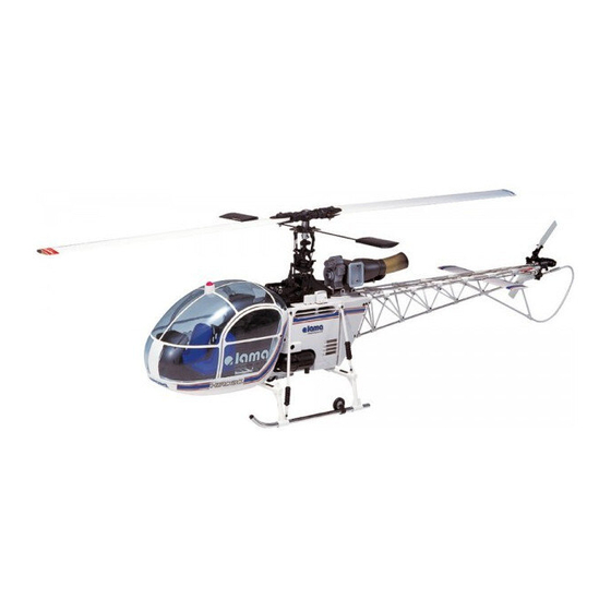
30 Lama EP instruction manual
このたびはヒロボー製品をお買いあげいただき誠に有難うございます。
この説明書はモーターの組立とMRB-III メタルローターヘッ ド組込に関する箇所
のみとなっています。
30ラマ取扱説明書の下記組立番号のページは、 30ラマ電動組立説明書を参考に
組立を行って下さい。
30ラマ電動 組立説明書
□
1 エ レベーター レバー ・ エルロ ン レバーの組立
□
2 メ イ ンフ レームの組立
□
3 コ レク ト ピ ッ チレバーの組立
□
4 サーボフ レームの組立
□
5 モーター部の組立
□
6 モーター部の取付
□
7 ウオ ッ シュアウ ト部の組立
□
8 ローターヘッ ドの組立
□
9 スワ ッ シュ プレー トの組立
□
10 ローターヘッ ド部/ウオ ッ シュアウ ト部/スワ ッ シュプレー ト部の取付
□
11 サーボの取付
□
12 ジ ャ イ ロ、 バッ テ リ ーの取付
□
13 ESC (アンプ) の取付
□
14 ローターヘッ ド部のリ ンケー ジ
□
15 コ レクティ ブピ ッ チのリ ンケー ジ
□
16 メ イ ンブレー ドの取付
□
17 ピ ッ チ/スロ ッ トルの設定
□
18 キ ャ ビンの組立
30 Lama EP instruction manual
□
1 Elevator, aileron lever assembly
□
2 Main frame assembly
□
3 Collective pitch lever assembly
□
4 Servo frame assembly
□
5 Motor assembly
□
6 Motor installation
□
7 Wash-out assembly
□
8 Rotor head assembly
□
9 Swashplate assembly
□
10 Rotor head, wash-out and swash plate installation
□
11 Servo installation
□
12 Gyro and battery installation
□
13 ESC (amp) installation
□
14 Rotor head linkage
□
15 Collective pitch linkage
□
16 Main blade installation
□
17 Pitch and Throttle setting
□
18 Cabin assebmly
注 意 Caution
本製品はスタント飛行を目的に作られたものではありません。
ロール・ループ・背面飛行などのスタント飛行は行わないでください。
ポイント
Point
ジャイロはラダーのみでも飛行可能ですが、市販の3軸ジャイロを
搭載すると、より操縦しやすくなります。
設定・接続は各ジャイロの説明書を参考に 行ってください。
Thank you for purchasing this Hirobo product.
This manual is only for Motor assembly and MRB-III metal rotor head assembly.
In the case of mounting this to the 30-scale LAMA, please refer to this 30 Lama
EP instruction manual for assembly in place of the assembly numbers of the
respective instruction manuals.
30ラマ 取扱説明書
□
⇨
1 エ レベーター レバー ・ エルロ ン レバーの組立
P11
□
⇨
4 メ イ ンフ レームの組立
P12
□
⇨
5 コ レク ト ピ ッ チレバーの組立
P13
□
⇨
6 サーボフ レームの組立
P14
□
⇨
7 エ ンジンの組立
P15
□
⇨
8 エ ンジンの取付
P16
□
⇨
P18 11 ウオ ッ シュアウ ト部の組立
□
⇨
P18 12 ブレー ドホルダーの組立
□
P19 13 ヨーク/ブレー ドホルダー部の組立
□
⇨
P20 16 スワ ッ シュ プレー トの組立
□
⇨
P21 17 ローターヘッ ド部/ウオ ッ シュアウ ト部/スワッ シュプレー ト部の取付
□
⇨
P25 22 サーボの取付
□
⇨
P26 23 受信機 ・ ジ ャ イ ロの取付
□
⇨
P26 23 受信機 ・ ジ ャ イ ロの取付
□
⇨
P28 25 ローターヘッ ド部のリ ンケー ジ
□
⇨
P31 28 コ レクティ ブピ ッ チのリ ンケー ジ
□
⇨
P34 32 メ イ ンブレー ドの取付
□
⇨
P36 34 ピ ッ チ/スロ ッ トルの設定
□
⇨
P40 39 キ ャ ビンの組立
30 Lama instruction manual
□
⇨
P11
1 Elevator, aileron lever assembly
□
⇨
P12
4 Main frame assembly
□
⇨
P13
5 Collective pitch lever assembly
□
⇨
P14
6 Servo frame assembly
□
⇨
P15
7 Engine assembly
□
⇨
P16
8 Engine installation
□
⇨
P18 11 Wash-out assembly
□
⇨
P18 12 Blade holder assembly
□
P19 13 Yoke and blade holder assembly
□
⇨
P20 16 Swashplate assembly
□
⇨
P21 17 Rotor head, wash-out and swash plate installation
□
⇨
P25 22 Servo installation
□
⇨
P26 23 Receiver and gyro installation
□
⇨
P26 23 Receiver and gyro installation
□
⇨
P28 25 Rotor head linkage
□
⇨
P31 28 Collective pitch linkage
□
⇨
P34 32 Main blade installation
□
⇨
P36 34 Pitch and Throttle Setting
□
⇨
P40 39 Cabin assebmly
This product is not intended for stunt performances.
Please do not conduct such flying stunts as rolls, loops or
inverted flight.
While flight is possible with a rudder gyro only, a commercially
available 3-axis gyro makes it easier to operate the flight
controls.
Refer to the operation manual of each gyro for the settings and
connection.
1
No. 10F50
Advertisement
Table of Contents

Related Manuals for Hirobo 30 Lama EP


Summary of Contents for Hirobo 30 Lama EP
- Page 1 30ラマ電動 組立説明書 30 Lama EP instruction manual このたびはヒロボー製品をお買いあげいただき誠に有難うございます。 Thank you for purchasing this Hirobo product. この説明書はモーターの組立とMRB-III メタルローターヘッ ド組込に関する箇所 This manual is only for Motor assembly and MRB-III metal rotor head assembly. のみとなっています。 In the case of mounting this to the 30-scale LAMA, please refer to this 30 Lama 30ラマ取扱説明書の下記組立番号のページは、...
- Page 2 フライトするためにキット 以外に必要なもの Items necessary for flying this model not (別売) included in this kit (Sold separately) 当機を楽しむためには、以下のものが必要です。 (別売) The following items are necessary in order to use the unit. (sold separately) ¥ 税抜価格 付属品 プロポセット Accessories Ttransmitter set ピ ッ チチャ ンネル SWM3サーボ...
-
Page 3: Main Frame Assembly
エレベーターレバー・エルロンレバーの組立 Elevator, aileron lever assembly M2ロッ ドエン ド M2X8PH ........2 M2X10CS M2 rod end LMエレベーターレバー LM elevator lever M2X10CS ......3 LMエレベーターシャフ ト LMエレベーターロッ ド M2X6CS ........2 LM elevator shaft LM elevator rod ø5 ボール .......2 ø5 ball Brg. ø5X8X2.5 ø4Eリング EX ø5 ボール... - Page 4 コレクトピッチレバーの組立 Collective pitch lever assembly S3X5X5カラー S3X5X5 collar M3X18PH FW ø3Xø4.5X0.5T FW ø5Xø7X0.4T コレク トピッチレバーR Collective pitch lever R M3X8PH FW ø3Xø9X1T ø6X8X4.7カラー ø6X8X4.7 collar コレク トピッチレバーL Collective pitch lever L Brg. ø6X10X3ZZ FW ø3Xø4.5X0.5T S3X5X5カラー Brg. ø6X10X3ZZ S3X5X5 collar FW ø3Xø9X1T ø6X8X4.7カラー...
- Page 5 サーボフレームの組立 Servo frame assembly M3X15皿 M3ナイロンナッ ト M3X15 disc screw M3 nylon nut M3X15皿 ........4 LM20バッテリーマウン トL148 M3X15 disc screw LM20 battery mount L148 FW ø2.6Xø7.5X0.5T M3X12皿 ........2 M3X12皿TS M3X12 disc screw M3X12 disc TS LM20ピッチサーボマウン ト LM20 pitch servo mount M3X12皿TS ......
-
Page 6: Motor Assembly
モーター部の組立 Motor assembly M3X12CS M3X8CS ........4 M3X12CS ......... 2 クラッチシュー Clutch shoe 機体に付属のクラッチシューを FW ø2.6Xø7.5X0.5T ....4 使用します。 Use the clutch shoe that is attached to the main unit. 凹みがあるほうが上になります。 The side with the cavities faces up. クラッチスペーサー4T Clutch spacer 4T SE-EPブラシレスモーター890KV SE-EP brushless motor 890KV モーターの配線方向に注意... -
Page 7: Motor Installation
モーターの取付 Motor installation M3X14CS ......... 4 M3X12皿TS ......8 M3X12 disc TS M3X14CS FW ø3Xø9X1T FWø3X9X1 ....... 4 FW ø3Xø9X1T M3X14CS 本締め Tightened completely M3X12CS及びM3X8CSはモーターの位置を 調整後しっかりと締付けてください。 Securely tighten screws M3X12CS and M3X8CS after adjusting the position of the motor. 注 意 Caution モーターマウントの取付ける向きに... - Page 8 ウォッシュアウト部の組立 ラジアスブロック Wash-out assembly Radius block 工場組立済 仮止め Temporarily ラジアス支持アーム Already assembled Radius support arm M3X12皿TS ......1 M3X12 countersunk TS M3X12皿TS M3X12 countersunk TS ヘイコウピン ø2X22 ..1 Pallarel pin ø2X22 ヘイコウピン2X22 ニードルピン ø2X15.8 ..1 Pallarel pin 2X22 Needle pin ø2X15.8 ニードルピン2X15.8 ラジアスアーム...
- Page 9 ローターヘッド部 / ウォッシュアウト部 /スワッシュプレート部の取付 Rotor head,wash-out and swash plate installation 注 意 Caution ローターヘッドの取付ネジは必ずロックタイトを M3X10CS ......1 塗布し、しっかりと締付けてください。 また、ネジの緩みがないかフライトごとに点検し てください。 M2.6X10CS ......2 Apply locktight to the screws for the rotor heads, and screw tightly. M2.6X10CS M2.6X10CS Make sure that no screws are loose before カラー4X6X2 each flight.
-
Page 10: Servo Installation
サーボの取付 Servo installation M2.6X16TS ( 座金付 ) M2.6X16TS (with washer) M2.6X16TS (座金付) .....16 M2.6X16TS (with washer) 注 意 Caution ネジの締め付けはグロメットがつぶれ ないように、注意してください。 Fasten the screws making sure not to break the grommet. エレベーター Elevator 注 意 Caution サーボの向きに注意してください。 エルロン Note the direction of the servo. ラダー... - Page 11 ジャイロ、バッテリーの取付 Gyro and battery installation 注 意 Caution 注 意 Caution ジャイロセンサー部には取付方向があります。 バッテリーはマジックテープ、 バンド等で ジャイロの取扱説明書に従って取り付けてくだ しっかり固定して ください。 さい。 Secure the battery well with Velcro The gyro sensor must be installed with the fasteners and bands, etc. correct orientation. Install it according to the gyro’s instruction manual.
- Page 12 ESC (アンプ) の取付 ESC (amp) installation 下記の図はESC (アンプ) の取付例ですので、 必要に応じて取付位置の調 An installation example is explained below for the ESC (amp). Adjust the 整又は変更を行って ください。 position of the ESC (amp) and battery as necessary. ポイント 注 意 Caution Point ESC (アンプ) は両面テープ、 マジックテープ、 バンド等でしっかり固 モーターが回っているのにローターヘッドが回らない場合はモータ...
- Page 13 ESC(アンプ)とバッテリーの接続について ESC (amp) and battery connection ESC (アンプ) 及びバッテリーは市販のコネクタ等を半田付けしてから下記の 図を参考に配線して ください。 After soldering the commercially available connector, etc., for the ESC (amp) and battery, connect the cables referring to the diagram below. 付属のバナナピン (メス) をハンダ付けし、 収縮チューブ をかぶせます。 Solder the banana connector attachment (female socket), and cover it with an elastic tube.
-
Page 14: Rotor Head Linkage
ローターヘッド部のリンケージ Rotor head linkage リンケージロッド Linkage rod ロッドエンド ...... 6 ローターヘッドASSY 上から見た図 Rod end Rotor head assembly Seen from above 回転方向 Rotation direction ラジアスブロック Radius block ピッチアームの向きに注意して下さい。 Pay attention to the orientation of the pitch arm. ラマ/シャトル Lama/Shuttle 注 意 Caution ピッチロッドはメインブレードを取付後、... - Page 15 Collective pitch linkage Collective pitch rod Rod end Check that the transmitter’s throttle stick and trim are in neutral. コレク トピッチロッ ド Collective pitch rod 不要な部分はカッ トする。 Cut out any unnecessary parts. 約8mm 90° Approx.8 mm 水平 Horizontal コレク トピッチレバー Collective pitch lever With the transmitter’s stick and trim in neutral, adjust the length of the collective pitch rod so...
- Page 16 メインブレードの取付 Main blade installation M3X15PH FW ø2.6Xø7.5X0.5T カラー3X6X12 Collar 3X6X12 M3X28CS ......3 収縮チューブを M3X15PH ......6 カッターで 切り取ります。 Cut the elastic tube エポキシ with a cutter knife. Epoxy M3ナット ......6 エポキシ接着剤 M3 nut 30分硬化型 30-min hardening type epoxy adhesive KVルートエンド...
-
Page 17: Pitch And Throttle Setting
ピッチ/スロットルの設定 Pitch and Throttle setting ピッチの設定 Pitch setting ヒロボー製ピ ッ チゲー ジ(2513-040)を使用の場合 ホールド コンディション ホバリング Condition When Hirobo pitch gauge (2513-040) is used Hold Hovering ハイピッチ High pitch ホバリング Hovering ローピッチ Low pitch ピッチゲージ Pitch gauge 注 意 Caution この設定は一般的なピッチカーブです。... - Page 18 ■ピッチカーブの設定 ■Pitch curve setting 設定の行い方はご使用の送信機の説明書をご覧ください。 For the setting method, refer to the instruction manual of the transmitter used. ループ系 ホバリング オートローテーション ロール系 Loop Hovering Auto-rotation Roll 100% 100% 100% 100% スティック:ロー スティック:ロー スティック:ロー スティック:ロー スティック:中立 スティック:中立 スティック:中立 スティック:中立 スティック:ハイ スティック:ハイ スティック:ハイ...
- Page 19 キャビンの組立 Cabin assebmly バッテリーのサイズに 合わせてキャビン背面 赤 の斜線部をカッ ト します。 Cut the shaded area on the back of the cabin 白 to fit the size of the White キャノピー battery. Windshield M2.6X12TS M2.6X6トラスTS M2.6X6 truss TS ドアー取手 Door knob M3X8TS M2.6X12TS センターマーク...
-
Page 20: Parts List
パーツリスト Parts list 0402-688 2522-004 (ラマ/シャトル) (Lama/Shuttle) 2532-003 2532-010 2524-001 2532-031 2532-051 2525-007 2529-008 0402-692 2521-065 2532-039 2500-060 2533-029 0402-691 2506-007 2532-051 0402-690 2500-079 2532-021 0406-057 (右) (Right) 2505-006 0402-693 2533-023 0402-673 2533-001 2506-044 2532-028 2525-007 0402-650 2521-039 2505-002 0402-131 ( ラマ/シ ャ ト ル) 2509-006 0402-689 (Lama/Shuttle) - Page 21 コー ド No. 品名 入数 税抜価格 ( 円 ) 備考 Code No. Part Q'ty Price (Yen) Remarks JI-16 オートロクラッチセット 1 式 0402-016 3,000 JI-16 Auto-rotation clutch set 1 set MRB-III シャトル用メインマスト MRB-III シャトル、ラマ用 0402-131 MRB-III main mast for shuttle For MRB-III shuttle and Lama SE ベベルギヤ...
- Page 22 0305-009 2505-006 2506-019 2525-006 2506-044 2532-031 2535-001 2538-007 0305-010 2525-006 0305-012 2532-031 2534-012 0305-013 0305-011 2534-007 2532-004 0305-014 0305-016 0305-006 0305-015 2532-004 2506-044 0305-007 2506-010 2505-006 2506-010 2538-003 2506-044 2532-004 0305-006付属 Included with 0305-006 2532-002...
- Page 23 Tapping screw M3X10 タッピングスクリュー M3X12 皿クロ 2535-001 Tapping screw M3X12 disc サラビス M3X12 2538-003 Disc screw M3X12 サラビス M3X15 2538-007 Disc screw M3X15 【お知らせ】 URL https://www.hirobo.com/ 2020年3月にオフ ィシャルオンラインショップをオープンいたしました。 お支払い方法が、 銀行振り込み、 クレジッ ト決済、 コンビニ決済から選べるようになり、 お買い求めやすく なりました。 電動機、 エンジン機にかかわらず、 キッ ト、 スペアパーツ、 OPパーツを揃えています。 商品のご購入はもちろん、 商品詳細確認にもご利用ください。...
- Page 24 3-3-1 SAKURAGAOKA, FUCHU-SHI, 1 〒726-0006 広島県府中市桜が丘三丁目 番地 HIROSHIMA-PREF., JAPAN 〒726-0006 TEL : (0847) 44-9088㈹ FAX : 47-6108 TEL : 81 ・ 847 ・ 44-9088 FAX : 81 ・ 847 ・ 6108 注 意 Caution ① 本書の内容の一部または全部を無断で転載することは禁止されています。 ② 本書の内容については、 将来予告なしに変更することがあります。 ③ 本書の内容について万全を期しておりますが、 万一ご不審な点や誤り、 記載もれなどお気付きのことが ありましたら、...
Need help?
Do you have a question about the 30 Lama EP and is the answer not in the manual?
Questions and answers