Table of Contents
Advertisement
Quick Links
■ 組立前に必ずこの説明書を最後まで、よくお読みになり、正
しくお使いください。特に、「1. 組立を始める前に必ずお読
みください」は、組立前及び飛行前に必ずお読みください。
■ この説明書は、大切にお手元に保管してください。
※ 製品改良のため、予告なく仕様を変更する場合があります。
■ Before assembly, make sure to completely read this instruction
manual. In particular, make sure to read the "1. Read before
Assembly" section before assembly and operating the unit.
■ Keep this instruction manual in a handy, safe place.
※ In order to make improvements to this product, specifications
may be altered without prior notice.
別売品 Sold separately
■メインブレード:680-760mm
■テールブレード:90-105mm
■バッテリー:リチウムポリマーバッテリー 5 cell (18.5V)
又は6 cell (22.2V)×2パック (4800∼5500mAh推奨)
搭載可能サイズ (幅60mm、 高さ50mm、 長さ200mm)
■モーター:ブラシレスモーター ø6シャフト KV450∼630
■ESC (アンプ) :10 cell又は12 cell対応 120A以上推奨
■プロポセット: 前後1:1のスワッシュモード機能の付いた送信機。
3サーボ+ラダーサーボ・3軸 (エルロン・ エレベーター・ピッチ) ジャイロ
■Main blade: 680-760mm
■Tail blade: 90-105mm
■Battery: Lithium polymer battery 5 cell (18.5V) or 6 cell (22.2V)×2 packs
(4800∼5500mAh recommended)
Mountable size (Width 60 mm, height 50 mm, length 200 mm)
■Motor: Brussless motor ø6 shaft KV450-630
■ESC (amp): 10 cell or 12 cell, 120 A or higher recommended
■Transmitter set: A transmitter with the swash mode function having front and back ratio of 1:1.
3 servos + rudder servo and 3 axis (aileron, elevator, pitch) gyro
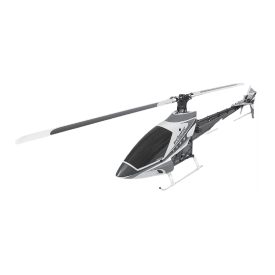
■主要諸元
● 全備重量 (参考) : 約5,700g
(使用するバッ テ リ ー ・ ESC ・ ブレー ド等によ り異な り ます。 )
■SPEC
● Overall weight (reference): Approx. 5,700g
(Varies depending on the type of battery, ESC,
blade or other parts used.)
200mm
417mm
※0414-538 WCカーボン対称メインブレード L=720使用時
※0404-721 WCカーボンテールブレード L=90使用時
※With 0414-538 WC carbon symmetric main blade L=720
※With 0404-721 WC carbon tail blade L=90
MADE IN JAPAN
1,490mm
2014
C
No.10G41
Advertisement
Table of Contents

Related Manuals for Hirobo jm2-0307903


Summary of Contents for Hirobo jm2-0307903
- Page 1 ■ 組立前に必ずこの説明書を最後まで、よくお読みになり、正 ■主要諸元 しくお使いください。特に、「1. 組立を始める前に必ずお読 ● 全備重量 (参考) : 約5,700g (使用するバッ テ リ ー ・ ESC ・ ブレー ド等によ り異な り ます。 ) みください」は、組立前及び飛行前に必ずお読みください。 ■SPEC ■ この説明書は、大切にお手元に保管してください。 ● Overall weight (reference): Approx. 5,700g ※ 製品改良のため、予告なく仕様を変更する場合があります。 (Varies depending on the type of battery, ESC, ■ Before assembly, make sure to completely read this instruction blade or other parts used.) manual.
- Page 2 組立を始める前に安全のために必ず For safety reasons, observe the following お守りください。 precautions before assembly. Thank you very much for purchasing a Hirobo product. In order to be このたびは、ヒロボー製品をお買上げいただき、ありがとうござい able to use this product safely, please read this manual before flying the ます。 helicopter. Please fly the helicopter safely observing all rules and 安全にお使いいただくために、飛行前にこの取扱説明書を最後まで...
- Page 3 8. Use genuine parts. 9. モーターを回さないで、各部の操作方法を練習してください。 To reduce the risk of accidents and injuries, do not use parts other than those ◆ モーターを回す前に、各部の操作方法を練習してください。 shown in this instruction manual or in Hirobo catalogs. ◆ 操作を充分に修得するまではモーターを回さないでください。 9. With the motor off, practice how to operate each part. ◆ 機械の動きに異常がみられる場合もモーターを回さないでくださ...
- Page 4 Store in a dry place out of the reach of children. 3. 修理は、お買上げの販売店、または直接弊社までお申し付けくだ 3. Inquire about repairs at the store from where you purchased the product or さい。 at the engineering services section of Hirobo’s Sales Department. ◆ 修理の知識のない方や専用工具を持っていない方が修理をすると、 Individuals lacking proper knowledge or tools necessary for repairs may 十分な性能を発揮しないだけでなく、事故や怪我の原因となり...
- Page 5 無線操縦ヘリコプターを安全に For safe handling of the radio controlled helicopter お取扱いいただくために In addition to the standard precautions previously mentioned regarding radio 先に、無線操縦模型として共通の注意事項を述べましたが、ヘリコプ controlled models, please observe also the following precautionary items which ターの場合、さらに次に述べる注意事項を守ってください。 are specific to helicopters. 警告 WARNING For real aircraft, strict pre-flight inspections are mandatory. The radio 実機の場合、飛行前には厳しい点検が義務付けられています。無線操...
- Page 6 警告 WARNING フライト中の安全確認 In-flight safety check 1. Check that there are no objects in the surrounding area that may get 1. 飛行するときは周辺に当たるものや、巻き込まれそうなものがな entangled or struck by the unit during flight. いか確認してください。 2. Check that there are no other operators in the surrounding area using the 2. 周囲に同じ周波数の使用者がいないことを確認して、送信機のス...
- Page 7 For the safe operation of electric models 電動模型の安全について 警告 WARNING ご使用の前に Before using the unit Never leave equipment such as the transmitter, dry battery, battery, charger 送信機、乾電池、バッテリー、充電器、機体等を幼児や子供の手の or flying unit in a location that can be accessed by the inquisitive hands of 届くところに放置しないでください。...
- Page 8 この説明書の見方 How to use this instruction manual 組立前の注意 Pre-assembly precautions 1. 組立る前に説明書を良く読んで、おおよその構造及び組立手順を 1. Before assembly, read the instruction manual thoroughly and familiarize yourself with the unit’s structure and assembly procedures. Failure to 理解してから組立に入ってください。正しい組立を行わないと、 assemble the unit properly may not only result in impaired performance 本来の性能を発揮できなくなるばかりでなく、大変危険です。...
- Page 9 How to read part types and sizes ネジの種類とサイズの見方 The symbols shown in this instruction manual are shown as below: 本説明書の文中に記載している記号は、次の約束になっています。 The unit of measurement is the millimeter. ● 単位はミリメートルです。 ナベ頭ビス セットスクリュー ø5ボール Pan-head screw Set screw ø5 ball 12mm ø5ボール M3X12PH M3X4SS ø5 ball...
- Page 10 フライトするためにキット以外に必要なもの Items necessary for flying this model not (別売) included in this kit (Sold separately) The following items are necessary in order to use the unit. (sold separately) 当機を楽しむためには、以下のものが必要です。 (別売) ¥ 税抜価格 スワッシュモード対応プロポセット ピ ッ チチャ ンネル SWM3サーボ Swash mode compatible SWM3 servo Pitch channel programmable transmitter set...
- Page 11 Useful tools あると便利な周辺用具 ¥税抜価格 ブレードサポート Blade support 2513-039 ¥500 Names of each component 各部の名称 テールブレード(別売) Tail blade (sold separately) メインブレード(別売) 水平尾翼 Main blade (sold separately) Horizontal tail fin (stabilizer) メインローターヘッド テールブーム Main rotor head Tail boom 垂直尾翼 Vertical tail fin (stabilizer) テールブームブレース...
- Page 12 2. 組立編 Assembly M4X4SS カウンターギヤ部の組立 ベアリングホルダーø13を取付 Counter gear assembly けた時に、 上下にアソビが無い テールプーリー17T (3GT D6) 様に締付けてください。 Tail pulley 17T (3GT D6) Tighten screw so there is no up/ down play when bearing holder ø13 is assembled. カウンターギヤシャフトD6 M4X4SS ........ 2 Counter gear shaft D6 M3X5SS .........
- Page 13 メインフレーム の組立 Main frame assembly M3X8CS ........ 4 ポイント Point M3X10CS ......4 フローティングアングルは、それぞれA・Bの印字がされ ています。 There are floating angles that are labeled “A” & “B.” M3X8皿ビス ......4 M3X8 countersunk screw FW ø2.6Xø7.5X0.5T ....8 M3X60ク ロス メ ンバー .... 2 (EX ø3強化ワ...
- Page 14 サーボフレーム・メインフレーム の組立 Servo frame and main frame assembly M3X26クロスメンバー カラー3X8X17 M3X26 cross member Collar 3X8X17 M3X8CS ........ 2 カラー3X8X17 Collar 3X8X17 M3X25CS ......6 M3X26クロスメンバー カラー3X8X17 M3X28CS ......16 M3X26 cross member Collar 3X8X17 カラー3X8X17 M2.6X6皿ビス ...... 6 Collar 3X8X17 M2.6X6 countersunk screw FW ø2.6Xø7.5X0.5T ...
- Page 15 ポイント Point メインフレームを定盤の上に置いて、水平、垂直を出します。 11 で Place the main frame on the surface plate and adjust its メインマストを使い、3つのベアリングにスムーズに通ることを確認 horizontal and vertical position. しながら各ネジを締込みます。 In procedure 11 , while making sure that the main mast fits into the three bearings smoothly, screw all of the necessary bolts.
- Page 16 SWM フロントレバー 、SWMエルロンレバーの組立 SWM front lever and SWM aileron lever assembly EX ø5ボール M2X6CS EX ø5 ball E3 SWMエルロ ン レバー FW ø1.7 E3 SWM aileron lever M2X6CS FW ø1.7 EX ø5ボール M2X6CS EX ø5 ball カ ラー5X8X2.5 FW ø1.7 Collar 5X8X2.5 E3 SWMエレベー...
- Page 17 テールブームホルダー、サーボマウント の 取付 Tail boom holder and servo mount installation M3X35CS ......2 ポイント Point M3X10CS ......2 M 3 X 3 5 C S な ど の ネ ジ が 切 っ て な い 部 分 に F W ø2.6Xø7.5X0.5Tが入らない場合は、...
- Page 18 モーター 部の組立 EX-EPピニオンギヤ (11T) Motor assembly EX-EP pinion gear (11T) ギヤ比 EX-EPピニオンギヤ (10T) Gear ratio EX-EP pinion gear (10T) ギヤ比 メインギヤ ピニオ ンギヤ M3X8CS ........ 8 Gear ratio Main gear Pinion gear EX-EPピニオンギヤ (9T) 1:12 EX-EP pinion gear (9T) 1:10.8 108T M4X8ボタンボルト...
- Page 19 ランディングギヤの 組立 Landing gear assembly M3Uナット M3X10CS ......4 M3 U nut M3Uナット M3 U nut M2.6X10CS ......4 M3Uナット M3 U nut M2.6ナイロンナット ... 4 M2.6 nylon nut M3 Uナット ......4 M3 U nut フ ローテ ィ ン グゴム Floating rubber FW ø3Xø9X1 FW ø3Xø9X1T .......
- Page 20 メインマスト の組立 メインマスト Main mast Main mast assembly 186mmの穴を使用して メインマスト Main mast く ださい。 Use holes for 186 mm length. M3.5X10CS ......2 M2.6X8CS ......1 工場組立済 (Pre-assembled into our factory) ø10ハー ドグ リ ッ プマス ト ロ ッ ク M2.6X12皿ビス...
- Page 21 ウォッシュアウト ASSY の組立 Assembling the washout assembly 注 意 Caution ウォッシュアウトコントロールアームの 向きに注意してください。 Note washout control arm orientation. M3X22CS ......1 ø1.5 Eリング ø1.5 E-ring SSLウオッシュコントロールアーム SSL wash control arm M3X15CS ......1 溝付き平行ピンø2X11.8 Grooved parallel pin ø2X11.8 カラー3X4X8.5F ....2 ラジアスアームP=25 Radius arm P=25 Collar 3X4X8.5F...
- Page 22 ヨーク/ブレードホルダー部の組立 Yoke and blade holder assembly 警 告 Warning 飛行前にはM5X10ボタンボルトが緩んでいないかを点 警 告 Warning 検してください。 スピン ドルのネジき り部に必ずネジロッ ク剤 (高強度タイプ) を塗布し、 ボタンボル トM5X10 また、 M5X10ボタンボル トは定期的に交換してく ださい。 緩んだボルトは疲労亀裂の起こりやすい状態となり、 を40~45kg•f/cmの締め付け トルクでし っかり と締め付けてく ださい。 破損の原因となります。 ネジロッ ク剤を塗布しなかったり、 ボル トがし っかり と締めつけられていなかった場合、 ボル ト Before flying the unit, please check that the button の脱落や疲労による破損によ...
- Page 23 ローターヘッド部/ウォッシュアウト部/スワッシュプレート 部 の取付 Rotor head, washout, and swashplate installation ボタンボルトM4X8 Botton bolt M4X8 M4X8ボタンボルト ..... 2 M4X8 button bolt M3X12皿ビス ....... 1 M3X12 countersunk screw M2.6X10CS ......2 カラー3X5X1 ......1 Collar 3X5X1 図 -1 M2.6X10CS Fig. 1 フ レーム Frame ラ...
- Page 24 テールケース部の 組立 M2.6X6CS Tail case assembly M3X8CS ........ 2 M3X8CS Brg. ø6Xø13X5 FW ø6Xø8X0.1T 工場組立済 M3X5CS ........ 6 (すきま調整用) Pre-assembled M3X5CS EX ø6テールシャフト M2.6X6CS ......4 EX ø6 tail shaft EX テールプーリー18T EX tail pulley 18T クロスメンバーM3X14 ..1 M3X14クロスメンバー Cross member M3X14 M3X14 cross member FW ø6Xø8X0.1T...
- Page 25 EX テールピッチプレートの 組立 EX tail pitch plate assembly 工場組立済 Pre-assembled ミゾ付き平行ピンø1.5X8 Grooved parallel pin ø1.5X8 EXテールピッチプレート Eリング1.2mm Eリング1.2mm EX tail pitch plate E-ring 1.2 mm E-ring 1.2 mm テールリンク ミゾ付平行ピンø1.5X8 Tail link Grooved parallel pin ø1.5X8 EXテールピッチプレートボス EX tail pitch plate boss カラー7X8X4 テールリンク...
- Page 26 テールブームパイプ部の 取付 Tail boom pipe installation M3X8CS ........ 4 M2.6X6CS ......1 FW ø3Xø9X1T ...... 2 M2.6X6CS FW ø3Xø9X1 FW ø3Xø9X1 M3X8CS EX尾翼バンド M3X8CS EX tail fin band 八角テールブームパイプL=895 Octagonal tail boom pipe L=895 テールブームブレース部の組立 Tail boom brace assembly M2.6X8CS ......4 M2.6X8CS M2.6X8CS エポキシ接着剤...
- Page 27 テールブーム の 取付 Tail boom installation M2.6X8TS-1 ......6 この穴を使用する Use this hole. 8角テールブームパイプ Octagonal tail boom pipe 注 意 Caution ラダーコントロールガイド 8角テールブームパイプが入りにくいときは、 Rudder control guide マイナスドライバー等で隙間を少し広げて入 れて下さい。 If it is difficult to insert the octagonal tail boom, use a slotted screwdriver etc to wide the gap slightly, and then insert it.
- Page 28 尾翼 の 取付 Attachment of the tail fin M3X35CS M3X35CS ......2 M3X25CS ......2 注 意 Caution 水平尾翼 Horizontal stabilizer 尾翼バンド(L)は下図のようになるよ M3X18CS ......4 うに取付けてください。 Install the lower horizontal fin band as shown below. M3ナイロンナット ....8 前 M3 nylon nut Front 傾きがあり...
- Page 29 サーボ の取付 Servos installation M2.6X10CS ......12 サーボプレート Servo plate サーボプレート ....14 Servo plate M2.6X12CS ......12 (サーボプレー ト を2枚はさんで使う場合) (When using two servo plates) SWM1サーボ M2.6X10CS SWM1 servo (エルロンチャンネルへ) (To the aileron channel) M2.6X16TS(座金付) ..4 M2.6X16TS (with washer) サーボ取付ナット...
- Page 30 クロスメンバー・ジャイロマウント の取付 ポイント Cross members and gyro mount installation Point キャビンを取付ける穴位置によって キャビンクロスメンバーM3X6の取付 カラー3X8X2 位置を変更してください。 Collar 3X8X2 39 キャ ビンの取付を参照してく ださい。 リンケージやメインギヤが Change the attachment position of キャビンに接触する場合に the cabin cross member M3X6 使用してください。 キャビンクロスメンバー M3X6 Use it so the linkage and main depending on the position of the Cabin cross member M3X6 gear come into contact with...
- Page 31 受信機 ・ジャイロ の取付 Receiver and gyro installation 注 意 Caution 注 意 Caution ジャイロセンサー部には取付方向があります。 テープを貼り付ける前に、 貼り付け部分 ジャイロの取扱説明書に従って取り付けてください。 の 汚 れなどを十 分 に拭き取ってくださ Gyro sensor components should be installed as い。 キャビンダンパーゴム ... 4 per the directions according to the manufacture of Before adhering double sided tape to Cabin damper rubber your gyro.
- Page 32 ワンタッチバッテリーマウント の 取付 One touch battery mount installation スプリング 注 意 Caution Spring M3X3SS M3X3SS ......... 2 M3X3SSはスライドラッチピンのDカット部に 合わせて締付けてください。 Adjust the slide latch pin so that M3X3SS is スプリング ......1 tightened on the D-cut part of the pin. Spring スライドラッチレバー...
- Page 33 リヤバッテリーマウント の取付 Rear battery mount installation 斜めに取付ける場合 水平に取付ける場合 When mounted at an angle When mounted so it is level M2.6X6皿ビス M3X8CS ........ 8 M2.6X6皿ビス M2.6X6 countersunk screw M2.6X6 countersunk screw EX-EPリヤバッテリー M2.6X6皿ビス ...... 8 プレート M2.6X6 countersunk screw EX-EP rear battery plate FW ø2.6Xø7.5X0.5T ....
- Page 34 送信機の初期設定とサーボ の 動作確認 Transmitter initial setting and servo movement Swash mode requires the initial setting of the transmitter for swash mixing. スワッシュモードでは、スワッシュミキシングのための送信機の初 期設定が必要です。 チェック Check ピッチカーブ、スロットルカーブの入力は 38 でおこないます。 Inputting the pitch curve and throttle curve is carried out in 38 先にピッチカーブ、スロットルカーブを入力すると、サーボホーン...
- Page 35 ローターヘッド周りの リンケージ Rotor head linkage M2ロッドエンド ....8 M2 rod end エルロンレバースワッシュロッド Aileron lever swash rod ピッチロッド Pitch rod ピッチロッド Pitch rod エルロンレバースワッシュロッド Aileron lever swash rod ピッチロッド(2セット) Pitch rod (2 rods) 55mm 注 意 Caution 約34mm ブ レ ー ド 取 付 後 、 実 際 に ピ ッ チ を Approx.
- Page 36 SWM の リンケージ-1 SWM linkage-1 SWMロッド①(2セット) M2X6CS ........ 2 SWM rod ① (2 sets) 90mm EX ø5ボール ......2 EX ø5 ball 約76mm Approx. 76mm M2ナット ......2 M2 nut M2ロッドエンド ....4 M2 rod end FW ø1.7 ........2 このページ以降のサーボホ...
- Page 37 SWM の リンケージ-2 SWM linkage-2 SWMロッド②(2セット) M2X6CS ........ 2 SWM rod ② (2 sets) 70mm EX ø5ボール ......2 EX ø5 ball 約55mm Approx. 55mm M2ナット ......2 M2 nut M2ロッドエンド ....4 M2 rod end FW ø1.7 ........2 M2ナット...
- Page 38 SWM の リンケージ-3 SWM linkage-3 SWMロッド③(2セット) M2X6CS ........ 2 SWM rod ③ (2 sets) 110mm EX ø5ボール ......2 EX ø5 ball 約97mm Approx. 97mm M2ナット ......2 M2 nut M2ロッドエンド ....4 M2 rod end FW ø1.7 ........2 M2ナット...
- Page 39 ラダーの リンケージ Rudder linkage M2X6CS ........ 1 この穴を使用する EX ø5ボール ......1 Use this hole. EX ø5 ball 下図のようにラダーコントロールガイドの位置をラダー コントロールロッドにそってずらしながら合わせます。 M2ナット ......1 Position the rudder control guide by sliding it along the M2 nut rudder control rod as shown below. M2ロッドエンド...
- Page 40 メインブレードの 組立 Main blade assembly メインブレード(別売) Main blade (sold separately) ø5ドラッグボルト ....2 ø5 drag bolt ø5ドラッグボルト ø5 drag bolt ブレードホルダー M4ナイロンナット ....2 Blade holder M4 nylon nut SSZブレードスペーサー3T SSZ blade spacer 3T メインブレードのバランスを取ります。 M4ナイロンナット Balance the main rotor blade. M4 nylon nut 注:...
- Page 41 配線図 Wiring diagram ポイント バッテリーやESCの取付に付属の面ファスナーを使います。 Point また、メカクッションバンドを使ってバッテリーを固定します。 Use the hook-and-loop fastener included for the battery and the ESC 付属の面ファスナーはカットしてご使用ください 。 installation. Cut and use the hook-and-loop fastener that is included. In addition, use the mechanical cushion band and secure the battery. オス...
- Page 42 ESC (アンプ) とバッテリーの接続について ESC (amp) and battery connection ESC(アンプ)及びバッテリーは市販のコネクタ等を半田付けしてか 警 告 Warning ら下記の図を参考に配線してください。 After soldering the commercially available connector, etc., for the ESC 思いがけない事故を防ぐために、バッテリーと (amp) and battery, connect the cables referring to the diagram below. ESC(アンプ)はフライトする直前に接続し、 フライトが終わったらただちにコネクタを外し てください。 I n o r d e r t o a v o i d p o t e n t i a l a c c i d e n t s , 市販のバナナピン(メス)をハンダ付けし、収縮...
- Page 43 ヨークのドーム下の穴に差し込み、 M4X4セットスクリューで動かない程 必ずヒロボー製ピッチゲージ(2513-040)を使用してください。 度に軽く止めます。 For best results, use Hirobo’s pitch gauge 2513-040. Insert the ø2X180 pitch horizontal rod into the hole on the bottom of the yoke dome and lightly fasten using the M4X4 set screws so that it doesn't move.
- Page 44 ■ピッチカーブの設定 ■Pitch curve setting (This data originated from the use of a programmable transmitter.) (このデーターはコンピュータプロポを使用したものです。) * It may vary depending on the ESC (amp), main unit and battery. ※ESC(アンプ)、機体、電池等により変化します。 General guidelines. 一般的な目安です。 コンディション ホバリング オートローテーション Condition (ループ系) (ロール系) スケジュールF Hovering Auto-rotation Roop Roll...
- Page 45 キャビンの取付 Cabin installation キャビンの印から5mm下がった所に穴開け ■キャビンの加工 ■水洗い Make a hole 5mm below the mark on cabin. ø10穴開け Cutting of the cabin Washing Make ø10 holes EX-EPキ ャ ビン ク ロス メ ンバーベース 約5 mm EX-EP cabin cross Approx. 5 mm member base キャビン...
- Page 46 デカールの貼付け Decal attachment パッケージを参考に、デカールを貼ってください。 Attach the decal by referring to the package, etc. キャビン Cabin ワンポイント One point 大型のデカールを貼る際には、デカールの粘 面とキャビンの両方に薄いセッケン水や、市 販の自動車用品ウィンドフィルム貼りスプレ ー等を吹きかけてください。 デカールの位置決めが容易になり、また気泡 ができにくくなるので、きれいに美しく貼る ことができます。 また、曲面に貼付ける場合、同時にドライヤ ーを用いて温めると、形状に合わせやすくな ります。 When attaching large decals, splash dilute soap water or commercial spray for window films of auto supply on both the viscous surface of decals and the cabin.
- Page 47 FAX ( ) ( ) コードNo 品 名 単 価 数 量 金 額 - - - - - ①パーツ代金の合計 ②送料 (代引手数料込) ご注文はFAXにてお願い し ます。 合計額 (①+②) ヒロボー株式会社(パーツ係) + 〒726-0006 広島県府中市桜が丘3-3-1 ③消費税 (合計額×税率) FAX:(0847)47-6108 = 注文TEL:(0847)40-0088 http://model.hirobo.co.jp/ お支払金額=合計額 (①+②) +③...
- Page 48 0414-578 0414-544 2531-003 2531-001 0414-571 2539-017 2506-044 2500-090 0414-462 2539-029 2500-090 2506-044 0414-520 0414-459 2532-051 2539-017 0414-458 2507-001 2533-030 0414-543 2509-009 0414-467 2532-007 0414-561 2500-073 2531-006 2500-073 2521-094 0414-543 2507-001 2531-006 0414-467 2507-001 2509-009 2532-015 2500-044 2532-055 2529-003 0414-525 2506-035 0414-519 2524-001 2521-074...
- Page 49 コードNo. 品名 入数 税抜価格(円) 備考 Code No. Part Q'ty Price (Yen) Remarks SSZ-IVダンパーキャップ ネジ付 0414-458 1,600 SSZ-IV damper cap With screws SSZ-IVダンパーゴム#80 0414-459 1,000 SSZ-IV damper rubber #80 SSZ-IVセンターピン 0414-462 SSZ-IV center pin ラジアスアームP25 0414-467 Radius arm P25 SSZ-Vブレードホルダー 0414-519 8,600 SSZ-V blade holder SSZ-Vフェザリングスピンドル...
- Page 50 2507-001 0414-543 2509-009 0414-467 2532-007 0414-471 2500-073 0414-561 2531-006 2500-073 2521-094 0414-543 2507-001 2531-006 2533-029 2530-014 0414-467 2532-031 2507-001 2509-009 2530-014 2532-015 0414-576 2532-031 2525-007 0414-312 0307-025 2532-030 0414-377 2500-100 2500-049 0307-021 2506-059 0307-009 0307-010 0307-011 0307-023 2531-003 2532-002 2539-029 2532-002 0414-475 2538-012...
- Page 51 コードNo. 品名 入数 税抜価格(円) 備考 Code No. Part Q'ty Price (Yen) Remarks EX-EP モーターマウント 0307-008 5,500 EX-EP motor mount EX-EP ピニオンギヤ 9T 0307-009 4,000 EX-EP pinion gear 9T EX-EP ピニオンギヤ 10T 0307-010 4,000 EX-EP pinion gear 10T EX-EP ピニオンギヤ 11T 0307-011 4,000 EX-EP pinion gear 11T...
- Page 52 2532-031 2525-006 2506-017 2532-039 0414-431 2506-044 0414-182 2511-003 0414-532 2506-032 2505-020 2500-085 2506-032 2506-021 2521-083 2500-113 2500-085 2538-003 2506-017 2525-006 2532-031 2531-003 2506-032 0414-433 2506-044 2521-109 2532-002 2500-057 2506-021 0414-532 0414-434 2532-030 2521-061 2532-002 2505-006 2506-044 2506-044 2532-002 2522-007 0412-179 2537-002 2505-015 2522-006...
- Page 53 コードNo. 品名 入数 税抜価格(円) 備考 Code No. Part Q'ty Price (Yen) Remarks サーボプレート 0412-179 Servo plate EX SWMレバーステー BRG圧入済 0414-182 2,800 EX SWM lever stay Bearing pressed. E3 SWMエレベーターレバー 1式 0414-431 8,000 E3 SWM elevator lever 1 set E3 SWMレバーシャフト 0414-433 E3 SWM lever shaft E3 SWMエレベーターアーム...
- Page 54 0414-200 2539-011 2500-079 2521-098 2532-001 2539-010 2506-038 2506-044 0307-014 0412-199 2531-003 0307-019 2532-003 2521-098 2505-004 2532-002 0307-019 0414-572 0412-199 0307-027 2506-044 2532-002 2532-001 0307-028 2521-090 0414-378 2531-002 2511-003 2506-038 0414-200 2534-003 2500-079 0307-015 2521-090 0414-377 0307-001 2500-100 2506-044 2511-003 0414-435 0403-022 2506-044 2532-002...
- Page 55 コードNo. 品名 入数 税抜価格(円) 備考 Code No. Part Q'ty Price (Yen) Remarks EX-EPサーボフレーム 0307-001 22,000 EX-EP servo frame EX-EP リヤ バッテリープレート 0307-003 4,000 EX-EP rear battery plate EX-EP ESC マウントプレート 0307-005 3,000 EX-EP ESC mount plate EX-EPフロントバッテリープレート 0307-006 5,000 EX-EP front battery plate EX-EPメカプレート...
- Page 56 2506-005 2500-051 0412-147 0412-157 0414-546 2539-015 2507-005 0414-547 2509-025 0414-580 2506-017 2525-006 2500-051 2532-031 2532-039 2506-005 2500-120 0414-548 2521-146 2500-120 2500-079 0414-549 2506-038 0414-550 0414-572 2504-032 0414-442 2511-002 0414-373 2506-038 0414-495 2531-002 2500-079 2529-010 0414-442 2506-021 2500-082 2532-039 2500-055 2506-032 2532-028 2532-002 2532-028...
- Page 57 コードNo. 品名 入数 税抜価格(円) 備考 Code No. Part Q'ty Price (Yen) Remarks SDテールピッチレバーセット 1式 0412-147 1,000 SD tail pitch lever set 1 set テールピッチレバーカラー 0412-157 Tail pitch lever collar ラダーコントロールガイド 1式 0414-137 Rudder control guide 1 set EX2カーボンテールピッチレバーステー 0414-373 EX2 carbon tail pitch lever stay EX2テールユニットホルダー...
- Page 58 2532-002 0414-334 0414-333 0414-186 0412-199 2532-012 0414-189 0414-190 2505-006 2532-002 0404-722 2506-010 2521-069 2532-039 0414-150 2506-010 2532-038 2505-006 2532-008 2532-002 0414-328 2505-006 0404-796 2532-030 2513-062 ( キイ ロ) (Yellow) 2506-044 2505-006 2513-098 2532-030 0414-575 0404-796...
- Page 59 コードNo. 品名 入数 税抜価格(円) 備考 Code No. Part Q'ty Price (Yen) Remarks WC尾翼バンド 0404-722 3,200 WC stabilizer hand テールブームブレースターミナル 98 0404-796 Tail boom brace terminal 98 SDキャビンダンパーゴム 0412-199 SD cabin damper rubber ホリゾンタルフィンと干渉する場合は、干渉する部分をヤ 1 式 水平尾翼バンド スリ等で削ってください。 0414-150 Horizontal fin band 1 set Remove interfering portions with a file if there is interference with the horizontal fin.
- Page 60 注意 Note ①本書の内容の一部または全部を無断で転載することは禁止されています。 ②本書の内容については、将来予告なしに変更することがあります。 ③本書の内容について万全を期しておりますが、万一ご不審な点や誤り、記載もれなどお気付 きのことがありましたら、ご一報くださいますようお願いいたします。 ④運用した結果については③項にかかわらず責任を負いかねますので、ご了承ください。 ①Reproduction of this manual, or any part thereof, is strictly prohibited. ②The contents of this manual are subject to change without prior notice. 平成26年12月 初版発行 ③Every effort has been made to ensure that this manual is complete and correct. Should there, 平成26年12月...
Need help?
Do you have a question about the jm2-0307903 and is the answer not in the manual?
Questions and answers