Table of Contents
Advertisement
Quick Links
GE
Digital Energy
GE Digital Energy
650 Markland Street
Markham, Ontario
Canada L6C 0M1
Tel: +1 905 927 7070 Fax: +1 905 927 5098
Internet:
http://www.GEDigitalEnergy.com
*1601-0115-Y2*
Addendum
B90 Low Impedance Bus
Differential System
UR Series Instruction Manual
Manual P/N: 1601-0115-Y2 (GEK-113660A)
E83849
LISTED
IND.CONT. EQ.
52TL
B90 revision: 7.0x
836771A2.CDR
GE Multilin's Quality Management
System is registered to ISO
9001:2008
QMI # 005094
UL # A3775
Advertisement
Table of Contents

Related Manuals for GE B90 UR Series


Summary of Contents for GE B90 UR Series
- Page 1 GE Digital Energy LISTED 650 Markland Street IND.CONT. EQ. 52TL Markham, Ontario GE Multilin's Quality Management Canada L6C 0M1 System is registered to ISO 9001:2008 Tel: +1 905 927 7070 Fax: +1 905 927 5098 QMI # 005094 UL # A3775 Internet: http://www.GEDigitalEnergy.com...
- Page 2 The contents of this manual are the property of GE Multilin Inc. This documentation is furnished on license and may not be reproduced in whole or in part without the permission of GE Multilin. The content of this manual is for informational use only and is subject to change without notice.
-
Page 3: Table Of Contents
TYPICAL WIRING....................3-6 3.2.2 DIELECTRIC STRENGTH ................3-12 3.2.3 CONTROL POWER ..................3-12 3.2.4 CT AND VT MODULES ................... 3-13 3.2.5 CONTACT INPUTS AND OUTPUTS ............... 3-14 3.2.6 RS232 FACEPLATE PORT ................3-22 GE Multilin B90 Low Impedance Bus Differential System... - Page 4 FLEX STATE PARAMETERS ................5-57 5.2.16 USER-DEFINABLE DISPLAYS ................5-58 5.2.17 DIRECT INPUTS AND OUTPUTS..............5-60 5.2.18 INSTALLATION ....................5-68 5.3 SYSTEM SETUP 5.3.1 AC INPUTS.......................5-69 5.3.2 POWER SYSTEM ....................5-70 5.3.3 FLEXCURVES™ ....................5-71 5.3.4 BUS ........................5-78 B90 Low Impedance Bus Differential System GE Multilin...
- Page 5 IEC 61850 GOOSE INTEGERS................. 6-7 6.2.12 DIRECT INPUTS....................6-7 6.2.13 DIRECT DEVICES STATUS................6-8 6.2.14 REMAINING CONNECTION STATUS .............. 6-8 6.3 METERING 6.3.1 METERING CONVENTIONS ................6-9 6.3.2 BUS ZONE......................6-9 6.3.3 CURRENTS ..................... 6-10 GE Multilin B90 Low Impedance Bus Differential System...
- Page 6 9.5 SATURATION DETECTOR 9.5.1 CT SATURATION DETECTION .................9-7 9.6 OUTPUT LOGIC AND EXAMPLES 9.6.1 OUTPUT LOGIC ....................9-8 9.6.2 INTERNAL AND EXTERNAL FAULT EXAMPLE ..........9-8 10. APPLICATION OF 10.1 OVERVIEW SETTINGS 10.1.1 INTRODUCTION ....................10-1 B90 Low Impedance Bus Differential System GE Multilin...
- Page 7 GGIO1: DIGITAL STATUS VALUES ..............C-2 C.2.3 GGIO2: DIGITAL CONTROL VALUES ..............C-2 C.2.4 GGIO3: DIGITAL STATUS AND ANALOG VALUES FROM RECEIVED GOOSE DATAC-2 C.2.5 GGIO4: GENERIC ANALOG MEASURED VALUES .........C-2 C.2.6 MMXN: ANALOG MEASURED VALUES............C-3 GE Multilin B90 Low Impedance Bus Differential System...
- Page 8 F. MISCELLANEOUS F.1 CHANGE NOTES F.1.1 REVISION HISTORY..................F-1 F.1.2 CHANGES TO THE B90 MANUAL ..............F-1 F.2 ABBREVIATIONS F.2.1 STANDARD ABBREVIATIONS ............... F-12 F.3 WARRANTY F.3.1 GE MULTILIN WARRANTY................F-16 viii B90 Low Impedance Bus Differential System GE Multilin...
-
Page 9: Getting Started
For product information, instruction manual updates, and the latest software updates, visit the GE Digital Energy website at http://www.gedigitalenergy.com. If there is any noticeable physical damage, or any of the contents listed are missing, please contact GE Digital Energy immediately. -
Page 10: Ur Overview
This new generation of equipment is easily incorporated into automation systems, at both the station and enterprise levels. The GE Multilin Uni- versal Relay (UR) series meets these goals. -
Page 11: Hardware Architecture
(dual) ring configuration. This feature is optimized for speed and intended for pilot- aided schemes, distributed logic applications, or the extension of the input/output capabilities of a single relay chassis. GE Multilin B90 Low Impedance Bus Differential System... -
Page 12: Ur Software Architecture
Examples of simple elements, and some of the organization of this manual, can be found in the Control elements section of chapter 5. A description of how digital signals are used and routed within the relay is contained in the Introduction to Flex- Logic section in chapter 5. B90 Low Impedance Bus Differential System GE Multilin... -
Page 13: Enervista Ur Setup Software
PCTEL 2304WT V.92 MDC internal modem 1.3.2 SOFTWARE INSTALLATION After ensuring the minimum requirements for using EnerVista UR Setup are met (previous section), install the EnerVista UR Setup from the GE EnerVista CD. Or download the UR EnerVista software from http://www.gedigitalenergy.com/multilin and install it. -
Page 14: Configuring The B90 For Software Access
EnerVista UR Setup software. The B90 can also be accessed locally with a laptop computer through the front panel RS232 port or the rear Ethernet port using the Quick Connect feature. • To configure the B90 for remote access via the rear RS485 port, see the Configuring Serial Communications section. B90 Low Impedance Bus Differential System GE Multilin... - Page 15 A GE Multilin F485 converter (or compatible RS232-to-RS485 converter) is required. Refer to the F485 instruction manual for details. Verify that the latest version of the EnerVista UR Setup software is installed (available from the GE EnerVista CD or online from http://www.gedigitalenergy.com/multilin). See the Software Installation section if not already installed.
- Page 16 UR device must be on the same subnet. Verify that the latest version of the EnerVista UR Setup software is installed (available from the GE EnerVista CD or online from http://www.gedigitalenergy.com/multilin). See the Software Installation section for installation details.
-
Page 17: Using The Quick Connect Feature
Before starting, verify that the serial cable is properly connected from the computer to the front panel RS232 port with a straight-through 9-pin to 9-pin RS232 cable. Verify that the latest version of the EnerVista UR Setup software is installed (available from the GE EnerVista CD or online from http://www.gedigitalenergy.com/multilin). See the Software Installation section if not already installed. - Page 18 Now, assign the computer an IP address compatible with the relay’s IP address. From the Windows desktop, right-click the My Network Places icon and select Properties to open the network connections window. Right-click the Local Area Connection icon and select Properties. 1-10 B90 Low Impedance Bus Differential System GE Multilin...
- Page 19 Minimum = 0ms, Maximum = 0ms, Average = 0 ms Note that the values for vary depending on local network configuration. time If the following sequence of messages appears when entering the command: C:\WINNT>ping 1.1.1.1 GE Multilin B90 Low Impedance Bus Differential System 1-11...
- Page 20 Default Gateway ..: C:\WINNT> It can be necessary to restart the computer for the change in IP address to take effect (Windows 98 or NT). 1-12 B90 Low Impedance Bus Differential System GE Multilin...
- Page 21 From the Windows desktop, right-click the My Network Places icon and select Properties to open the network connections window. Right-click the Local Area Connection icon and select the Properties item. Select the Internet Protocol (TCP/IP) item from the list provided and click the Properties button. GE Multilin B90 Low Impedance Bus Differential System 1-13...
- Page 22 The EnerVista UR Setup software then proceeds to configure all settings and order code options in the Device Setup menu. This feature allows the user to identify and interrogate all UR-series devices at a loca- tion. 1-14 B90 Low Impedance Bus Differential System GE Multilin...
-
Page 23: Connecting To The B90 Relay
View the last recorded oscillography record • View the status of all B90 inputs and outputs • View all of the B90 metering values • View the B90 protection summary • Generate a service report GE Multilin B90 Low Impedance Bus Differential System 1-15... -
Page 24: Ur Hardware
Figure 1–7: RELAY COMMUNICATION OPTIONS To communicate through the B90 rear RS485 port from a computer RS232 port, the GE Multilin RS232/RS485 converter box is required. This device (catalog number F485) connects to the computer using a straight-through serial cable. A shielded twisted-pair (20, 22, or 24 AWG) connects the F485 converter to the B90 rear communications port. -
Page 25: Using The Relay
To put the relay in the “Programmed” state, press either of the VALUE keys once and then press ENTER. The faceplate Trouble LED turns off and the In Service LED turns on. GE Multilin B90 Low Impedance Bus Differential System... -
Page 26: Relay Passwords
See the Changing Settings section in Chapter 4 for complete instructions on setting security-level passwords. 1.5.6 FLEXLOGIC™ CUSTOMIZATION NOTE FlexLogic equation editing is required for setting user-defined logic for customizing the relay operations. See the FlexLogic section in Chapter 5. 1-18 B90 Low Impedance Bus Differential System GE Multilin... -
Page 27: Commissioning
Unscheduled maintenance, such as a disturbance causing system interruption: View the event recorder and oscillography or fault report for correct operation of inputs, outputs, and elements. If it is concluded that the relay or one of its modules is of concern, contact GE Multilin for service. GE Multilin... - Page 28 1.5 USING THE RELAY 1 GETTING STARTED 1-20 B90 Low Impedance Bus Differential System GE Multilin...
-
Page 29: Product Description
In addition, different applications may require differing numbers of B90 IEDs with different hard- ware configurations. Table 2–1: ANSI DEVICE NUMBERS AND FUNCTIONS DEVICE FUNCTION DEVICE FUNCTION Undervoltage 50/87 Unrestrained bus differential Instantaneous overcurrent Time overcurrent 50/74 CT trouble 50BP Breaker failure GE Multilin B90 Low Impedance Bus Differential System... - Page 30 User-programmable fault reports Event recorder User-programmable LEDs FlexLogic™ equations User-programmable pushbuttons IEC 61850 communications (optional) User-programmable self-tests Metering: current, voltage, frequency Virtual inputs (64 per IED) Modbus communications Virtual outputs (96 per IED) B90 Low Impedance Bus Differential System GE Multilin...
- Page 31 The EnerVista UR Setup software is used to control the B90 IEDs. Each IED is configured and accessed individually. Func- tionality is provided to perform certain operations on all the B90 IEDs simultaneously. Figure 2–2: THREE-, FOUR-, AND FIVE-IED B90 ARCHITECTURE GE Multilin B90 Low Impedance Bus Differential System...
- Page 32 2.1 INTRODUCTION 2 PRODUCT DESCRIPTION The following figures show sample applications of the B90 protection system: Figure 2–3: SINGLE BUS Figure 2–4: DOUBLE BUS Figure 2–5: TRIPLE BUS B90 Low Impedance Bus Differential System GE Multilin...
- Page 33 2 PRODUCT DESCRIPTION 2.1 INTRODUCTION Figure 2–6: DOUBLE BUS WITH TRANSFER Figure 2–7: BREAKER-AND-A-HALF CONFIGURATION BUS Figure 2–8: SINGLE BUS WITH A SINGLE TIE BREAKER GE Multilin B90 Low Impedance Bus Differential System...
- Page 34 2.1 INTRODUCTION 2 PRODUCT DESCRIPTION Figure 2–9: DOUBLE BUS WITH ONE TIE BREAKER ON EACH BUS Figure 2–10: APPLICATION INVOLVING TWO OR MORE B90 SYSTEMS B90 Low Impedance Bus Differential System GE Multilin...
-
Page 35: Ordering
The information required to completely specify the relay is provided in the following tables (see chapter 3 for full details of relay modules). Order codes are subject to change without notice. See the GE Multilin ordering page at http://www.gedigitalenergy.com/multilin/order.htm for the latest B90 ordering options. - Page 36 Channel 1 - RS422; Channel 2 - 1300 nm, single-mode, LASER Channel 1 - G.703; Channel 2 - 1300 nm, single-mode LASER G.703, 1 Channel G.703, 2 Channels RS422, 1 Channel RS422, 2 Channels B90 Low Impedance Bus Differential System GE Multilin...
-
Page 37: Replacement Modules
Not all replacement modules may be applicable to the B90 relay. Only the modules specified in the order codes are available as replacement modules. NOTE Replacement module codes are subject to change without notice. See the GE Multilin ordering page at http://www.gedigitalenergy.com/multilin/order.htm for the latest B90 ordering options. -
Page 38: Specifications
0.5% of reading or 1% of nominal (whichever is greater) above 2.0 CT 1.5% of reading Curve shapes: IEEE Moderately/Very/Extremely Inverse; IEC (and BS) A/B/C and Short Inverse; GE IAC Inverse, Short/Very/ Extremely Inverse; I t; FlexCurves™ (programmable); Definite Time (0.01 s base curve) TD multiplier: 0.00 to 600.00 in steps of 0.01... -
Page 39: User-Programmable Elements
Autoreset timer: 0.2 to 600.0 s in steps of 0.1 Execution sequence: as input prior to protection, control, and Hold timer: 0.0 to 10.0 s in steps of 0.1 FlexLogic GE Multilin B90 Low Impedance Bus Differential System 2-11... -
Page 40: Monitoring
Pre-fault trigger: any FlexLogic operand Data storage: in non-volatile memory Fault trigger: any FlexLogic operand EVENT RECORDER Recorder quantities: 32 (any FlexAnalog value) Capacity: 1024 events 2-12 B90 Low Impedance Bus Differential System GE Multilin... -
Page 41: Metering
Unreturned message alarm: Responding to: Rate of unreturned messages in the ring configuration Monitoring message count: 10 to 10000 in steps of 1 Alarm threshold: 1 to 1000 in steps of 1 GE Multilin B90 Low Impedance Bus Differential System 2-13... -
Page 42: Power Supply
Operate time: < 0.6 ms FORM-A VOLTAGE MONITOR Internal Limiting Resistor: 100 , 2 W Applicable voltage: approx. 15 to 250 V DC Trickle current: approx. 1 to 2.5 mA 2-14 B90 Low Impedance Bus Differential System GE Multilin... -
Page 43: Communications
Maximum input –14 dBm power Typical distance 2 km Duplex full/half Redundancy ETHERNET (10/100 MB TWISTED PAIR) Modes: 10 MB, 10/100 MB (auto-detect) Connector: RJ45 SNTP clock synchronization error: <10 ms (typical) GE Multilin B90 Low Impedance Bus Differential System 2-15... -
Page 44: Inter-Relay Communications
– Overvoltage category: 20°C Ingress protection: IP20 front, IP10 back HUMIDITY Humidity: operating up to 95% (non-condensing) at 55°C (as per IEC60068-2-30 variant 1, 6 days). 2-16 B90 Low Impedance Bus Differential System GE Multilin... -
Page 45: Type Tests
UL508 e83849 NKCR Safety UL C22.2-14 e83849 NKCR7 Safety UL1053 e83849 NKCR 2.2.12 PRODUCTION TESTS THERMAL Products go through an environmental test based upon an Accepted Quality Level (AQL) sampling process. GE Multilin B90 Low Impedance Bus Differential System 2-17... -
Page 46: Approvals
Normally, cleaning is not required; but for situations where dust has accumulated on the faceplate display, a dry cloth can be used. To avoid deterioration of electrolytic capacitors, power up units that are stored in a de-energized state once per year, for one hour continuously. 2-18 B90 Low Impedance Bus Differential System GE Multilin... -
Page 47: Hardware
11.016” [279,81 mm] 9.687” [246,05 mm] 17.56” [446,02 mm] 7.460” [189,48 mm] 6.995” 6.960” [177,67 mm] [176,78 mm] 19.040” [483,62 mm] 842807A1.CDR Figure 3–1: B90 HORIZONTAL DIMENSIONS (ENHANCED PANEL) GE Multilin B90 Low Impedance Bus Differential System... - Page 48 [466,60 mm] 0.280” [7,11 mm] Typ. x 4 CUT-OUT 4.000” [101,60 mm] 17.750” [450,85 mm] 842808A1.CDR Figure 3–2: B90 HORIZONTAL MOUNTING (ENHANCED PANEL) Figure 3–3: B90 HORIZONTAL MOUNTING AND DIMENSIONS (STANDARD PANEL) B90 Low Impedance Bus Differential System GE Multilin...
-
Page 49: Module Withdrawal And Insertion
Before performing this action, control power must be removed from the relay. Record the original loca- tion of the module to ensure that the same or replacement module is inserted into the correct slot. Modules with current input provide automatic shorting of external CT circuits. GE Multilin B90 Low Impedance Bus Differential System... -
Page 50: Rear Terminal Layout
Two-slot wide modules take their slot designation from the first slot position (nearest to CPU module) which is indicated by an arrow marker on the terminal block. See the following figure for an example of rear terminal assignments. B90 Low Impedance Bus Differential System GE Multilin... - Page 51 3 HARDWARE 3.1 DESCRIPTION Figure 3–7: EXAMPLE OF MODULES IN F AND H SLOTS GE Multilin B90 Low Impedance Bus Differential System...
-
Page 52: Wiring
3.2 WIRING 3 HARDWARE 3.2WIRING 3.2.1 TYPICAL WIRING Figure 3–8: B90 IS A MULTI-IED PROTECTION SYSTEM B90 Low Impedance Bus Differential System GE Multilin... - Page 53 Please refer to the sections following the wiring dia- grams for examples on connecting your relay correctly based on your relay configuration and order code. GE Multilin B90 Low Impedance Bus Differential System...
- Page 54 3.2 WIRING 3 HARDWARE Figure 3–9: TYPICAL WIRING DIAGRAM (PHASE A) B90 Low Impedance Bus Differential System GE Multilin...
- Page 55 3 HARDWARE 3.2 WIRING Figure 3–10: TYPICAL WIRING DIAGRAM (PHASE B) GE Multilin B90 Low Impedance Bus Differential System...
- Page 56 3.2 WIRING 3 HARDWARE Figure 3–11: TYPICAL WIRING DIAGRAM (PHASE C) 3-10 B90 Low Impedance Bus Differential System GE Multilin...
- Page 57 3 HARDWARE 3.2 WIRING Figure 3–12: TYPICAL WIRING DIAGRAM (BREAKER FAIL AND ISOLATOR MONITORING) GE Multilin B90 Low Impedance Bus Differential System 3-11...
-
Page 58: Dielectric Strength
An LED on the front of the control power module shows the status of the power supply: LED INDICATION POWER SUPPLY CONTINUOUS ON ON / OFF CYCLING Failure Failure 3-12 B90 Low Impedance Bus Differential System GE Multilin... -
Page 59: Ct And Vt Modules
All CT and VT modules are available with enhanced diagnostics. These modules can automatically detect CT/VT hardware failure and take the relay out of service. Substitute the tilde “~” symbol with the slot position of the module in the following figure. NOTE GE Multilin B90 Low Impedance Bus Differential System 3-13... -
Page 60: Contact Inputs And Outputs
Block diagrams are shown as follows for form-A and solid-state relay outputs with optional voltage monitor, optional current monitor, and with no monitoring. The actual values shown for contact output 1 are the same for all contact outputs. 3-14 B90 Low Impedance Bus Differential System GE Multilin... - Page 61 Logic operand driving the contact output should be given a reset delay of 10 ms to prevent damage of the output contact (in situations when the element initiating the contact output is bouncing, at val- ues in the region of the pickup value). GE Multilin B90 Low Impedance Bus Differential System 3-15...
- Page 62 ~7a, ~7c 2 Inputs ~7a, ~7c 2 Inputs ~7a, ~7c 2 Inputs ~7a, ~7c 2 Inputs ~8a, ~8c 2 Inputs ~8a, ~8c 2 Inputs ~8a, ~8c 2 Inputs ~8a, ~8c 2 Inputs 3-16 B90 Low Impedance Bus Differential System GE Multilin...
- Page 63 ~5a, ~5c 2 Inputs 2 Outputs Solid-State Solid-State ~6a, ~6c 2 Inputs 2 Outputs Not Used Not Used ~7a, ~7c 2 Inputs 2 Outputs Solid-State Solid-State ~8a, ~8c 2 Inputs Not Used GE Multilin B90 Low Impedance Bus Differential System 3-17...
- Page 64 3.2 WIRING 3 HARDWARE Figure 3–16: CONTACT INPUT AND OUTPUT MODULE WIRING (1 of 2) 3-18 B90 Low Impedance Bus Differential System GE Multilin...
- Page 65 CONTACT IN COMMON SURGE 842763A2.CDR Figure 3–17: CONTACT INPUT AND OUTPUT MODULE WIRING (2 of 2) For proper functionality, observe correct polarity for all contact input and solid state output connec- tions. GE Multilin B90 Low Impedance Bus Differential System 3-19...
- Page 66 There is no provision in the relay to detect a DC ground fault on 48 V DC control power external output. We recom- mend using an external DC supply. NOTE 3-20 B90 Low Impedance Bus Differential System GE Multilin...
- Page 67 CONTACT INPUT 2 AUTO-BURNISH = ON 842751A1.CDR Figure 3–20: AUTO-BURNISH DIP SWITCHES The auto-burnish circuitry has an internal fuse for safety purposes. During regular maintenance, check the auto- burnish functionality using an oscilloscope. NOTE GE Multilin B90 Low Impedance Bus Differential System 3-21...
-
Page 68: Rs232 Faceplate Port
RS485 data transmission and reception are accomplished over a single twisted pair with transmit and receive data alternat- ing over the same two wires. Through the use of the port, continuous monitoring and control from a remote computer, SCADA system, or PLC is possible. 3-22 B90 Low Impedance Bus Differential System GE Multilin... - Page 69 To ensure maximum reliability, all equipment should have similar transient protection devices installed. Terminate both ends of the RS485 circuit with an impedance as shown below. Figure 3–23: RS485 SERIAL CONNECTION GE Multilin B90 Low Impedance Bus Differential System 3-23...
- Page 70 62.5 µm for 100 Mbps. For optical power budgeting, splices are required every 1 km for the transmitter/receiver pair. When splicing optical fibers, the diameter and numerical aperture of each fiber must be the same. 3-24 B90 Low Impedance Bus Differential System GE Multilin...
-
Page 71: Irig-B
Figure 3–24: IRIG-B CONNECTION Using an amplitude modulated receiver causes errors up to 1 ms in event time-stamping. NOTE GE Multilin B90 Low Impedance Bus Differential System 3-25... -
Page 72: Direct Input/Output Communications
1 to channel 2 on UR2, the setting should be “Enabled” on UR2. This DIRECT I/O CHANNEL CROSSOVER forces UR2 to forward messages received on Rx1 out Tx2, and messages received on Rx2 out Tx1. 3-26 B90 Low Impedance Bus Differential System GE Multilin... - Page 73 Channel 1: RS422, channel: 820 nm, multi-mode, LED Channel 1: RS422, channel 2: 1300 nm, multi-mode, LED Channel 1: RS422, channel 2: 1300 nm, single-mode, ELED Channel 1: RS422, channel 2: 1300 nm, single-mode, laser GE Multilin B90 Low Impedance Bus Differential System 3-27...
-
Page 74: Fiber: Led And Eled Transmitters
The following figure shows the configuration for the 72, 73, 7D, and 7K fiber-laser module. Figure 3–29: LASER FIBER MODULES When using a laser Interface, attenuators can be necessary to ensure that you do not exceed the maximum optical input power to the receiver. 3-28 B90 Low Impedance Bus Differential System GE Multilin... -
Page 75: Interface
Remove the top cover by sliding it towards the rear and then lift it upwards. Set the timing selection switches (channel 1, channel 2) to the desired timing modes. Replace the top cover and the cover screw. GE Multilin B90 Low Impedance Bus Differential System 3-29... - Page 76 For connection to a higher order system (UR- to-multiplexer, factory defaults), set to octet timing (S1 = ON) and set timing mode to loop timing (S5 = OFF and S6 = OFF). 3-30 B90 Low Impedance Bus Differential System GE Multilin...
- Page 77 G.703 line side of the interface while the other lies on the differential Manchester side of the interface. DMR = Differential Manchester Receiver DMX = Differential Manchester Transmitter G7X = G.703 Transmitter G7R = G.703 Receiver 842775A1.CDR Figure 3–34: G.703 DUAL LOOPBACK MODE GE Multilin B90 Low Impedance Bus Differential System 3-31...
-
Page 78: Rs422 Interface
If the terminal timing feature is not available or this type of connection is not desired, the G.703 interface is a viable option that does not impose timing restrictions. 3-32 B90 Low Impedance Bus Differential System GE Multilin... - Page 79 Figure 3–38: CLOCK AND DATA TRANSITIONS d) RECEIVE TIMING The RS422 interface utilizes NRZI-MARK modulation code and; therefore, does not rely on an Rx clock to recapture data. NRZI-MARK is an edge-type, invertible, self-clocking code. GE Multilin B90 Low Impedance Bus Differential System 3-33...
-
Page 80: Rs422 And Fiber Interface
When using a laser Interface, attenuators can be necessary to ensure that you do not exceed the maximum optical input power to the receiver. Figure 3–40: G.703 AND FIBER INTERFACE CONNECTION 3-34 B90 Low Impedance Bus Differential System GE Multilin... -
Page 81: Ieee C37.94 Interface
IEEE C37.94 standard, as shown below. The UR-series C37.94 communication module has six (6) switches that are used to set the clock configuration. The func- tions of these control switches are shown below. GE Multilin B90 Low Impedance Bus Differential System 3-35... - Page 82 Once the clips have cleared the raised edge of the chassis, engage the clips simultaneously. When the clips have locked into position, the module is fully inserted. Figure 3–41: IEEE C37.94 TIMING SELECTION SWITCH SETTING 3-36 B90 Low Impedance Bus Differential System GE Multilin...
- Page 83 Solid yellow — FPGA is receiving a "yellow bit" and remains yellow for each "yellow bit" • Solid red — FPGA is not receiving a valid packet or the packet received is invalid GE Multilin B90 Low Impedance Bus Differential System 3-37...
-
Page 84: C37.94Sm Interface
For the internal timing mode, the system clock is generated internally. Therefore, the timing switch selection should be internal timing for relay 1 and loop timed for relay 2. There must be only one timing source configured. 3-38 B90 Low Impedance Bus Differential System GE Multilin... - Page 85 Once the clips have cleared the raised edge of the chassis, engage the clips simultaneously. When the clips have locked into position, the module is fully inserted. Figure 3–43: C37.94SM TIMING SELECTION SWITCH SETTING GE Multilin B90 Low Impedance Bus Differential System 3-39...
- Page 86 Solid yellow — FPGA is receiving a "yellow bit" and remains yellow for each "yellow bit" • Solid red — FPGA is not receiving a valid packet or the packet received is invalid 3-40 B90 Low Impedance Bus Differential System GE Multilin...
-
Page 87: Human Interfaces
Factory default values are supplied and can be restored after any changes. The following communications settings are not transferred to the B90 with settings files. Modbus Slave Address Modbus IP Port Number RS485 COM2 Baud Rate RS485 COM2 Parity COM2 Minimum Response Time GE Multilin B90 Low Impedance Bus Differential System... - Page 88 The firmware of a B90 device can be upgraded, locally or remotely, via the EnerVista UR Setup software. The correspond- ing instructions are provided by the EnerVista UR Setup Help file under the topic “Upgrading Firmware”. B90 Low Impedance Bus Differential System GE Multilin...
-
Page 89: Enervista Ur Setup Main Window
Device data view windows, with common tool bar Settings file data view windows, with common tool bar Workspace area with data view tabs Status bar 10. Quick action hot links 842786A2.CDR Figure 4–1: ENERVISTA UR SETUP SOFTWARE MAIN WINDOW GE Multilin B90 Low Impedance Bus Differential System... -
Page 90: Extended Enervista Ur Setup Features
Select the Template Mode > Edit Template option to place the device in template editing mode. Enter the template password then click OK. Open the relevant settings windows that contain settings to be specified as viewable. B90 Low Impedance Bus Differential System GE Multilin... - Page 91 The following procedure describes how to add password protection to a settings file template. Select a settings file from the offline window on the left of the EnerVista UR Setup main screen. Selecting the Template Mode > Password Protect Template option. GE Multilin B90 Low Impedance Bus Differential System...
- Page 92 The template specifies that only the Pickup Curve Phase time overcurrent settings window without template applied. settings be available. 842858A1.CDR Figure 4–4: APPLYING TEMPLATES VIA THE VIEW IN TEMPLATE MODE COMMAND B90 Low Impedance Bus Differential System GE Multilin...
- Page 93 Select an installed device or settings file from the tree menu on the left of the EnerVista UR Setup main screen. Select the Template Mode > Remove Settings Template option. Enter the template password and click OK to continue. GE Multilin B90 Low Impedance Bus Differential System...
-
Page 94: Securing And Locking Flexlogic™ Equations
Click on Save to save and apply changes to the settings template. Select the Template Mode > View In Template Mode option to view the template. Apply a password to the template then click OK to secure the FlexLogic equation. B90 Low Impedance Bus Differential System GE Multilin... - Page 95 FlexLogic entries in a settings file have been secured, use the following procedure to lock the settings file to a specific serial number. Select the settings file in the offline window. Right-click on the file and select the Edit Settings File Properties item. GE Multilin B90 Low Impedance Bus Differential System...
-
Page 96: Settings File Traceability
B90 device. Any partial settings transfers by way of drag and drop do not add the traceability information to the settings file. Figure 4–11: SETTINGS FILE TRACEABILITY MECHANISM With respect to the above diagram, the traceability feature is used as follows. 4-10 B90 Low Impedance Bus Differential System GE Multilin... - Page 97 Figure 4–12: DEVICE DEFINITION SHOWING TRACEABILITY DATA This information is also available in printed settings file reports as shown in the example below. Traceability data in settings report 842862A1.CDR Figure 4–13: SETTINGS FILE REPORT SHOWING TRACEABILITY DATA GE Multilin B90 Low Impedance Bus Differential System 4-11...
- Page 98 If the user converts an existing settings file to another revision, then any existing traceability information is removed from the settings file. • If the user duplicates an existing settings file, then any traceability information is transferred to the duplicate settings file. 4-12 B90 Low Impedance Bus Differential System GE Multilin...
-
Page 99: Faceplate Interface
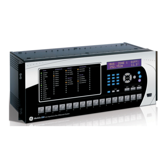
LED panel 2 LED panel 3 Display Front panel RS232 port Small user-programmable User-programmable Keypad (control) pushbuttons 1 to 7 pushbuttons 1 to 12 827801A7.CDR Figure 4–16: UR-SERIES STANDARD HORIZONTAL FACEPLATE PANELS GE Multilin B90 Low Impedance Bus Differential System 4-13... -
Page 100: Led Indicators
OTHER: This LED indicates a composite function was involved. • PHASE A: This LED indicates phase A was involved. • PHASE B: This LED indicates phase B was involved. • PHASE C: This LED indicates phase C was involved. 4-14 B90 Low Impedance Bus Differential System GE Multilin... - Page 101 VOLTAGE: Indicates voltage was involved. • CURRENT: Indicates current was involved. • FREQUENCY: Indicates frequency was involved. • OTHER: Indicates a composite function was involved. • PHASE A: Indicates phase A was involved. GE Multilin B90 Low Impedance Bus Differential System 4-15...
-
Page 102: Custom Labeling Of Leds
LEDs are fully user-programmable. The default labels can be replaced by user-printed labels for both panels as explained in the following section. SETTINGS IN USE 842783A1.CDR Figure 4–20: LED PANEL 2 (DEFAULT LABELS) 4.3.3 CUSTOM LABELING OF LEDS a) ENHANCED FACEPLATE The following procedure requires these pre-requisites: 4-16 B90 Low Impedance Bus Differential System GE Multilin... - Page 103 Remove the B90 label insert tool from the package and bend the tabs as described in the following procedures. These tabs are used for removal of the default and custom LED labels. It is important that the tool be used EXACTLY as shown below, with the printed side containing the GE part number facing the user.
- Page 104 The following procedure describes how to remove the LED labels from the B90 enhanced front panel and insert the custom labels. Use the knife to lift the LED label and slide the label tool underneath. Make sure the bent tabs are pointing away from the relay. 4-18 B90 Low Impedance Bus Differential System GE Multilin...
- Page 105 Slide the new LED label inside the pocket until the text is properly aligned with the LEDs, as shown below. The following procedure describes how to remove the user-programmable pushbutton labels from the B90 enhanced front panel and insert the custom labels. GE Multilin B90 Low Impedance Bus Differential System 4-19...
- Page 106 Slide the label tool under the user-programmable pushbutton label until the tabs snap out as shown below. This attaches the label tool to the user-programmable pushbutton label. Remove the tool and attached user-programmable pushbutton label as shown below. 4-20 B90 Low Impedance Bus Differential System GE Multilin...
- Page 107 The panel templates provide relative LED locations and located example text (x) edit boxes. The following procedure demonstrates how to install/uninstall the custom panel labeling. Remove the clear Lexan Front Cover (GE Multilin part number: 1501-0014). Push in...
-
Page 108: Display
Microsoft Word 97 or later software for editing the template • 1 each of: 8.5" x 11" white paper, exacto knife, ruler, custom display module (GE Multilin Part Number: 1516-0069), and a custom module cover (GE Multilin Part Number: 1502-0015) The following procedure describes how to customize the B90 display module: Open the LED panel customization template with Microsoft Word. - Page 109 TIME: 1.0 s To view the remaining settings associated with the Display Properties subheader, DEFAULT MESSAGE repeatedly press the MESSAGE DOWN key. The last message appears as shown. INTENSITY: 25% GE Multilin B90 Low Impedance Bus Differential System 4-23...
-
Page 110: Changing Settings
ENTERING ALPHANUMERIC TEXT Text settings have data values which are fixed in length, but user-defined in character. They can be upper case letters, lower case letters, numerals, and a selection of special characters. 4-24 B90 Low Impedance Bus Differential System GE Multilin... -
Page 111: Settings
When the "NEW SETTING HAS BEEN STORED" message appears, the relay is in "Programmed" state and the In Service LED turns on. e) ENTERING INITIAL PASSWORDS The B90 supports password entry from a local or remote connection. GE Multilin B90 Low Impedance Bus Differential System 4-25... - Page 112 FlexLogic operand is set to “On” and the B90 does not allow settings or command LOCAL ACCESS DENIED level access via the faceplate interface for the next five minutes, or in the event that an incorrect Command Or Setting 4-26 B90 Low Impedance Bus Differential System GE Multilin...
- Page 113 B90 does not allow Settings or Command access via the any external communications interface for the next ten minutes. FlexLogic operand is set to “Off” after the expiration of the ten-minute timeout. REMOTE ACCESS DENIED GE Multilin B90 Low Impedance Bus Differential System 4-27...
- Page 114 4.3 FACEPLATE INTERFACE 4 HUMAN INTERFACES 4-28 B90 Low Impedance Bus Differential System GE Multilin...
-
Page 115: Overview
SETTINGS AC INPUTS See page 5-69. SYSTEM SETUP POWER SYSTEM See page 5-70. FLEXCURVES See page 5-71. BUS See page 5-78. GE Multilin B90 Low Impedance Bus Differential System... - Page 116 VIRTUAL OUTPUTS See page 5-132. REMOTE INPUTS See page 5-134. REMOTE DPS INPUTS See page 5-135. REMOTE OUTPUTS See page 5-135. DNA BIT PAIRS B90 Low Impedance Bus Differential System GE Multilin...
-
Page 117: Introduction To Elements
VT ratio and connection) to secondary VT voltage applied to the relay. For example, on a system with a 13.8 kV nominal primary voltage and with 14400:120 V delta-connected VTs, the second- ary nominal voltage (1 pu) would be: GE Multilin B90 Low Impedance Bus Differential System... - Page 118 The DPO event is created when the measure and decide comparator output transits from the pickup state (logic 1) to the dropout state (logic 0). This could happen when the element is in the operate state if the reset delay time is not 0. B90 Low Impedance Bus Differential System GE Multilin...
-
Page 119: Product Setup
Test mode operation The command and setting passwords are defaulted to “0” when the relay is shipped from the factory. When a password is set to “0”, the password security feature is disabled. GE Multilin B90 Low Impedance Bus Differential System... - Page 120 If the password is correctly entered, access will be allowed. Accessibility automatically reverts to the “Restricted” level according to the access level timeout setting values. B90 Low Impedance Bus Differential System GE Multilin...
- Page 121 If a command or setting password is lost (or forgotten), consult the factory with the corresponding Encrypted Password value. If you establish a local connection to the relay (serial), you cannot view remote passcodes. NOTE GE Multilin B90 Low Impedance Bus Differential System...
- Page 122 Range: selected FlexLogic operands (see below) DUAL PERMISSION LOCAL SETTING AUTH: SECURITY ACCESS Range: FlexLogic operand REMOTE SETTING AUTH: MESSAGE Range: 5 to 480 minutes in steps of 1 ACCESS AUTH MESSAGE TIMEOUT: 30 min. B90 Low Impedance Bus Differential System GE Multilin...
-
Page 123: Cybersentry Security
Log in to the relay as Administrator by using the Value keys on the front panel to enter the default password "ChangeMe1#". The "Lock relay" setting needs to be disabled in the Security > Supervisory menu. Disabling this set- ting allows settings configuration and firmware upgrade. GE Multilin B90 Low Impedance Bus Differential System... - Page 124 Operator, Factory (for factory use only), None None Default: None CHANGE LOCAL See page 5–11. MESSAGE PASSWORDS SESSION See page 5–12. MESSAGE SETTINGS RESTORE DEFAULTS See page 5–12. MESSAGE 5-10 B90 Low Impedance Bus Differential System GE Multilin...
- Page 125 Observer role requires a password. • The default password is “ChangeMe1#”. • Once the passwords are set, the Administrator with Supervisor approval can change the role associated password. GE Multilin B90 Low Impedance Bus Differential System 5-11...
- Page 126 Range: Enable, Disable FACTORY SERVICE: MESSAGE MODE: Disable SELF TESTS See below MESSAGE Range: Enable, Disable SUPERVISOR ROLE: MESSAGE Disable Range: 1 to 9999 minutes SERIAL INACTIVITY MESSAGE TIMEOUT: 3 5-12 B90 Low Impedance Bus Differential System GE Multilin...
- Page 127 Example: If this setting is "Yes" and an attempt is made to change settings or upgrade the firmware, the UR device denies the setting changes and denies upgrading the firmware. If this setting is "No", the UR device accepts setting changes and firmware upgrade. This role is disabled by default. GE Multilin B90 Low Impedance Bus Differential System 5-13...
- Page 128 Settings Lock: If this setting is Enabled then an unauthorized write attempt to a setting for a given role activates this self test. PATH: SETTINGS PRODUCT SETUP SECURITY SUPERVISORY SELF TESTS FAILED AUTHENTICATE Range: Enabled, Disabled FAILED FAILED AUTHENTICATE AUTHENTICATE FUNCTION: Enabled 5-14 B90 Low Impedance Bus Differential System GE Multilin...
-
Page 129: Display Properties
The B90 applies a cut-off value to the magnitudes and angles of the measured voltages. If the magnitude is below the cut-off level, it is substituted with zero. This operation applies to phase and auxiliary voltages, and symmetrical GE Multilin B90 Low Impedance Bus Differential System... -
Page 130: Clear Relay Records
Set the properties for user-programmable pushbutton 1 by making the following changes in the SETTINGS PRODUCT menu: SETUP USER-PROGRAMMABLE PUSHBUTTONS USER PUSHBUTTON 1 “Self-reset” PUSHBUTTON 1 FUNCTION: “0.20 s” PUSHBTN 1 DROP-OUT TIME: 5-16 B90 Low Impedance Bus Differential System GE Multilin... -
Page 131: Communications
When using more than one Ethernet port, configure each to belong to a different network or subnet using the IP addresses and mask. Example 1 IP1/Mask1: 10.1.1.2/255.255.255.0 (where LAN 1 is 10.1.1.x/255.255.255.0) IP2/Mask2: 10.2.1.2/255.255.255.0 (where LAN2 is 10.2.1.x/255.255.255.0) GE Multilin B90 Low Impedance Bus Differential System 5-17... - Page 132 The topology shown in the following figure allows communications to SCADA, local configuration/monitoring through EnerVista, and access to the public network shared on the same LAN. No redundancy is provided. Figure 5–3: NETWORK CONFIGURATION FOR SINGLE LAN 5-18 B90 Low Impedance Bus Differential System GE Multilin...
- Page 133 LAN2, to which port 2 (P2) is connected and communications with SCADA on LAN3, to which port 3 (P3) is connected. There is no redundancy. Figure 5–5: MULTIPLE LANS, NO REDUNDANCY GE Multilin B90 Low Impedance Bus Differential System 5-19...
- Page 134 IP address. The client software (EnerVista UR Setup, for example) must be configured to use the correct port number if these settings are used. 5-20 B90 Low Impedance Bus Differential System GE Multilin...
- Page 135 Range: 0.001, 0.01. 0.1, 1, 10, 100, 1000, 10000, DNP CURRENT SCALE MESSAGE 100000 FACTOR: 1 Range: 0.001, 0.01. 0.1, 1, 10, 100, 1000, 10000, DNP VOLTAGE SCALE MESSAGE 100000 FACTOR: 1 GE Multilin B90 Low Impedance Bus Differential System 5-21...
- Page 136 Range: 0 to 32 in steps of 1 DNP NUMBER OF PAIRED MESSAGE CONTROL POINTS: 0 Range: 10 to 300 s in steps of 1 DNP TCP CONNECTION MESSAGE TIMEOUT: 120 s 5-22 B90 Low Impedance Bus Differential System GE Multilin...
- Page 137 B90 analog input data into the following types: current, voltage, power, energy, power factor, and other. Each setting represents the default deadband value for all analog input points of that type. For example, to trigger unsolic- GE Multilin B90 Low Impedance Bus Differential System...
- Page 138 256 points. The value for each point is user-programmable and can be configured by assigning FlexLogic operands for binary inputs / MSP points or FlexAnalog parameters for analog inputs / MME points. 5-24 B90 Low Impedance Bus Differential System GE Multilin...
- Page 139 60870-5-104 point lists must be in one continuous block, any points assigned after the first “Off” point are ignored. NOTE Changes to the DNP / IEC 60870-5-104 point lists will not take effect until the B90 is restarted. NOTE GE Multilin B90 Low Impedance Bus Differential System 5-25...
- Page 140 PATH: SETTINGS PRODUCT SETUP COMMUNICATIONS IEC 61850 PROTOCOL GSSE/GOOSE CONFIGURATION GSSE / GOOSE TRANSMISSION CONFIGURATION RECEPTION MESSAGE The main transmission menu is shown below: 5-26 B90 Low Impedance Bus Differential System GE Multilin...
- Page 141 IEC 61850 GSSE application ID name string sent as part of each GSSE message. This GSSE ID string identifies the GSSE message to the receiving device. In B90 releases previous to 5.0x, this name string was repre- sented by the setting. RELAY NAME GE Multilin B90 Low Impedance Bus Differential System 5-27...
- Page 142 ID for each GOOSE sending device. This value can be left at its default if the feature is not required. Both the GOOSE VLAN settings are required by IEC 61850. PRIORITY GOOSE ETYPE APPID 5-28 B90 Low Impedance Bus Differential System GE Multilin...
- Page 143 The aggressive scheme is only supported in fast type 1A GOOSE messages (GOOSEOut 1 and GOOSEOut 2). For slow GOOSE messages (GOOSEOut 3 to GOOSEOut 8) the aggressive scheme is the same as the medium scheme. GE Multilin B90 Low Impedance Bus Differential System...
- Page 144 Configure the transmission dataset. Configure the GOOSE service settings. Configure the data. The general steps required for reception configuration are: Configure the reception dataset. Configure the GOOSE service settings. Configure the data. 5-30 B90 Low Impedance Bus Differential System GE Multilin...
- Page 145 Configure the GOOSE service settings by making the following changes in the INPUTS/OUTPUTS REMOTE DEVICES settings menu: REMOTE DEVICE 1 – to match the GOOSE ID string for the transmitting device. Enter “GOOSEOut_1”. REMOTE DEVICE 1 ID GE Multilin B90 Low Impedance Bus Differential System 5-31...
- Page 146 The status value for GGIO1.ST.Ind1.stVal is determined by the FlexLogic operand assigned to GGIO1 indication 1. Changes to this operand will result in the transmission of GOOSE messages con- taining the defined dataset. 5-32 B90 Low Impedance Bus Differential System GE Multilin...
- Page 147 This conforms to the IEC 61850 standard. The is a LOCATION variable string and can be composed of ASCII characters. This string appears within the PhyName of the LPHD node. GE Multilin B90 Low Impedance Bus Differential System 5-33...
- Page 148 0.001%”. Thus, it is important to know the maximum value for each MMXU measured quantity, since this represents the 100.00% value for the deadband. 5-34 B90 Low Impedance Bus Differential System GE Multilin...
- Page 149 The GGIO2 control configuration settings are used to set the control model for each input. The available choices are “0” (status only), “1” (direct control), and “2” (SBO with normal security). The GGIO2 control points are used to control the B90 virtual inputs. GE Multilin B90 Low Impedance Bus Differential System 5-35...
- Page 150 ANALOG IN 1 MAX numbers. Because of the large range of these settings, not all values can be stored. Some values may be rounded to the closest possible floating point number. NOTE 5-36 B90 Low Impedance Bus Differential System GE Multilin...
- Page 151 Since GSSE/GOOSE messages are multicast Ethernet by specification, they will not usually be forwarded by net- work routers. However, GOOSE messages may be forwarded by routers if the router has been configured for VLAN functionality. NOTE GE Multilin B90 Low Impedance Bus Differential System 5-37...
- Page 152 MESSAGE THRESHOLD: 30000 Range: 0 to 65535 in steps of 1 IEC ENERGY DEFAULT MESSAGE THRESHOLD: 30000 Range: 0 to 65535 in steps of 1 IEC OTHER DEFAULT MESSAGE THRESHOLD: 30000 5-38 B90 Low Impedance Bus Differential System GE Multilin...
-
Page 153: Modbus User Map
Range: None, PP/IRIG-B/PTP/SNTP, IRIG-B/PP/PTP/ REAL TIME SYNCRONIZING SOURCE: SNTP, PP/PTP/IRIG-B/SNTP CLOCK None Range: Disabled, Enabled REAL TIME CLOCK MESSAGE EVENTS: Disabled Range: None, DC Shift, Amplitude Modulated IRIG-B SIGNAL TYPE: MESSAGE None GE Multilin B90 Low Impedance Bus Differential System 5-39... - Page 154 Range: 0 to 60 000 ns in steps of 1 PORT 1 PATH DELAY MESSAGE ADDER: 00000 ns Range: –1 000 to +1 000 ns in steps of 1 PORT 1 PATH DELAY MESSAGE ASYMMETRY: 0000 ns 5-40 B90 Low Impedance Bus Differential System GE Multilin...
- Page 155 Except in unusual cases, the two fibers are of essentially identical length and composition, so this setting should be set to zero. GE Multilin B90 Low Impedance Bus Differential System...
- Page 156 If the IRIG-B signal is removed, the time obtained from the SNTP server is used. If either SNTP or IRIG-B is enabled, the B90 clock value cannot be changed using the front panel keypad. 5-42 B90 Low Impedance Bus Differential System GE Multilin...
- Page 157 DAYLIGHT SAVINGS TIME (DST) Note that when IRIG-B time synchronization is active, the local time in the IRIG-B signal contains any daylight savings time offset and so the DST settings are ignored. GE Multilin B90 Low Impedance Bus Differential System 5-43...
-
Page 158: User-Programmable Fault Report
RMS, phase angle, frequency, temperature, etc., to be stored should the report be created. Up to 32 channels can be configured. Two reports are configurable to cope with variety of trip conditions and items of interest. 5-44 B90 Low Impedance Bus Differential System GE Multilin... -
Page 159: Oscillography
64 samples per cycle; that is, it has no effect on the fundamental calculations of the device. When changes are made to the oscillography settings, all existing oscillography records will be CLEARED. NOTE GE Multilin B90 Low Impedance Bus Differential System 5-45... - Page 160 - entering this number via the relay keypad will cause the corresponding parameter to be displayed. If there are no CT/VT modules and analog input modules, no analog traces will appear in the file; only the digital traces will appear. 5-46 B90 Low Impedance Bus Differential System GE Multilin...
-
Page 161: User-Programmable Leds
The test responds to the position and rising edges of the control input defined by the set- LED TEST CONTROL ting. The control pulses must last at least 250 ms to take effect. The following diagram explains how the test is executed. GE Multilin B90 Low Impedance Bus Differential System 5-47... - Page 162 2. Once stage 2 has started, the pushbutton can be released. When stage 2 is completed, stage 3 will automatically start. The test may be aborted at any time by pressing the pushbutton. 5-48 B90 Low Impedance Bus Differential System GE Multilin...
- Page 163 LED 19 operand LED 8 operand LED 20 operand LED 9 operand LED 21 operand LED 10 operand LED 22 operand LED 11 operand LED 23 operand LED 12 operand LED 24 operand GE Multilin B90 Low Impedance Bus Differential System 5-49...
-
Page 164: User-Programmable Self Tests
There are three standard control pushbuttons, labeled USER 1, USER 2, and USER 3, on the standard and enhanced front panels. These are user-programmable and can be used for various applications such as performing an LED test, switching setting groups, and invoking and scrolling though user-programmable displays. 5-50 B90 Low Impedance Bus Differential System GE Multilin... - Page 165 BREAKERS/BREAKER 1/ BREAKER 1 PUSHBUTTON CONTROL Enabled=1 TIMER FLEXLOGIC OPERAND SYSTEM SETUP/ BREAKERS/BREAKER 2/ CONTROL PUSHBTN 1 ON 100 msec BREAKER 2 PUSHBUTTON CONTROL 842010A2.CDR Enabled=1 Figure 5–9: CONTROL PUSHBUTTON LOGIC GE Multilin B90 Low Impedance Bus Differential System 5-51...
-
Page 166: User-Programmable Pushbuttons
FlexLogic equations, protection elements, and control elements. Typical applications include breaker control, autorecloser blocking, and setting groups changes. The user-programmable pushbuttons are under the control level of password protection. The user-configurable pushbuttons for the enhanced faceplate are shown below. 5-52 B90 Low Impedance Bus Differential System GE Multilin... - Page 167 The pulse duration of the remote set, remote reset, or local pushbutton must be at least 50 ms to operate the push- button. This allows the user-programmable pushbuttons to properly operate during power cycling events and vari- ous system disturbances that may cause transient assertion of the operating signals. NOTE GE Multilin B90 Low Impedance Bus Differential System 5-53...
- Page 168 PUSHBTN 1 RESET • PUSHBTN 1 LOCAL: This setting assigns the FlexLogic operand serving to inhibit pushbutton operation from the front panel pushbuttons. This locking functionality is not applicable to pushbutton autoreset. 5-54 B90 Low Impedance Bus Differential System GE Multilin...
- Page 169 “High Priority” or “Normal”. PUSHBTN 1 MESSAGE • PUSHBUTTON 1 EVENTS: If this setting is enabled, each pushbutton state change will be logged as an event into event recorder. GE Multilin B90 Low Impedance Bus Differential System 5-55...
- Page 170 SETTING SETTING Autoreset Delay Autoreset Function = Enabled = Disabled SETTING Drop-Out Timer TIMER FLEXLOGIC OPERAND 200 ms PUSHBUTTON 1 ON 842021A3.CDR Figure 5–12: USER-PROGRAMMABLE PUSHBUTTON LOGIC (Sheet 1 of 2) 5-56 B90 Low Impedance Bus Differential System GE Multilin...
-
Page 171: Flex State Parameters
PRODUCT SETUP FLEX STATE PARAMETERS Range: FlexLogic operand FLEX STATE PARAMETER PARAMETERS Range: FlexLogic operand PARAMETER MESSAGE Range: FlexLogic operand PARAMETER MESSAGE Range: FlexLogic operand PARAMETER 256: MESSAGE GE Multilin B90 Low Impedance Bus Differential System 5-57... -
Page 172: User-Definable Displays
INVOKE AND SCROLL play, not at the first user-defined display. The pulses must last for at least 250 ms to take effect. INVOKE AND SCROLL 5-58 B90 Low Impedance Bus Differential System GE Multilin... - Page 173 While viewing a user display, press the ENTER key and then select the ‘Yes” option to remove the display from the user display list. Use the MENU key again to exit the user displays menu. GE Multilin B90 Low Impedance Bus Differential System...
- Page 174 MESSAGE CRC ALARM CH2 See page 5–66. MESSAGE UNRETURNED See page 5–67. MESSAGE MESSAGES ALARM CH1 UNRETURNED See page 5–67. MESSAGE MESSAGES ALARM CH2 5-60 B90 Low Impedance Bus Differential System GE Multilin...
-
Page 175: Direct Inputs And Outputs
0.2 of a power system cycle at 128 kbps and 0.4 of a power system cycle at 64 kbps, per each ‘bridge’. For B90 applications, the should be set to 128 kbps. DIRECT I/O DATA RATE GE Multilin B90 Low Impedance Bus Differential System 5-61... - Page 176 The following application examples illustrate the basic concepts for direct input and output configuration. Please refer to the Inputs and outputs section in this chapter for information on configuring FlexLogic operands (flags, bits) to be exchanged. 5-62 B90 Low Impedance Bus Differential System GE Multilin...
- Page 177 BLOCK UR IED 4 UR IED 2 UR IED 3 842712A1.CDR Figure 5–15: SAMPLE INTERLOCKING BUSBAR PROTECTION SCHEME For increased reliability, a dual-ring configuration (shown below) is recommended for this application. GE Multilin B90 Low Impedance Bus Differential System 5-63...
- Page 178 The complete application requires addressing a number of issues such as failure of both the communications rings, failure or out-of-service conditions of one of the relays, etc. Self-monitoring flags of the direct inputs and outputs feature would be primarily used to address these concerns. 5-64 B90 Low Impedance Bus Differential System GE Multilin...
- Page 179 Inputs and outputs section. A blocking pilot-aided scheme should be implemented with more security and, ideally, faster message delivery time. This could be accomplished using a dual-ring configuration as shown below. GE Multilin B90 Low Impedance Bus Differential System...
- Page 180 FlexLogic operand is set. When the total message counter reaches the user-defined maximum specified by the set- CRC ALARM CH1 MESSAGE COUNT ting, both the counters reset and the monitoring process is restarted. 5-66 B90 Low Impedance Bus Differential System GE Multilin...
- Page 181 The unreturned messages alarm function is available on a per-channel basis and is active only in the ring configuration. The total number of unreturned input and output messages is available as the ACTUAL VALUES STATUS DIRECT actual value. INPUTS UNRETURNED MSG COUNT CH1 GE Multilin B90 Low Impedance Bus Differential System 5-67...
-
Page 182: Installation
"Programmed" state. UNIT NOT PROGRAMMED setting allows the user to uniquely identify a relay. This name will appear on generated reports. RELAY NAME 5-68 B90 Low Impedance Bus Differential System GE Multilin... -
Page 183: System Setup
F8F and L8K modules displays the following voltage inputs: F5, F6, F7, F8, and L8. The nominal setting is the voltage across the relay input terminals when nominal voltage is VT F1 SECONDARY applied to the VT primary. NOTE GE Multilin B90 Low Impedance Bus Differential System 5-69... -
Page 184: Power System
UR-series relays provided the relays have an IRIG-B connection. should only be set to "Disabled" in very unusual circumstances; consult the factory for spe- FREQUENCY TRACKING cial variable-frequency applications. NOTE 5-70 B90 Low Impedance Bus Differential System GE Multilin... -
Page 185: Flexcurves
1.03 pu. It is recommended to set the two times to a similar value; otherwise, the linear approximation may result in NOTE undesired behavior for the operating quantity that is close to 1.00 pu. GE Multilin B90 Low Impedance Bus Differential System 5-71... - Page 186 The multiplier and adder settings only affect the curve portion of the characteristic and not the MRT and HCT set- tings. The HCT settings override the MRT settings for multiples of pickup greater than the HCT ratio. NOTE 5-72 B90 Low Impedance Bus Differential System GE Multilin...
- Page 187 EnerVista UR Setup software generates an error message and discards the proposed changes. NOTE e) STANDARD RECLOSER CURVES The standard recloser curves available for the B90 are displayed in the following graphs. GE Multilin B90 Low Impedance Bus Differential System 5-73...
- Page 188 Figure 5–23: RECLOSER CURVES GE101 TO GE106 GE142 GE138 GE120 GE113 0.05 7 8 9 10 12 CURRENT (multiple of pickup) 842725A1.CDR Figure 5–24: RECLOSER CURVES GE113, GE120, GE138 AND GE142 5-74 B90 Low Impedance Bus Differential System GE Multilin...
- Page 189 Figure 5–25: RECLOSER CURVES GE134, GE137, GE140, GE151 AND GE201 GE152 GE141 GE131 GE200 7 8 9 10 12 CURRENT (multiple of pickup) 842728A1.CDR Figure 5–26: RECLOSER CURVES GE131, GE141, GE152, AND GE200 GE Multilin B90 Low Impedance Bus Differential System 5-75...
- Page 190 Figure 5–27: RECLOSER CURVES GE133, GE161, GE162, GE163, GE164 AND GE165 GE132 GE139 GE136 GE116 0.05 GE117 GE118 0.02 0.01 7 8 9 10 12 CURRENT (multiple of pickup) 842726A1.CDR Figure 5–28: RECLOSER CURVES GE116, GE117, GE118, GE132, GE136, AND GE139 5-76 B90 Low Impedance Bus Differential System GE Multilin...
- Page 191 Figure 5–29: RECLOSER CURVES GE107, GE111, GE112, GE114, GE115, GE121, AND GE122 GE202 GE135 GE119 7 8 9 10 12 CURRENT (multiple of pickup) 842727A1.CDR Figure 5–30: RECLOSER CURVES GE119, GE135, AND GE202 GE Multilin B90 Low Impedance Bus Differential System 5-77...
-
Page 192: Bus
BUS 2D CT = F8 BUS 1D DIRECTION = IN BUS 2D DIRECTION = IN BUS 1E CT = F5 BUS 1E DIRECTION = OUT 836757A2.CDR Figure 5–31: BUS ZONE DIRECTION SETTING 5-78 B90 Low Impedance Bus Differential System GE Multilin... - Page 193 CT. Refer to the chapter 9 for more details on configuring bus differential zones. GE Multilin B90 Low Impedance Bus Differential System...
-
Page 194: Flexlogic
Traditionally, protective relay logic has been relatively limited. Any unusual applications involving interlocks, blocking, or supervisory functions had to be hard-wired using contact inputs and outputs. FlexLogic minimizes the requirement for aux- iliary components and wiring while making more complex schemes possible. 5-80 B90 Low Impedance Bus Differential System GE Multilin... - Page 195 The virtual input is presently in the ON state. Virtual Output Virt Op 1 On The virtual output is presently in the set state (i.e. evaluation of the equation which produces this virtual output results in a "1"). GE Multilin B90 Low Impedance Bus Differential System 5-81...
- Page 196 ISOLATOR 1 BLOCK Blocking signal for substation switching operations set due to contact discrepancy of isolator 1 (acknowledgeable) ISOLATOR 2 to ISOLATOR 48 Same set of operands as shown for ISOLATOR 1 5-82 B90 Low Impedance Bus Differential System GE Multilin...
- Page 197 Asserted while the remote double-point status input is off. RemDPS Ip 1 ON Asserted while the remote double-point status input is on. REMDPS Ip 2... Same set of operands as per REMDPS 1 above GE Multilin B90 Low Impedance Bus Differential System 5-83...
- Page 198 Communications source of the reset command. RESET OP (OPERAND) Operand (assigned in the menu) source INPUTS/OUTPUTS RESETTING of the reset command. RESET OP (PUSHBUTTON) Reset key (pushbutton) source of the reset command. 5-84 B90 Low Impedance Bus Differential System GE Multilin...
- Page 199 ‘1’ 2 to 16 all inputs are ‘1’ 2 to 16 all inputs are ‘0’ NAND 2 to 16 any input is ‘0’ only one input is ‘1’ GE Multilin B90 Low Impedance Bus Differential System 5-85...
-
Page 200: Flexlogic Rules
When making changes to settings, all FlexLogic equations are re-compiled whenever any new setting value is entered, so all latches are automatically reset. If it is necessary to re-initialize FlexLogic during testing, for example, it is suggested to power the unit down and then back up. 5-86 B90 Low Impedance Bus Differential System GE Multilin... -
Page 201: Flexlogic Example
Dropout State=Pickup (200 ms) DIGITAL ELEMENT 2 Timer 1 State=Operated Time Delay on Pickup (800 ms) CONTACT INPUT H1c State=Closed VIRTUAL OUTPUT 3 827026A2.VSD Figure 5–35: LOGIC EXAMPLE WITH VIRTUAL OUTPUTS GE Multilin B90 Low Impedance Bus Differential System 5-87... - Page 202 Following the procedure outlined, start with parameter 99, as follows: 99: The final output of the equation is virtual output 3, which is created by the operator "= Virt Op n". This parameter is therefore "= Virt Op 3." 5-88 B90 Low Impedance Bus Differential System GE Multilin...
- Page 203 87: The input just below the upper input to OR #1 is operand “Virt Op 2 On". 86: The upper input to OR #1 is operand “Virt Op 1 On". 85: The last parameter is used to set the latch, and is operand “Virt Op 4 On". GE Multilin B90 Low Impedance Bus Differential System 5-89...
- Page 204 In the following equation, virtual output 3 is used as an input to both latch 1 and timer 1 as arranged in the order shown below: DIG ELEM 2 OP Cont Ip H1c On AND(2) 5-90 B90 Low Impedance Bus Differential System GE Multilin...
-
Page 205: Flexlogic Equation Editor
TIMER 1 TYPE: This setting is used to select the time measuring unit. • TIMER 1 PICKUP DELAY: Sets the time delay to pickup. If a pickup delay is not required, set this function to "0". GE Multilin B90 Low Impedance Bus Differential System 5-91... -
Page 206: Non-Volatile Latches
LATCH 1 ON Dominant LATCH 1 OFF SETTING Previous Previous State State LATCH 1 SET: Off=0 RESET 842005A1.CDR Figure 5–41: NON-VOLATILE LATCH OPERATION TABLE (N = 1 to 16) AND LOGIC 5-92 B90 Low Impedance Bus Differential System GE Multilin... -
Page 207: Grouped Elements
Each of the six setting group menus is identical. Setting group 1 (the default active group) automatically becomes active if no other group is active (see Section 5.6.3: Setting Groups on page 5–119 for further details). GE Multilin B90 Low Impedance Bus Differential System... - Page 208 The biased bus differential function has a dual-slope operating characteristic (see figure below) operating in conjunction with saturation detection and a directional comparison principle (refer to the Bus zone 1 differential scheme logic figure in this section). 5-94 B90 Low Impedance Bus Differential System GE Multilin...
- Page 209 CTs operating in their linear mode, i.e. in load conditions and during distant external faults. When adjusting this setting, it must be kept in mind that the restraining signal used by the biased bus differential protection element is created as the maximum of all the input currents. GE Multilin B90 Low Impedance Bus Differential System 5-95...
- Page 210 BF function to isolate the entire zone of busbar protection. More information on the bus zone differential settings can be found in the Application of settings chapter. 5-96 B90 Low Impedance Bus Differential System GE Multilin...
- Page 211 5 SETTINGS 5.5 GROUPED ELEMENTS Figure 5–43: BUS ZONE 1 DIFFERENTIAL SCHEME LOGIC GE Multilin B90 Low Impedance Bus Differential System 5-97...
- Page 212 Range: Yes, No BF1 USE TIMER 2: MESSAGE Range: 0.000 to 65.535 s in steps of 0.001 BF1 TIMER 2 PICKUP MESSAGE DELAY: 0.000 s Range: Yes, No BF1 USE TIMER 3: MESSAGE 5-98 B90 Low Impedance Bus Differential System GE Multilin...
- Page 213 Range: Enabled, Disabled BF1 EVENTS: MESSAGE Disabled BREAKER FAILURE CURRENT SUPV 2 BREAKER FAILURE 2 BREAKER FAILURE CURRENT SUPV 24 BREAKER FAILURE 24 GE Multilin B90 Low Impedance Bus Differential System 5-99...
- Page 214 This mode is typically used during maintenance. There is no current level check for this stage since this is associated with small currents. Timer 3 is typically set with a longer time. 5-100 B90 Low Impedance Bus Differential System GE Multilin...
- Page 215 BF1 TRIP DROPOUT TIME DELAY: This setting is used to set the period of time for which the trip output is sealed-in. This timer must be coordinated with the automatic reclosing scheme of the failed breaker, to which the breaker failure GE Multilin B90 Low Impedance Bus Differential System...
- Page 216 BF1 AMP LOSET PICKUP: This setting is used to set the phase current fault detection level. Generally this setting should detect the lowest expected fault current on the protected breaker, after a breaker opening resistor is inserted approximately 90% of resistor current). Figure 5–44: BREAKER FAILURE CURRENT SUPERVISION LOGIC 5-102 B90 Low Impedance Bus Differential System GE Multilin...
- Page 217 5 SETTINGS 5.5 GROUPED ELEMENTS Figure 5–45: BREAKER FAILURE LOGIC GE Multilin B90 Low Impedance Bus Differential System 5-103...
- Page 218 DIRECT INPUT 6 BIT NUMBER : "3" (message received from IED 3) DIRECT INPUT 7 DEVICE : "13" (this is BKRSUPV 3 SUPV OP for Phase C) DIRECT INPUT 7 BIT NUMBER 5-104 B90 Low Impedance Bus Differential System GE Multilin...
- Page 219 The relay uses sophisticated algorithms to speed up the reset time of the breaker failure overcurrent supervision. Caution must be paid when testing the B90 for BF reset times. In particular, the current must be interrupted in a way NOTE resembling the actual breaker operation (zero-crossing). GE Multilin B90 Low Impedance Bus Differential System 5-105...
- Page 220 This setting discriminates between undervoltage conditions for energized and de-energized circuits. If the element is used for low-voltage supervision, set this value to zero. 5-106 B90 Low Impedance Bus Differential System GE Multilin...
- Page 221 See page 5-112. MESSAGE OVERCURRENT 24 TIME See page 5-113. MESSAGE OVERCURRENT TIME See page 5-113. MESSAGE OVERCURRENT TIME See page 5-113. MESSAGE OVERCURRENT 24 GE Multilin B90 Low Impedance Bus Differential System 5-107...
- Page 222 5 SETTINGS b) INVERSE TOC CURVE CHARACTERISTICS The inverse time overcurrent curves used by the time overcurrent elements are the IEEE, IEC, GE Type IAC, and I t stan- dard curve shapes. This allows for simplified coordination with downstream devices.
- Page 223 38.634 22.819 14.593 11.675 10.130 9.153 8.470 7.960 7.562 7.241 51.512 30.426 19.458 15.567 13.507 12.204 11.294 10.614 10.083 9.654 10.0 64.390 38.032 24.322 19.458 16.883 15.255 14.117 13.267 12.604 12.068 GE Multilin B90 Low Impedance Bus Differential System 5-109...
- Page 224 1.067 0.668 0.526 0.451 0.404 0.371 0.346 0.327 0.311 0.80 2.446 1.423 0.890 0.702 0.602 0.538 0.494 0.461 0.435 0.415 1.00 3.058 1.778 1.113 0.877 0.752 0.673 0.618 0.576 0.544 0.518 5-110 B90 Low Impedance Bus Differential System GE Multilin...
- Page 225 = characteristic constant, and T = reset time in seconds (assuming energy capacity is 100% RESET is “Timed”) RESET Table 5–15: GE TYPE IAC INVERSE TIME CURVE CONSTANTS IAC CURVE SHAPE IAC Extreme Inverse 0.0040 0.6379 0.6200 1.7872 0.2461...
- Page 226 Range: 0.000 to 65.535 s in steps of 0.001 IOC1 RESET DELAY: MESSAGE 0.000 s Range: FlexLogic™ operand IOC1 BLOCK: MESSAGE Range: Self-Reset, Latched, Disabled IOC1 TARGET: MESSAGE Self-Reset Range: Enabled, Disabled IOC1 EVENTS: MESSAGE Disabled 5-112 B90 Low Impedance Bus Differential System GE Multilin...
- Page 227 TOC1 TD MULTIPLIER: MESSAGE 1.00 Range: Instantaneous, Timed TOC1 RESET: MESSAGE Instantaneous Range: FlexLogic™ operand TOC1 BLOCK: MESSAGE Range: Self-Reset, Latched, Disabled TOC1 TARGET: MESSAGE Self-Reset Range: Enabled, Disabled TOC1 EVENTS: MESSAGE Disabled GE Multilin B90 Low Impedance Bus Differential System 5-113...
- Page 228 The End Fault Protection (EFP) element operates for dead-zone faults; i.e., faults between the CT and an open feeder breaker. Since a bus protection zone terminates on the CTs, faults between the CT and breaker require special consider- ation. 5-114 B90 Low Impedance Bus Differential System GE Multilin...
- Page 229 Therefore, the close status of the isolator shall be used as the block setting. BUS SECTION TRANSFER BUS selective "dead-zone" only if the isolator is open Figure 5–52: END FAULT PROTECTION AND BY-PASS ISOLATORS GE Multilin B90 Low Impedance Bus Differential System 5-115...
- Page 230 Off = 0 EFP 1 OP SETTINGS EFP 1 DPO SETTING EFP 1 BRK DELAY: EFP PKP EFP 1 BREAKER OPEN: Off = 0 836004A1.vsd Figure 5–53: END FAULT PROTECTION LOGIC 5-116 B90 Low Impedance Bus Differential System GE Multilin...
-
Page 231: Control Elements
If more than one operate-type operand is required, it may be assigned directly from the trip bus menu. GE Multilin B90 Low Impedance Bus Differential System... - Page 232 = Enabled TRIP BUS 1 BLOCK = Off SETTINGS TRIP BUS 1 LATCHING = Enabled TRIP BUS 1 RESET = Off FLEXLOGIC OPERAND RESET OP 842023A1.CDR Figure 5–55: TRIP BUS LOGIC 5-118 B90 Low Impedance Bus Differential System GE Multilin...
-
Page 233: Setting Groups
SETTING GROUP 1 NAME SETTING GROUP 6 NAME groups. Once programmed, this name will appear on the second line of the GROUPED ELEMENTS SETTING GROUP 1(6) menu display. GE Multilin B90 Low Impedance Bus Differential System 5-119... -
Page 234: Digital Elements
Some versions of the digital input modules include an active voltage monitor circuit connected across form-A contacts. The voltage monitor circuit limits the trickle current through the output circuit (see technical specifications for form-A). 5-120 B90 Low Impedance Bus Differential System GE Multilin... - Page 235 The settings to use digital element 1 to monitor the breaker trip circuit are indicated below (EnerVista UR Setup example shown): The PICKUP DELAY setting should be greater than the operating time of the breaker to avoid nuisance alarms. NOTE GE Multilin B90 Low Impedance Bus Differential System 5-121...
- Page 236 “Off”. In this case, the settings are as follows (EnerVista UR Setup example shown). Figure 5–58: TRIP CIRCUIT EXAMPLE 2 The wiring connection for two examples above is applicable to both form-A contacts with voltage monitoring and solid-state contact with voltage monitoring. NOTE 5-122 B90 Low Impedance Bus Differential System GE Multilin...
-
Page 237: Monitoring Elements
CT Trouble is declared for the given phase by setting the appropriate FlexLogic output operand. The operand may be configured to raise an alarm and block the bus differential function for the corresponding zone of protection. GE Multilin B90 Low Impedance Bus Differential System... - Page 238 Bus protection zone discrimination depends heavily on reliable isolator position feedback. Therefore, two isolator auxiliary contacts – normally open and normally closed – must confirm the status of the isolator via the B90 contact inputs. 5-124 B90 Low Impedance Bus Differential System GE Multilin...
- Page 239 ISOLATOR 1 ALARM DELAY: This setting specifies a time delay after which an isolator alarm is issued by asserting the operand assigned to . The delay shall be longer than the slowest operation (transition) time of ISOLATOR 1 ALARM the isolator. GE Multilin B90 Low Impedance Bus Differential System 5-125...
- Page 240 ISOLATOR 1 BLOCK delay isolator position valid alarm ISOLATOR 1 ALARM acknowledged alarm acknowledging ISOLATOR 1 RESET signal 836744A1.vsd Figure 5–62: ISOLATOR MONITORING SAMPLE TIMING DIAGRAM 5-126 B90 Low Impedance Bus Differential System GE Multilin...
-
Page 241: Inputs/Outputs
The update is performed at the beginning of the protection pass so all protection and control functions, as well as FlexLogic equations, are fed with the updated states of the contact inputs. GE Multilin B90 Low Impedance Bus Differential System... - Page 242 "Breaker Closed (52b)" CONTACT INPUT H5A ID: "Enabled" CONTACT INPUT H5A EVENTS: Note that the 52b contact is closed when the breaker is open and open when the breaker is closed. 5-128 B90 Low Impedance Bus Differential System GE Multilin...
-
Page 243: 5Virtual Inputs
“Virtual Input 1 to OFF = 0” VIRTUAL INPUT 1 ID: (Flexlogic Operand) SETTING Virt Ip 1 VIRTUAL INPUT 1 TYPE: Latched Self - Reset 827080A2.CDR Figure 5–64: VIRTUAL INPUTS SCHEME LOGIC GE Multilin B90 Low Impedance Bus Differential System 5-129... -
Page 244: Contact Outputs
L-Cont Op 1 Range: FlexLogic operand OUTPUT H1a OPERATE: MESSAGE Range: FlexLogic operand OUTPUT H1a RESET: MESSAGE Range: Operate-dominant, Reset-dominant OUTPUT H1a TYPE: MESSAGE Operate-dominant Range: Disabled, Enabled OUTPUT H1a EVENTS: MESSAGE Disabled 5-130 B90 Low Impedance Bus Differential System GE Multilin... - Page 245 Application Example 3: A make before break functionality must be added to the preceding example. An overlap of 20 ms is required to implement this functionality as described below: GE Multilin B90 Low Impedance Bus Differential System 5-131...
-
Page 246: Virtual Outputs
Logic equations. Any change of state of a virtual output can be logged as an event if programmed to do so. For example, if Virtual Output 1 is the trip signal from FlexLogic and the trip relay is used to signal events, the settings would be programmed as follows: 5-132 B90 Low Impedance Bus Differential System GE Multilin... -
Page 247: Remote Devices
PRODUCT SETUP COMMUNICATIONS IEC 61850 PROTOCOL GSSE/GOOSE setting. CONFIGURATION TRANSMISSION GSSE GSSE ID In B90 releases previous to 5.0x, these name strings were represented by the setting. RELAY NAME GE Multilin B90 Low Impedance Bus Differential System 5-133... -
Page 248: Remote Inputs
0. When communication resumes, the input becomes fully operational. For additional information on GSSE/GOOOSE messaging, refer to the Remote Devices section in this chapter. NOTE 5-134 B90 Low Impedance Bus Differential System GE Multilin... -
Page 249: Remote Double-Point Status Inputs
The above operand setting represents a specific DNA function (as shown in the following table) to be transmitted. Table 5–19: IEC 61850 DNA ASSIGNMENTS IEC 61850 DEFINITION FLEXLOGIC OPERAND Test IEC 61850 TEST MODE ConfRev IEC 61850 CONF REV GE Multilin B90 Low Impedance Bus Differential System 5-135... -
Page 250: Resetting
DEVICE ID: 1 Range: 1 to 96 DIRECT INPUT MESSAGE BIT NUMBER: Range: On, Off, Latest/On, Latest/Off DIRECT INPUT MESSAGE DEFAULT STATE: Off Range: Enabled, Disabled DIRECT INPUT MESSAGE EVENTS: Disabled 5-136 B90 Low Impedance Bus Differential System GE Multilin... - Page 251 12 are used, as an example): UR IED 1: = “2” UR IED 2: = “Cont Ip 1 On” DIRECT INPUT 5 DEVICE ID DIRECT OUT 12 OPERAND = “12” DIRECT INPUT 5 BIT NUMBER GE Multilin B90 Low Impedance Bus Differential System 5-137...
- Page 252 . Upon losing communications or a device, the scheme is inclined to block (if any default state is set to “On”), or to trip the bus on any overcurrent condition (all default states set to “Off”). 5-138 B90 Low Impedance Bus Differential System GE Multilin...
- Page 253 " (forward a message from 1 to 3) DIRECT OUT 3 OPERAND: DIRECT INPUT 5 " " (forward a message from 3 to 1) DIRECT OUT 4 OPERAND: DIRECT INPUT 6 GE Multilin B90 Low Impedance Bus Differential System 5-139...
-
Page 254: Iec 61850 Goose Analogs
Table 5–20: GOOSE ANALOG INPUT BASE UNITS (Sheet 1 of 2) ELEMENT BASE UNITS dcmA BASE = maximum value of the DCMA INPUT MAX setting for the two transducers configured under the +IN and –IN inputs. FREQUENCY = 1 Hz BASE 5-140 B90 Low Impedance Bus Differential System GE Multilin... -
Page 255: Iec 61850 Goose Integers
“Default Value”, then the value of the GOOSE uinteger input is defined by the setting. UINTEGER 1 DEFAULT The GOOSE integer input FlexInteger values are available for use in other B90 functions that use FlexInteger values. GE Multilin B90 Low Impedance Bus Differential System 5-141... -
Page 256: Testing
The test mode state is indicated on the relay faceplate by a combination of the Test Mode LED indicator, the In-Service LED indicator, and by the critical fail relay, as shown in the following table. 5-142 B90 Low Impedance Bus Differential System GE Multilin... -
Page 257: Force Contact Inputs
Mode LED will be on, indicating that the relay is in test mode. The state of each contact input may be programmed as “Dis- abled”, “Open”, or “Closed”. All contact input operations return to normal when all settings for this feature are disabled. GE Multilin B90 Low Impedance Bus Differential System... -
Page 258: Force Contact Outputs
PUSHBUTTON 1 FUNCTION input 1 to initiate the Test mode, make the following changes in the menu: SETTINGS TESTING TEST MODE “Enabled” and “ ” TEST MODE FUNCTION: TEST MODE INITIATE: 5-144 B90 Low Impedance Bus Differential System GE Multilin... -
Page 259: Actual Values
See page 6-9. METERING CURRENTS See page 6-10. VOLTAGES See page 6-10. FREQUENCY See page 6-10. IEC 61850 See page 6-11. GOOSE ANALOGS GE Multilin B90 Low Impedance Bus Differential System... - Page 260 EVENT RECORDS See page 6-12. OSCILLOGRAPHY See page 6-12. ACTUAL VALUES MODEL INFORMATION See page 6-13. PRODUCT INFO FIRMWARE REVISIONS See page 6-13. B90 Low Impedance Bus Differential System GE Multilin...
-
Page 261: Contact Inputs
The state displayed will be that of the remote point unless the remote device has been established to be “Offline” in which case the value shown is the programmed default state for the remote input. GE Multilin B90 Low Impedance Bus Differential System... -
Page 262: Remote Double-Point Status Inputs
For example, ‘Virt Op 1’ refers to the virtual output in terms of the default name-array index. The second line of the display indicates the logic state of the virtual output, as calculated by the FlexLogic™ equation for that output. B90 Low Impedance Bus Differential System GE Multilin... -
Page 263: Remote Devices
Range: Off, On PARAM 2: Off MESSAGE Range: Off, On PARAM 256: Off MESSAGE There are 256 FlexState bits available. The second line value indicates the state of the given FlexState bit. GE Multilin B90 Low Impedance Bus Differential System... -
Page 264: Ethernet
CALIBRATING • if the port is synchronized, but the peer delay mechanism is non-operational, and SYNCH’D (NO PDELAY) • if synchronized. SYNCHRONIZED B90 Low Impedance Bus Differential System GE Multilin... -
Page 265: Iec 61850 Goose Integers
CH1: 0 AVG MSG RETURN MESSAGE TIME CH2: 0 ms UNRETURNED MSG MESSAGE COUNT CH2: 0 CRC FAIL COUNT MESSAGE CH2: 0 DIRECT INPUT MESSAGE DIRECT INPUT MESSAGE DIRECT INPUT 96: MESSAGE GE Multilin B90 Low Impedance Bus Differential System... -
Page 266: Direct Devices Status
Range: 0 to 4 MODBUS TCP (max 4) MESSAGE Range: 0 to 2 DNP (max 2) MESSAGE Range: 0 to 2 IEC-104 (max 2) MESSAGE Range: 0 to 4 PMU TCP (max 4) MESSAGE B90 Low Impedance Bus Differential System GE Multilin... -
Page 267: Metering Conventions
CT errors may impose significant unaccounted differential current. It is advisable to set the minimum pickup for 87B protection greater than the maximum differen- tial current during normal load conditions. GE Multilin B90 Low Impedance Bus Differential System... -
Page 268: Currents
FREQUENCY AND PHASE REFERENCE SETTINGS menu. Refer to the Power System section of chapter 5 for additional details. SYSTEM SETUP POWER SYSTEM 6-10 B90 Low Impedance Bus Differential System GE Multilin... -
Page 269: Iec 61580 Goose Analog Values
2 for additional details. The IEC 61850 GGIO3 analog input data points are displayed in this menu. The GGIO3 analog data values are received via IEC 61850 GOOSE messages sent from other devices. GE Multilin B90 Low Impedance Bus Differential System 6-11... -
Page 270: Records
A trigger can be forced here at any time by setting “Yes” to the command. Refer to the FORCE TRIGGER? COMMANDS menu for information on clearing the oscillography records. CLEAR RECORDS 6-12 B90 Low Impedance Bus Differential System GE Multilin... -
Page 271: Product Information
6.5PRODUCT INFORMATION 6.5.1 MODEL INFORMATION PATH: ACTUAL VALUES PRODUCT INFO MODEL INFORMATION Range: standard GE Multilin order code format; MODEL INFORMATION ORDER CODE LINE 1: example order code shown B90-E00-HCL-F8H-H6A Range: standard GE Multilin order code format... - Page 272 6.5 PRODUCT INFORMATION 6 ACTUAL VALUES 6-14 B90 Low Impedance Bus Differential System GE Multilin...
-
Page 273: Commands And Targets
The states of up to 64 virtual inputs are changed here. The first line of the display indicates the ID of the virtual input. The second line indicates the current or selected status of the virtual input. This status will be a state off (logic 0) or on (logic 1). GE Multilin B90 Low Impedance Bus Differential System... - Page 274 The complete date, as a minimum, must be entered to allow execution of this command. The new time (if entered) and date will take effect at the moment the ENTER key is clicked. The timescale of the entered time should be local time, including daylight time where and when applicable. B90 Low Impedance Bus Differential System GE Multilin...
-
Page 275: Relay Maintenance
CLEAR SECURITY DATA: Default: No With the CyberSentry option, this setting is available to enable or disable the following commands: • Administrator Logoff: Selecting ‘Yes’ allows the Supervisor to forcefully logoff an administrator session. GE Multilin B90 Low Impedance Bus Differential System... - Page 276 Operator Logoff: Selecting ‘Yes’ allows the Supervisor to forcefully logoff an operator session. • Clear Security Data: Selecting ‘Yes’ allows the Supervisor to forcefully clear all the security logs and clears all the operands associated with the self-tests. B90 Low Impedance Bus Differential System GE Multilin...
-
Page 277: Targets Menu
The critical fail relay on the power supply module is de-energized. • All other output relays are de-energized and are prevented from further operation. • The faceplate In Service LED indicator is turned off. • event is recorded. RELAY OUT OF SERVICE GE Multilin B90 Low Impedance Bus Differential System... - Page 278 How often the test is performed: On power up and whenever the PRODUCT SETUP INSTALLATION RELAY SETTINGS setting is altered • What to do: Program all settings and then set to “Programmed”. PRODUCT SETUP INSTALLATION RELAY SETTINGS B90 Low Impedance Bus Differential System GE Multilin...
- Page 279 What to do: Ensure the following: – The IRIG-B cable is properly connected. – Proper cable functionality (that is, check for physical damage or perform a continuity test). – The IRIG-B receiver is functioning. GE Multilin B90 Low Impedance Bus Differential System...
- Page 280 How often the test is performed: Upon scanning of each configurable GOOSE data set. • What to do: The “xxx” text denotes the data item that has been detected as oscillating. Evaluate all logic pertaining to this item. B90 Low Impedance Bus Differential System GE Multilin...
- Page 281 CPU type to know the cause of the problem. e) SFP X MODULE FAIL MESSAGES Description: A faulty SFP or unplugging the SFP would generate this self test. Type: minor Target: self reset GE Multilin B90 Low Impedance Bus Differential System...
- Page 282 For example, if all three SFP modules fail, then the third SFP target is activated. If the third SFP module failure resolves, then the second SFP target is activated. 7-10 B90 Low Impedance Bus Differential System GE Multilin...
-
Page 283: Security
To add user accounts: Select the Security > User Management menu item to open the user management window. Enter a username in the User field. The username must be 4 to 20 characters in length. GE Multilin B90 Low Impedance Bus Differential System... -
Page 284: Modifying User Privileges
The EnerVista security management system must be enabled To modify user privileges: Select the Security > User Management menu item to open the user management window. Locate the username in the User field. B90 Low Impedance Bus Differential System GE Multilin... - Page 285 The user is not granted write access to functions that are not checked, even if the Update Info field is checked. Admin The user is an EnerVista UR Setup administrator, therefore receiving all of the administrative rights. Exercise caution when granting administrator rights. Click OK to save the changes. GE Multilin B90 Low Impedance Bus Differential System...
-
Page 286: Cybersentry
(Administrator, Engineer, Supervisor, Observer, Operator) as login names and the associated passwords are stored on the UR device. As such, when using the local accounts, access is not user-attributable. B90 Low Impedance Bus Differential System GE Multilin... - Page 287 > Product Setup > Security, accessible from the top-level menu. NOTE No password or security information are displayed in plain text by the EnerVista software or UR device, nor are they ever transmitted without cryptographic protection. GE Multilin B90 Low Impedance Bus Differential System...
-
Page 288: Security Menu
This setting must following (Shared) Secret meet the CyberSentry password password requirements. section for requirements RADIUS Authentication method used by RADIUS EAP-TTLS EAP-TTLS EAP-TTLS Administrator Authentication server. Currently fixed to EAP-TTLS. Method B90 Low Impedance Bus Differential System GE Multilin... - Page 289 Text The specified role protected. All RADIUS users are password- following following Me1# and Administrator, protected. password password except for section for section for Supervisor, where requirements requireme it is only itself GE Multilin B90 Low Impedance Bus Differential System...
- Page 290 |--------------- Supervisory see table notes see table notes |--------------- Display Properties Clear relay records |--------------- (settings) |--------------- Communications |--------------- Modbus user map |--------------- Real Time Clock |--------------- Oscillography |--------------- Data Logger |--------------- Demand B90 Low Impedance Bus Differential System GE Multilin...
- Page 291 Analogs IEC61850 GOOSE |--------------- Integers |------------ Transducer I/O |------------ Testing |------------ Front Panel Labels Designer |------------ Protection Summary Commands |------------ Virtual Inputs |------------ Clear Records |------------ Set date and time User Displays GE Multilin B90 Low Impedance Bus Differential System...
- Page 292 Remote user IDs must reside on an external RADIUS server, and must be provided with the requisite user role (see the fol- lowing example). Users are specified in the RADIUS server configuration file for users. Roles are specified in the RADIUS server dictionary. Example: In the file ‘users’: exampleusername User-Password == "examplepassword" 8-10 B90 Low Impedance Bus Differential System GE Multilin...
-
Page 293: Theory Of Operation
The output logic (Block 11) combines the differential, directional and saturation flags into the biased differential operation flag. The applied logic enhances performance of the relay while keeping an excellent balance between dependability/speed and security. Refer to Section 8.6: Output Logic and Examples for details. GE Multilin B90 Low Impedance Bus Differential System... -
Page 294: Dynamic Bus Replica Mechanism
The maximum of 600, 500, 600, 1000, 500, and 600 is 1000 A which is therefore selected as the base upon configuration of the BUS ZONE 1. 1 per unit (pu) represents 1000A primary. B90 Low Impedance Bus Differential System GE Multilin... -
Page 295: Differential Principle
, and HIGH SLOPE HIGH BPNT • a smooth transition from the bias of between the breakpoints. LOW SLOPE HIGH SLOPE GE Multilin B90 Low Impedance Bus Differential System... -
Page 296: Differential And Restraining Currents
HIGH BPNT 5000A : 1000A = 5 pu (1000A is the base unit; see page 8–2 for the example). The same approach applies to the setting of the lower breakpoint, LOW BPNT B90 Low Impedance Bus Differential System GE Multilin... -
Page 297: Enhanced Security
The first level includes slopes and breakpoints of the characteristic with regard to the amount of the bias. The second level includes control over the split between the first and second regions of the characteristic. GE Multilin B90 Low Impedance Bus Differential System... -
Page 298: Directional Principle
The B90 implementation calculates the maximum angle for the considered currents and compares it against a fixed thresh- old of 90°. The flag indicating whether the directional protection principle is satisfied is available as the FlexLogic operand BUS 1(4) DIR B90 Low Impedance Bus Differential System GE Multilin... -
Page 299: Saturation Detector
The differential out of the differential characteristic characteristic for a entered certain period of time EXTERNAL FAULT and CT SATURATION SAT := 1 836729A1.CDR Figure 9–7: SATURATION DETECTOR STATE MACHINE GE Multilin B90 Low Impedance Bus Differential System... -
Page 300: Output Logic And Examples
CT saturation, the B90 remains stable. Figure 8-11 presents the same signals but for the case of an internal fault. The B90 trips in 10 ms (fast form-C output con- tact). B90 Low Impedance Bus Differential System GE Multilin... - Page 301 9 THEORY OF OPERATION 9.6 OUTPUT LOGIC AND EXAMPLES Figure 9–9: EXTERNAL FAULT EXAMPLE GE Multilin B90 Low Impedance Bus Differential System...
- Page 302 9.6 OUTPUT LOGIC AND EXAMPLES 9 THEORY OF OPERATION Figure 9–10: INTERNAL FAULT EXAMPLE 9-10 B90 Low Impedance Bus Differential System GE Multilin...
-
Page 303: Application Of Settings
S-1 through S-6; circuit C-5 can be connected to either bus via breakers B-5 and B-6. NORTH BUS CT-7 CT-1 CT-5 CT-2 CT-3 CT-4 CT-6 CT-8 SOUTH BUS 836731A2.CDR Figure 10–1: SAMPLE BUS CONFIGURATION GE Multilin B90 Low Impedance Bus Differential System 10-1... - Page 304 () LEADS (M) CTSEC CT-1 600:5 0.34 CT-2 600:5 0.34 CT-3 1200:5 0.64 CT-4 1000:5 0.54 CT-5, CT-6 1000:5 0.54 CT-7, CT-8 1200:5 0.64 836732A4.CDR Figure 10–2: APPROXIMATE CT MAGNETIZING CHARACTERISTICS 10-2 B90 Low Impedance Bus Differential System GE Multilin...
-
Page 305: Zoning And Dynamic Bus Replica
CT-6 and CT-7. The South bus protection should operate the following breakers: B-2 (if S-2 closed), B-3 (if S-4 closed), B-4 (if S-6 closed), B-6 and B-7. NORTH BUS CT-1 CT-7 CT-2 CT-4 CT-3 CT-5 CT-6 CT-8 SOUTH BUS 836734A1.CDR Figure 10–4: SOUTH BUS ZONE GE Multilin B90 Low Impedance Bus Differential System 10-3... -
Page 306: Biased Characteristic Breakpoints
6.23 CT-4 1.75 137.30 22.88 4.58 CT-5, CT-6 1.63 147.42 24.57 4.91 CT-7, CT-8 1.85 155.84 31.17 6.23 The third and fourth columns of the above table have the following significance. 10-4 B90 Low Impedance Bus Differential System GE Multilin... -
Page 307: Low Breakpoint
A combination of very high residual magnetism and a DC component with a long time constant may saturate a given CT even with the AC current below the suggested value of the lower breakpoint. The relay copes with this threat by using a 2- out-of-2 operating mode for low differential currents. GE Multilin B90 Low Impedance Bus Differential System 10-5... - Page 308 Table 10–4: EXTERNAL FAULT CALCULATIONS ON C-1 (KA) (A SEC) (MS) (MS) FAULT FAULT SATURATION SATURATION CT-1 14.0 116.67 CT-2 0.00 CT-3 25.00 CT-4 25.00 15.19 CT-6 15.00 35.25 CT-7, CT-8 14.0 58.33 4.70 10-6 B90 Low Impedance Bus Differential System GE Multilin...
-
Page 309: Slopes And High Set Threshold
Table 10–6: CALCULATIONS FOR THE EXTERNAL FAULTS ON C-3 (KA) (A SEC) (MS) (MS) FAULT FAULT SATURATION SATURATION CT-1 0.00 CT-2 0.00 CT-3 33.33 11.18 CT-4 25.00 15.19 CT-6 15.00 35.25 CT-7, CT-8 33.33 11.18 GE Multilin B90 Low Impedance Bus Differential System 10-7... -
Page 310: External Faults On C-4
Table 10–8: EXTERNAL FAULT CALCULATIONS ON C-5 (KA) (A SEC) (MS) (MS) FAULT FAULT SATURATION SATURATION CT-1 0.00 CT-2 0.00 CT-3 25.00 CT-4 25.00 15.19 CT-5 11.0 55.00 4.83 CT-7, CT-8 11.0 45.83 7.16 10-8 B90 Low Impedance Bus Differential System GE Multilin... -
Page 311: Bus Differential Settings
2 has been adopted. The highest internal fault current is 14kA, or 11.67 pu giving a good chance to clear a number of faults by the unbiased differential operation. GE Multilin B90 Low Impedance Bus Differential System 10-9... -
Page 312: Enhancing Relay Performance
CTs in any particular bus configuration. 10-10 B90 Low Impedance Bus Differential System GE Multilin... -
Page 313: Parameter Lists
Degrees Terminal 15 current angle 28461 L8 Curr Mag Amps Terminal 16 current magnitude 28463 L8 Curr Ang Degrees Terminal 16 current angle 28464 S1 Curr Mag Amps Terminal 17 current magnitude GE Multilin B90 Low Impedance Bus Differential System... - Page 314 GOOSE Analog In 3 IEC 61850 GOOSE analog input 3 45590 GOOSE Analog In 4 IEC 61850 GOOSE analog input 4 45592 GOOSE Analog In 5 IEC 61850 GOOSE analog input 5 B90 Low Impedance Bus Differential System GE Multilin...
-
Page 315: Flexinteger Items
IEC61850 GOOSE UInteger input 13 9994 GOOSE UInt Input 14 IEC61850 GOOSE UInteger input 14 9996 GOOSE UInt Input 15 IEC61850 GOOSE UInteger input 15 9998 GOOSE UInt Input 16 IEC61850 GOOSE UInteger input 16 GE Multilin B90 Low Impedance Bus Differential System... - Page 316 A.1 PARAMETER LISTS APPENDIX A B90 Low Impedance Bus Differential System GE Multilin...
-
Page 317: Modbus Communications
Broadcast mode is only recognized when associated with function code 05h. For any other function code, a packet with broadcast mode slave address 0 will be ignored. GE Multilin B90 Low Impedance Bus Differential System... -
Page 318: Algorithm
No: go to 8; Yes: G (+) A --> A and continue. Is j = 8? No: go to 5; Yes: continue i + 1 --> i Is i = N? No: go to 3; Yes: continue A --> CRC B90 Low Impedance Bus Differential System GE Multilin... -
Page 319: Modbus Function Codes
Modbus officially defines function codes from 1 to 127 though only a small subset is generally needed. The relay supports some of these functions, as summarized in the following table. Subsequent sections describe each function code in detail. FUNCTION CODE MODBUS DEFINITION GE MULTILIN DEFINITION Read holding registers Read actual values or settings Read holding registers... -
Page 320: Execute Operation (Function Code 05H
DATA STARTING ADDRESS - low DATA STARTING ADDRESS - low DATA - high DATA - high DATA - low DATA - low CRC - low CRC - low CRC - high CRC - high B90 Low Impedance Bus Differential System GE Multilin... -
Page 321: Store Multiple Settings (Function Code 10H
EXAMPLE (HEX) SLAVE ADDRESS SLAVE ADDRESS FUNCTION CODE FUNCTION CODE CRC - low order byte ERROR CODE CRC - high order byte CRC - low order byte CRC - high order byte GE Multilin B90 Low Impedance Bus Differential System... -
Page 322: File Transfers
To read binary COMTRADE oscillography files, read the following filenames: OSCnnnn.CFG and OSCnnn.DAT Replace “nnn” with the desired oscillography trigger number. For ASCII format, use the following file names OSCAnnnn.CFG and OSCAnnn.DAT B90 Low Impedance Bus Differential System GE Multilin... -
Page 323: Modbus Password Operation
Command or setting password security access is restricted to the particular port or particular TCP/IP connection on which the entry was made. Passwords must be entered when accessing the relay through other ports or connections, and the passwords must be re-entered after disconnecting and re-connecting on TCP/IP. GE Multilin B90 Low Impedance Bus Differential System... -
Page 324: Memory Mapping
Virtual Input 21 State 0 to 1 F108 0 (Off) 0415 Virtual Input 22 State 0 to 1 F108 0 (Off) 0416 Virtual Input 23 State 0 to 1 F108 0 (Off) B90 Low Impedance Bus Differential System GE Multilin... - Page 325 0 to 65535 F001 Element Targets (Read Only) 14E0 Target Sequence 0 to 65535 F001 14E1 Number of Targets 0 to 65535 F001 Element Targets (Read/Write) 14E2 Target to Read 0 to 65535 F001 GE Multilin B90 Low Impedance Bus Differential System...
- Page 326 Bus Actuals (Read Only) (4 modules) 21E8 ...Repeated for module number 2 Bus Actuals (Read Only) (4 modules) 21EC ...Repeated for module number 3 Bus Actuals (Read Only) (4 modules) 21F0 ...Repeated for module number 3 B-10 B90 Low Impedance Bus Differential System GE Multilin...
- Page 327 0 to 4294967295 F003 270E IEC 61850 received uinteger 16 0 to 4294967295 F003 Expanded FlexStates (Read Only) 2B00 FlexStates, one per register (256 items) 0 to 1 F108 0 (Off) GE Multilin B90 Low Impedance Bus Differential System B-11...
- Page 328 Security (Read/Write Setting) 32AA Engineer alphanumeric password setting F202 (none) Security (Read Only) 32B4 Engineer alphanumeric password status 0 to 1 F102 0 (Disabled) Security (Read/Write) 32B5 Engineer alphanumeric password entry F202 (none) B-12 B90 Low Impedance Bus Differential System GE Multilin...
- Page 329 Direct Input States, one per register (96 items) 0 to 1 F108 0 (Off) Radius Configuration (Read/Write Setting) 3735 Undefined 0 to 4294967295 F003 56554706 3737 Undefined 1 to 65535 F001 1812 GE Multilin B90 Low Impedance Bus Differential System B-13...
- Page 330 Remote Setting Auth 0 to 4294967295 F300 4033 Access Auth Timeout 5 to 480 F001 User Display Invoke (Read/Write Setting) 4040 Invoke and Scroll Through User Display Menu Operand 0 to 4294967295 F300 B-14 B90 Low Impedance Bus Differential System GE Multilin...
- Page 331 40BE DNP other default deadband 0 to 100000000 F003 30000 40C0 DNP IIN time synchronization bit period 1 to 10080 F001 1440 40C1 DNP message fragment size 30 to 2048 F001 GE Multilin B90 Low Impedance Bus Differential System B-15...
- Page 332 Simple Network Time Protocol (SNTP) server IP address 0 to 4294967295 F003 416B Simple Network Time Protocol (SNTP) UDP port number 1 to 65535 F001 Clock (Read/Write Setting) 419F Synchronizing Source 0 to 3 F623 0 (none) B-16 B90 Low Impedance Bus Differential System GE Multilin...
- Page 333 ...Repeated for User-Programmable LED 18 42F6 ...Repeated for User-Programmable LED 19 42F9 ...Repeated for User-Programmable LED 20 42FC ...Repeated for User-Programmable LED 21 42FF ...Repeated for User-Programmable LED 22 4302 ...Repeated for User-Programmable LED 23 GE Multilin B90 Low Impedance Bus Differential System B-17...
- Page 334 Modbus User Map (Read/Write Setting) 4A00 Modbus Address Settings for User Map (256 items) 0 to 65535 F001 User Displays Settings (Read/Write Setting) (16 modules) 4C00 User-Definable Display 1 Top Line Text F202 “ “ B-18 B90 Low Impedance Bus Differential System GE Multilin...
- Page 335 0 to 1 F001 4E2A Raw Field Data Local Tx Power 0 to 0.1 F002 4E2B Raw Field Data Local Rx Power 0 to 0.1 F002 4E2C Repeated for module number 2 GE Multilin B90 Low Impedance Bus Differential System B-19...
- Page 336 Setting Group Events 0 to 1 F102 0 (Disabled) Setting Groups (Read Only) 5F7F Current Setting Group 0 to 5 F001 Setting Group Names (Read/Write Setting) 5F8C Setting Group 1 Name F203 (none) B-20 B90 Low Impedance Bus Differential System GE Multilin...
- Page 337 Undervoltage 1 Reserved (2 items) F001 6AFC ...Repeated for Undervoltage 2 6B08 ...Repeated for Undervoltage 3 6B14 ...Repeated for Undervoltage 4 6B20 ...Repeated for Undervoltage 5 6B2C ...Repeated for Undervoltage 6 GE Multilin B90 Low Impedance Bus Differential System B-21...
- Page 338 Isolator 1 Reserved (3 items) F001 6CC8 ...Repeated for Isolator 2 6CD4 ...Repeated for Isolator 3 6CE0 ...Repeated for Isolator 4 6CEC ...Repeated for Isolator 5 6CF8 ...Repeated for Isolator 6 B-22 B90 Low Impedance Bus Differential System GE Multilin...
- Page 339 ...Repeated for Terminal Current 5 6F0F ...Repeated for Terminal Current 6 6F12 ...Repeated for Terminal Current 7 6F15 ...Repeated for Terminal Current 8 6F18 ...Repeated for Terminal Current 9 6F1B ...Repeated for Terminal Current 10 GE Multilin B90 Low Impedance Bus Differential System B-23...
- Page 340 ...Repeated for Terminal Current 19 6F92 ...Repeated for Terminal Current 20 6F94 ...Repeated for Terminal Current 21 6F96 ...Repeated for Terminal Current 22 6F98 ...Repeated for Terminal Current 23 6F9A ...Repeated for Terminal Current 24 B-24 B90 Low Impedance Bus Differential System GE Multilin...
- Page 341 ...Repeated for module number 11 7063 ...Repeated for module number 12 7065 ...Repeated for module number 12 706C ...Repeated for module number 13 7071 ...Repeated for module number 13 7075 ...Repeated for module number 14 GE Multilin B90 Low Impedance Bus Differential System B-25...
- Page 342 Breaker Failure 1 Breaker Test On 0 to 4294967295 F300 7117 Breaker Failure 1 Amp Hiset OpA 0 to 4294967295 F300 7119 Breaker Failure 1 Amp Hiset OpB 0 to 4294967295 F300 B-26 B90 Low Impedance Bus Differential System GE Multilin...
- Page 343 ...Repeated for Breaker Failure 6 7209 ...Repeated for Breaker Failure 6 7213 ...Repeated for Breaker Failure 6 7215 ...Repeated for Breaker Failure 6 7216 ...Repeated for Breaker Failure 6 7218 ...Repeated for Breaker Failure 6 GE Multilin B90 Low Impedance Bus Differential System B-27...
- Page 344 ...Repeated for Breaker Failure 9 72B5 ...Repeated for Breaker Failure 9 72B7 ...Repeated for Breaker Failure 9 72B9 ...Repeated for Breaker Failure 9 72BB ...Repeated for Breaker Failure 9 ...Repeated for Breaker Failure... B-28 B90 Low Impedance Bus Differential System GE Multilin...
- Page 345 ...Repeated for Time Overcurrent 6 7716 ...Repeated for Time Overcurrent 7 7718 ...Repeated for Time Overcurrent 8 771A ...Repeated for Time Overcurrent 9 771B ...Repeated for Time Overcurrent 10 771D ...Repeated for Time Overcurrent 11 GE Multilin B90 Low Impedance Bus Differential System B-29...
- Page 346 Reserved Register T4 0 to 4294967295 F003 81C6 Reserved Register T5 0 to 4294967295 F003 81C8 Reserved Register T6 0 to 4294967295 F003 81CA Reserved Register T7 0 to 4294967295 F003 B-30 B90 Low Impedance Bus Differential System GE Multilin...
- Page 347 ...Repeated for Digital Element 36 8D18 ...Repeated for Digital Element 37 8D2E ...Repeated for Digital Element 38 8D44 ...Repeated for Digital Element 39 8D5A ...Repeated for Digital Element 40 8D70 ...Repeated for Digital Element 41 GE Multilin B90 Low Impedance Bus Differential System B-31...
- Page 348 ...Repeated for Direct Input/Output 24 9520 ...Repeated for Direct Input/Output 25 952C ...Repeated for Direct Input/Output 26 9538 ...Repeated for Direct Input/Output 27 9544 ...Repeated for Direct Input/Output 28 9550 ...Repeated for Direct Input/Output 29 B-32 B90 Low Impedance Bus Differential System GE Multilin...
- Page 349 ...Repeated for Direct Input/Output 78 97A8 ...Repeated for Direct Input/Output 79 97B4 ...Repeated for Direct Input/Output 80 97C0 ...Repeated for Direct Input/Output 81 97CC ...Repeated for Direct Input/Output 82 97D8 ...Repeated for Direct Input/Output 83 GE Multilin B90 Low Impedance Bus Differential System B-33...
- Page 350 ...Repeated for Non-Volatile Latch 7 A754 ...Repeated for Non-Volatile Latch 8 A760 ...Repeated for Non-Volatile Latch 9 A76C ...Repeated for Non-Volatile Latch 10 A778 ...Repeated for Non-Volatile Latch 11 A784 ...Repeated for Non-Volatile Latch 12 B-34 B90 Low Impedance Bus Differential System GE Multilin...
- Page 351 (none) AC53 IEC 61850 logical node PTUVx name prefix (13 items) 0 to 65534 F206 (none) AC7A IEC 61850 logical node PTOVx name prefix (10 items) 0 to 65534 F206 (none) GE Multilin B90 Low Impedance Bus Differential System B-35...
- Page 352 ...Repeated for IEC 61850 GGIO4 analog input 29 AFDB ...Repeated for IEC 61850 GGIO4 analog input 30 AFE2 ...Repeated for IEC 61850 GGIO4 analog input 31 AFE9 ...Repeated for IEC 61850 GGIO4 analog input 32 B-36 B90 Low Impedance Bus Differential System GE Multilin...
- Page 353 0.001 F003 10000 B0F4 IEC 61850 MMXU PF.phsC Deadband 1 0.001 to 100 0.001 F003 10000 B0F6 ...Repeated for Deadband 2 B12C ...Repeated for Deadband 3 B162 ...Repeated for Deadband 4 GE Multilin B90 Low Impedance Bus Differential System B-37...
- Page 354 IEC 61850 Configurable GOOSE ETYPE APPID 0 to 16383 F001 B5C8 IEC 61850 Configurable GOOSE ConfRev 1 to 4294967295 F003 B5CA IEC 61850 Configurable GOOSE Retransmission Curve 0 to 3 F611 3 (Relaxed) B-38 B90 Low Impedance Bus Differential System GE Multilin...
- Page 355 ...Repeated for Contact Input 20 BBA0 ...Repeated for Contact Input 21 BBA8 ...Repeated for Contact Input 22 BBB0 ...Repeated for Contact Input 23 BBB8 ...Repeated for Contact Input 24 BBC0 ...Repeated for Contact Input 25 GE Multilin B90 Low Impedance Bus Differential System B-39...
- Page 356 ...Repeated for Contact Input 74 BD50 ...Repeated for Contact Input 75 BD58 ...Repeated for Contact Input 76 BD60 ...Repeated for Contact Input 77 BD68 ...Repeated for Contact Input 78 BD70 ...Repeated for Contact Input 79 B-40 B90 Low Impedance Bus Differential System GE Multilin...
- Page 357 ...Repeated for Virtual Input 25 BF5C ...Repeated for Virtual Input 26 BF68 ...Repeated for Virtual Input 27 BF74 ...Repeated for Virtual Input 28 BF80 ...Repeated for Virtual Input 29 BF8C ...Repeated for Virtual Input 30 GE Multilin B90 Low Impedance Bus Differential System B-41...
- Page 358 ...Repeated for Virtual Output 12 C190 ...Repeated for Virtual Output 13 C198 ...Repeated for Virtual Output 14 C1A0 ...Repeated for Virtual Output 15 C1A8 ...Repeated for Virtual Output 16 C1B0 ...Repeated for Virtual Output 17 B-42 B90 Low Impedance Bus Differential System GE Multilin...
- Page 359 ...Repeated for Virtual Output 66 C340 ...Repeated for Virtual Output 67 C348 ...Repeated for Virtual Output 68 C350 ...Repeated for Virtual Output 69 C358 ...Repeated for Virtual Output 70 C360 ...Repeated for Virtual Output 71 GE Multilin B90 Low Impedance Bus Differential System B-43...
- Page 360 ...Repeated for Direct Output 3 C609 ...Repeated for Direct Output 4 C60C ...Repeated for Direct Output 5 C60F ...Repeated for Direct Output 6 C612 ...Repeated for Direct Output 7 C615 ...Repeated for Direct Output 8 B-44 B90 Low Impedance Bus Differential System GE Multilin...
- Page 361 ...Repeated for Direct Output 57 C6AB ...Repeated for Direct Output 58 C6AE ...Repeated for Direct Output 59 C6B1 ...Repeated for Direct Output 60 C6B4 ...Repeated for Direct Output 61 C6B7 ...Repeated for Direct Output 62 GE Multilin B90 Low Impedance Bus Differential System B-45...
- Page 362 64 to 128 kbps F001 C883 Direct I/O Channel 2 Ring Configuration Function 0 to 1 F126 0 (No) C884 Platform Direct I/O Crossover Function 0 to 1 F102 0 (Disabled) B-46 B90 Low Impedance Bus Differential System GE Multilin...
- Page 363 ...Repeated for Direct Input 43 C93C ...Repeated for Direct Input 44 C940 ...Repeated for Direct Input 45 C944 ...Repeated for Direct Input 46 C948 ...Repeated for Direct Input 47 C94C ...Repeated for Direct Input 48 GE Multilin B90 Low Impedance Bus Differential System B-47...
- Page 364 Direct Input/Output Channel 1 CRC Alarm Threshold 1 to 1000 F001 CAD3 Direct Input/Output Channel 1 CRC Alarm Events 0 to 1 F102 0 (Disabled) CAD4 Reserved (4 items) 1 to 1000 F001 B-48 B90 Low Impedance Bus Differential System GE Multilin...
- Page 365 ...Repeated for Device 26 CEC2 ...Repeated for Device 27 CEE7 ...Repeated for Device 28 CF0C ...Repeated for Device 29 CF31 ...Repeated for Device 30 CF56 ...Repeated for Device 31 CF7B ...Repeated for Device 32 GE Multilin B90 Low Impedance Bus Differential System B-49...
- Page 366 ...Repeated for Remote Input 44 D158 ...Repeated for Remote Input 45 D162 ...Repeated for Remote Input 46 D16C ...Repeated for Remote Input 47 D176 ...Repeated for Remote Input 48 D180 ...Repeated for Remote Input 49 B-50 B90 Low Impedance Bus Differential System GE Multilin...
- Page 367 Remote Output UserSt Pairs (Read/Write Setting) (32 modules) D2A0 Remote Output UserSt 1 Operand 0 to 4294967295 F300 D2A1 Remote Output UserSt 1 Events 0 to 1 F102 0 (Disabled) D2A2 Reserved (2 items) 0 to 1 F001 GE Multilin B90 Low Impedance Bus Differential System B-51...
- Page 368 0 to 2 F001 D333 IEC 61850 GGIO2.CF.SPCSO20.ctlModel Value 0 to 2 F001 D334 IEC 61850 GGIO2.CF.SPCSO21.ctlModel Value 0 to 2 F001 D335 IEC 61850 GGIO2.CF.SPCSO22.ctlModel Value 0 to 2 F001 B-52 B90 Low Impedance Bus Differential System GE Multilin...
- Page 369 ...Repeated for Remote Device 5 D394 ...Repeated for Remote Device 6 D398 ...Repeated for Remote Device 7 D39C ...Repeated for Remote Device 8 D3A0 ...Repeated for Remote Device 9 D3A4 ...Repeated for Remote Device 10 GE Multilin B90 Low Impedance Bus Differential System B-53...
- Page 370 ...Repeated for Contact Output 19 DDAD ...Repeated for Contact Output 20 DDBC ...Repeated for Contact Output 21 DDCB ...Repeated for Contact Output 22 DDDA ...Repeated for Contact Output 23 DDE9 ...Repeated for Contact Output 24 B-54 B90 Low Impedance Bus Differential System GE Multilin...
- Page 371 FlexLogic displays active 0 to 1 F102 1 (Enabled) ED01 Undefined F205 (none) ED07 Last settings change date 0 to 4294967295 F050 ED09 Template bitmask (750 items) 0 to 65535 F001 GE Multilin B90 Low Impedance Bus Differential System B-55...
-
Page 372: Data Formats
ENUMERATION: VT CONNECTION TYPE 0 = Wye; 1 = Delta F050 UR_UINT32 TIME and DATE (UNSIGNED 32 BIT INTEGER) Gives the current time in seconds elapsed since 00:00:00 January 1, 1970. B-56 B90 Low Impedance Bus Differential System GE Multilin... - Page 373 ENUMERATION: OFF/ON ENUMERATION: OSCILLOGRAPHY MODE 0 = Off, 1 = On 0 = Automatic Overwrite, 1 = Protected F109 ENUMERATION: CONTACT OUTPUT OPERATION 0 = Self-reset, 1 = Latched, 2 = Disabled GE Multilin B90 Low Impedance Bus Differential System B-57...
- Page 374 Breaker Supervision 16 Bus Zone 1 Breaker Supervision 17 Bus Zone 2 Breaker Supervision 18 Bus Zone 3 Breaker Supervision 19 Bus Zone 4 Breaker Supervision 20 Phase Undervoltage 1 Breaker Supervision 21 B-58 B90 Low Impedance Bus Differential System GE Multilin...
- Page 375 User-Programmable Pushbutton 8 Digital Element 10 User-Programmable Pushbutton 9 Digital Element 11 User-Programmable Pushbutton 10 Digital Element 12 User-Programmable Pushbutton 11 Digital Element 13 User-Programmable Pushbutton 12 Digital Element 14 User-Programmable Pushbutton 13 GE Multilin B90 Low Impedance Bus Differential System B-59...
- Page 376 Maintenance Alert Maintenance Alert Maintenance Alert F135 ENUMERATION: GAIN CALIBRATION Temperature Monitor Field RTD Trouble 0 = 0x1, 1 = 1x16 Field TDR Trouble Remote Device Offline Direct Device Offline Maintenance Alert B-60 B90 Low Impedance Bus Differential System GE Multilin...
- Page 377 A bit value of 0 = no error, 1 = error Unauthorized Access System Integrity Recovery System Integrity Recovery 06 F144 System Integrity Recovery 07 ENUMERATION: FORCED CONTACT INPUT STATE 0 = Disabled, 1 = Open, 2 = Closed GE Multilin B90 Low Impedance Bus Differential System B-61...
- Page 378 Dataset Item 2 0 = PHASE, 1 = GROUND DNA-32 Dataset Item 3 UserSt-1 F181 UserSt-2 Dataset Item 32 ENUMERATION: ODD/EVEN/NONE 0 = ODD, 1 = EVEN, 2 = NONE B-62 B90 Low Impedance Bus Differential System GE Multilin...
- Page 379 0 = Disabled, 1 = Enabled, 2 = Custom F200 TEXT40: 40-CHARACTER ASCII TEXT 20 registers, 16 Bits: 1st Char MSB, 2nd Char. LSB F201 TEXT8: 8-CHARACTER ASCII PASSCODE 4 registers, 16 Bits: 1st Char MSB, 2nd Char. LSB GE Multilin B90 Low Impedance Bus Differential System B-63...
- Page 380 0 = Test Enumeration 0, 1 = Test Enumeration 1 MMXU1.MX.PhV.phsC.cVal.mag.f MMXU1.MX.PhV.phsC.cVal.ang.f MMXU1.MX.A.phsA.cVal.mag.f F226 MMXU1.MX.A.phsA.cVal.ang.f ENUMERATION: REMOTE INPUT/OUTPUT TRANSFER METHOD MMXU1.MX.A.phsB.cVal.mag.f MMXU1.MX.A.phsB.cVal.ang.f 0 = None, 1 = GSSE, 2 = GOOSE MMXU1.MX.A.phsC.cVal.mag.f MMXU1.MX.A.phsC.cVal.ang.f MMXU1.MX.A.neut.cVal.mag.f MMXU1.MX.A.neut.cVal.ang.f B-64 B90 Low Impedance Bus Differential System GE Multilin...
- Page 381 MMXU4.MX.Hz.mag.f MMXU2.MX.W.phsB.cVal.mag.f MMXU4.MX.PPV.phsAB.cVal.mag.f MMXU2.MX.W.phsC.cVal.mag.f MMXU4.MX.PPV.phsAB.cVal.ang.f MMXU2.MX.VAr.phsA.cVal.mag.f MMXU4.MX.PPV.phsBC.cVal.mag.f MMXU2.MX.VAr.phsB.cVal.mag.f MMXU4.MX.PPV.phsBC.cVal.ang.f MMXU2.MX.VAr.phsC.cVal.mag.f MMXU4.MX.PPV.phsCA.cVal.mag.f MMXU2.MX.VA.phsA.cVal.mag.f MMXU4.MX.PPV.phsCA.cVal.ang.f MMXU2.MX.VA.phsB.cVal.mag.f MMXU4.MX.PhV.phsA.cVal.mag.f MMXU2.MX.VA.phsC.cVal.mag.f MMXU4.MX.PhV.phsA.cVal.ang.f MMXU2.MX.PF.phsA.cVal.mag.f MMXU4.MX.PhV.phsB.cVal.mag.f MMXU2.MX.PF.phsB.cVal.mag.f MMXU4.MX.PhV.phsB.cVal.ang.f MMXU2.MX.PF.phsC.cVal.mag.f MMXU4.MX.PhV.phsC.cVal.mag.f MMXU3.MX.TotW.mag.f MMXU4.MX.PhV.phsC.cVal.ang.f MMXU3.MX.TotVAr.mag.f MMXU4.MX.A.phsA.cVal.mag.f MMXU3.MX.TotVA.mag.f MMXU4.MX.A.phsA.cVal.ang.f MMXU3.MX.TotPF.mag.f MMXU4.MX.A.phsB.cVal.mag.f GE Multilin B90 Low Impedance Bus Differential System B-65...
- Page 382 MMXU6.MX.PF.phsC.cVal.mag.f MMXU5.MX.A.phsC.cVal.mag.f GGIO4.MX.AnIn1.mag.f MMXU5.MX.A.phsC.cVal.ang.f GGIO4.MX.AnIn2.mag.f MMXU5.MX.A.neut.cVal.mag.f GGIO4.MX.AnIn3.mag.f MMXU5.MX.A.neut.cVal.ang.f GGIO4.MX.AnIn4.mag.f MMXU5.MX.W.phsA.cVal.mag.f GGIO4.MX.AnIn5.mag.f MMXU5.MX.W.phsB.cVal.mag.f GGIO4.MX.AnIn6.mag.f MMXU5.MX.W.phsC.cVal.mag.f GGIO4.MX.AnIn7.mag.f MMXU5.MX.VAr.phsA.cVal.mag.f GGIO4.MX.AnIn8.mag.f MMXU5.MX.VAr.phsB.cVal.mag.f GGIO4.MX.AnIn9.mag.f MMXU5.MX.VAr.phsC.cVal.mag.f GGIO4.MX.AnIn10.mag.f MMXU5.MX.VA.phsA.cVal.mag.f GGIO4.MX.AnIn11.mag.f MMXU5.MX.VA.phsB.cVal.mag.f GGIO4.MX.AnIn12.mag.f MMXU5.MX.VA.phsC.cVal.mag.f GGIO4.MX.AnIn13.mag.f MMXU5.MX.PF.phsA.cVal.mag.f GGIO4.MX.AnIn14.mag.f MMXU5.MX.PF.phsB.cVal.mag.f GGIO4.MX.AnIn15.mag.f B-66 B90 Low Impedance Bus Differential System GE Multilin...
- Page 383 GGIO3.MX.AnIn24.mag.f GGIO5.ST.UIntIn10.stVal GGIO3.MX.AnIn25.mag.f GGIO5.ST.UIntIn11.q GGIO3.MX.AnIn26.mag.f GGIO5.ST.UIntIn11.stVal GGIO3.MX.AnIn27.mag.f GGIO5.ST.UIntIn12.q GGIO3.MX.AnIn28.mag.f GGIO5.ST.UIntIn12.stVal GGIO3.MX.AnIn29.mag.f GGIO5.ST.UIntIn13.q GGIO3.MX.AnIn30.mag.f GGIO5.ST.UIntIn13.stVal GGIO3.MX.AnIn31.mag.f GGIO5.ST.UIntIn14.q GGIO3.MX.AnIn32.mag.f GGIO5.ST.UIntIn14.stVal GGIO3.ST.IndPos1.stVal GGIO5.ST.UIntIn15.q GGIO3.ST.IndPos2.stVal GGIO5.ST.UIntIn15.stVal GGIO3.ST.IndPos3.stVal GGIO5.ST.UIntIn16.q GGIO3.ST.IndPos4.stVal GGIO5.ST.UIntIn16.stVal GGIO3.ST.IndPos5.stVal GGIO3.ST.UIntIn1.q GGIO3.ST.UIntIn1.stVal GGIO3.ST.UIntIn2.q GGIO3.ST.UIntIn2.stVal GE Multilin B90 Low Impedance Bus Differential System B-67...
- Page 384 F245 January ENUMERATION: TEST MODE FUNCTION February March Value Function April Disabled Isolated June Forcible July August F250 September ENUMERATION: B90 PRODUCT FUNCTION October 0 = Logic, 1 = Protection November B-68 B90 Low Impedance Bus Differential System GE Multilin...
- Page 385 [36] 2 INPUT XOR (0) format code for a list of element IDs. The operate bit for element ID [38] LATCH SET/RESET (2 inputs) X is bit [X mod 16] in register [X/16]. GE Multilin B90 Low Impedance Bus Differential System B-69...
- Page 386 ENUMERATION: NON-VOLATILE LATCH Right 0 = Reset-Dominant, 1 = Set-Dominant User PB 2 User 7 F531 ENUMERATION: LANGUAGE 0 = English, 1 = French, 2 = Chinese, 3 = Russian, 4 = Turkish B-70 B90 Low Impedance Bus Differential System GE Multilin...
- Page 387 This 16-bit value corresponds to the Modbus address of the PIOC4.ST.Str.general selected FlexInteger paramter. Only certain values may be used PIOC4.ST.Op.general as FlexIntegers. PIOC5.ST.Str.general PIOC5.ST.Op.general PIOC6.ST.Str.general PIOC6.ST.Op.general PIOC7.ST.Str.general PIOC7.ST.Op.general PIOC8.ST.Str.general PIOC8.ST.Op.general PIOC9.ST.Str.general PIOC9.ST.Op.general PIOC10.ST.Str.general PIOC10.ST.Op.general GE Multilin B90 Low Impedance Bus Differential System B-71...
- Page 388 PIOC56.ST.Str.general PIOC30.ST.Str.general PIOC56.ST.Op.general PIOC30.ST.Op.general PIOC57.ST.Str.general PIOC31.ST.Str.general PIOC57.ST.Op.general PIOC31.ST.Op.general PIOC58.ST.Str.general PIOC32.ST.Str.general PIOC58.ST.Op.general PIOC32.ST.Op.general PIOC59.ST.Str.general PIOC33.ST.Str.general PIOC59.ST.Op.general PIOC33.ST.Op.general PIOC60.ST.Str.general PIOC34.ST.Str.general PIOC60.ST.Op.general PIOC34.ST.Op.general PIOC61.ST.Str.general PIOC35.ST.Str.general PIOC61.ST.Op.general PIOC35.ST.Op.general PIOC62.ST.Str.general PIOC36.ST.Str.general PIOC62.ST.Op.general PIOC36.ST.Op.general PIOC63.ST.Str.general PIOC37.ST.Str.general PIOC63.ST.Op.general B-72 B90 Low Impedance Bus Differential System GE Multilin...
- Page 389 PTRC3.ST.Tr.general PTOC11.ST.Str.general PTRC3.ST.Op.general PTOC11.ST.Op.general PTRC4.ST.Tr.general PTOC12.ST.Str.general PTRC4.ST.Op.general PTOC12.ST.Op.general PTRC5.ST.Tr.general PTOC13.ST.Str.general PTRC5.ST.Op.general PTOC13.ST.Op.general PTRC6.ST.Tr.general PTOC14.ST.Str.general PTRC6.ST.Op.general PTOC14.ST.Op.general PTUV1.ST.Str.general PTOC15.ST.Str.general PTUV1.ST.Op.general PTOC15.ST.Op.general PTUV2.ST.Str.general PTOC16.ST.Str.general PTUV2.ST.Op.general PTOC16.ST.Op.general PTUV3.ST.Str.general PTOC17.ST.Str.general PTUV3.ST.Op.general PTOC17.ST.Op.general PTUV4.ST.Str.general PTOC18.ST.Str.general PTUV4.ST.Op.general GE Multilin B90 Low Impedance Bus Differential System B-73...
- Page 390 CSWI3.ST.Loc.stVal RBRF11.ST.OpEx.general CSWI3.ST.Pos.stVal RBRF11.ST.OpIn.general CSWI4.ST.Loc.stVal RBRF12.ST.OpEx.general CSWI4.ST.Pos.stVal RBRF12.ST.OpIn.general CSWI5.ST.Loc.stVal RBRF13.ST.OpEx.general CSWI5.ST.Pos.stVal RBRF13.ST.OpIn.general CSWI6.ST.Loc.stVal RBRF14.ST.OpEx.general CSWI6.ST.Pos.stVal RBRF14.ST.OpIn.general CSWI7.ST.Loc.stVal RBRF15.ST.OpEx.general CSWI7.ST.Pos.stVal RBRF15.ST.OpIn.general CSWI8.ST.Loc.stVal RBRF16.ST.OpEx.general CSWI8.ST.Pos.stVal RBRF16.ST.OpIn.general CSWI9.ST.Loc.stVal RBRF17.ST.OpEx.general CSWI9.ST.Pos.stVal RBRF17.ST.OpIn.general CSWI10.ST.Loc.stVal RBRF18.ST.OpEx.general CSWI10.ST.Pos.stVal B-74 B90 Low Impedance Bus Differential System GE Multilin...
- Page 391 GGIO1.ST.Ind51.stVal CSWI30.ST.Loc.stVal GGIO1.ST.Ind52.stVal CSWI30.ST.Pos.stVal GGIO1.ST.Ind53.stVal GGIO1.ST.Ind1.stVal GGIO1.ST.Ind54.stVal GGIO1.ST.Ind2.stVal GGIO1.ST.Ind55.stVal GGIO1.ST.Ind3.stVal GGIO1.ST.Ind56.stVal GGIO1.ST.Ind4.stVal GGIO1.ST.Ind57.stVal GGIO1.ST.Ind5.stVal GGIO1.ST.Ind58.stVal GGIO1.ST.Ind6.stVal GGIO1.ST.Ind59.stVal GGIO1.ST.Ind7.stVal GGIO1.ST.Ind60.stVal GGIO1.ST.Ind8.stVal GGIO1.ST.Ind61.stVal GGIO1.ST.Ind9.stVal GGIO1.ST.Ind62.stVal GGIO1.ST.Ind10.stVal GGIO1.ST.Ind63.stVal GGIO1.ST.Ind11.stVal GGIO1.ST.Ind64.stVal GGIO1.ST.Ind12.stVal GGIO1.ST.Ind65.stVal GGIO1.ST.Ind13.stVal GGIO1.ST.Ind66.stVal GE Multilin B90 Low Impedance Bus Differential System B-75...
- Page 392 MMXU1.MX.VAr.phsA.cVal.mag.f GGIO1.ST.Ind105.stVal MMXU1.MX.VAr.phsB.cVal.mag.f GGIO1.ST.Ind106.stVal MMXU1.MX.VAr.phsC.cVal.mag.f GGIO1.ST.Ind107.stVal MMXU1.MX.VA.phsA.cVal.mag.f GGIO1.ST.Ind108.stVal MMXU1.MX.VA.phsB.cVal.mag.f GGIO1.ST.Ind109.stVal MMXU1.MX.VA.phsC.cVal.mag.f GGIO1.ST.Ind110.stVal MMXU1.MX.PF.phsA.cVal.mag.f GGIO1.ST.Ind111.stVal MMXU1.MX.PF.phsB.cVal.mag.f GGIO1.ST.Ind112.stVal MMXU1.MX.PF.phsC.cVal.mag.f GGIO1.ST.Ind113.stVal MMXU2.MX.TotW.mag.f GGIO1.ST.Ind114.stVal MMXU2.MX.TotVAr.mag.f GGIO1.ST.Ind115.stVal MMXU2.MX.TotVA.mag.f GGIO1.ST.Ind116.stVal MMXU2.MX.TotPF.mag.f GGIO1.ST.Ind117.stVal MMXU2.MX.Hz.mag.f GGIO1.ST.Ind118.stVal MMXU2.MX.PPV.phsAB.cVal.mag.f GGIO1.ST.Ind119.stVal MMXU2.MX.PPV.phsAB.cVal.ang.f B-76 B90 Low Impedance Bus Differential System GE Multilin...
- Page 393 MMXU4.MX.A.neut.cVal.mag.f MMXU3.MX.PPV.phsBC.cVal.ang.f MMXU4.MX.A.neut.cVal.ang.f MMXU3.MX.PPV.phsCA.cVal.mag.f MMXU4.MX.W.phsA.cVal.mag.f MMXU3.MX.PPV.phsCA.cVal.ang.f MMXU4.MX.W.phsB.cVal.mag.f MMXU3.MX.PhV.phsA.cVal.mag.f MMXU4.MX.W.phsC.cVal.mag.f MMXU3.MX.PhV.phsA.cVal.ang.f MMXU4.MX.VAr.phsA.cVal.mag.f MMXU3.MX.PhV.phsB.cVal.mag.f MMXU4.MX.VAr.phsB.cVal.mag.f MMXU3.MX.PhV.phsB.cVal.ang.f MMXU4.MX.VAr.phsC.cVal.mag.f MMXU3.MX.PhV.phsC.cVal.mag.f MMXU4.MX.VA.phsA.cVal.mag.f MMXU3.MX.PhV.phsC.cVal.ang.f MMXU4.MX.VA.phsB.cVal.mag.f MMXU3.MX.A.phsA.cVal.mag.f MMXU4.MX.VA.phsC.cVal.mag.f MMXU3.MX.A.phsA.cVal.ang.f MMXU4.MX.PF.phsA.cVal.mag.f MMXU3.MX.A.phsB.cVal.mag.f MMXU4.MX.PF.phsB.cVal.mag.f MMXU3.MX.A.phsB.cVal.ang.f MMXU4.MX.PF.phsC.cVal.mag.f MMXU3.MX.A.phsC.cVal.mag.f MMXU5.MX.TotW.mag.f MMXU3.MX.A.phsC.cVal.ang.f MMXU5.MX.TotVAr.mag.f GE Multilin B90 Low Impedance Bus Differential System B-77...
- Page 394 GGIO4.MX.AnIn19.mag.f MMXU6.MX.TotPF.mag.f GGIO4.MX.AnIn20.mag.f MMXU6.MX.Hz.mag.f GGIO4.MX.AnIn21.mag.f MMXU6.MX.PPV.phsAB.cVal.mag.f GGIO4.MX.AnIn22.mag.f MMXU6.MX.PPV.phsAB.cVal.ang.f GGIO4.MX.AnIn23.mag.f MMXU6.MX.PPV.phsBC.cVal.mag.f GGIO4.MX.AnIn24.mag.f MMXU6.MX.PPV.phsBC.cVal.ang.f GGIO4.MX.AnIn25.mag.f MMXU6.MX.PPV.phsCA.cVal.mag.f GGIO4.MX.AnIn26.mag.f MMXU6.MX.PPV.phsCA.cVal.ang.f GGIO4.MX.AnIn27.mag.f MMXU6.MX.PhV.phsA.cVal.mag.f GGIO4.MX.AnIn28.mag.f MMXU6.MX.PhV.phsA.cVal.ang.f GGIO4.MX.AnIn29.mag.f MMXU6.MX.PhV.phsB.cVal.mag.f GGIO4.MX.AnIn30.mag.f MMXU6.MX.PhV.phsB.cVal.ang.f GGIO4.MX.AnIn31.mag.f MMXU6.MX.PhV.phsC.cVal.mag.f GGIO4.MX.AnIn32.mag.f MMXU6.MX.PhV.phsC.cVal.ang.f XSWI1.ST.Loc.stVal MMXU6.MX.A.phsA.cVal.mag.f XSWI1.ST.Pos.stVal B-78 B90 Low Impedance Bus Differential System GE Multilin...
- Page 395 XSWI20.ST.Pos.stVal GGIO1.ST.Ind14.stVal XSWI21.ST.Loc.stVal GGIO1.ST.Ind15.q XSWI21.ST.Pos.stVal GGIO1.ST.Ind15.stVal XSWI22.ST.Loc.stVal GGIO1.ST.Ind16.q XSWI22.ST.Pos.stVal GGIO1.ST.Ind16.stVal XSWI23.ST.Loc.stVal GGIO1.ST.Ind17.q XSWI23.ST.Pos.stVal GGIO1.ST.Ind17.stVal XSWI24.ST.Loc.stVal GGIO1.ST.Ind18.q XSWI24.ST.Pos.stVal GGIO1.ST.Ind18.stVal XCBR1.ST.Loc.stVal GGIO1.ST.Ind19.q XCBR1.ST.Pos.stVal GGIO1.ST.Ind19.stVal XCBR2.ST.Loc.stVal GGIO1.ST.Ind20.q XCBR2.ST.Pos.stVal GGIO1.ST.Ind20.stVal XCBR3.ST.Loc.stVal GGIO1.ST.Ind21.q XCBR3.ST.Pos.stVal GGIO1.ST.Ind21.stVal XCBR4.ST.Loc.stVal GE Multilin B90 Low Impedance Bus Differential System B-79...
- Page 396 GGIO1.ST.Ind67.q GGIO1.ST.Ind41.q GGIO1.ST.Ind67.stVal GGIO1.ST.Ind41.stVal GGIO1.ST.Ind68.q GGIO1.ST.Ind42.q GGIO1.ST.Ind68.stVal GGIO1.ST.Ind42.stVal GGIO1.ST.Ind69.q GGIO1.ST.Ind43.q GGIO1.ST.Ind69.stVal GGIO1.ST.Ind43.stVal GGIO1.ST.Ind70.q GGIO1.ST.Ind44.q GGIO1.ST.Ind70.stVal GGIO1.ST.Ind44.stVal GGIO1.ST.Ind71.q GGIO1.ST.Ind45.q GGIO1.ST.Ind71.stVal GGIO1.ST.Ind45.stVal GGIO1.ST.Ind72.q GGIO1.ST.Ind46.q GGIO1.ST.Ind72.stVal GGIO1.ST.Ind46.stVal GGIO1.ST.Ind73.q GGIO1.ST.Ind47.q GGIO1.ST.Ind73.stVal GGIO1.ST.Ind47.stVal GGIO1.ST.Ind74.q GGIO1.ST.Ind48.q GGIO1.ST.Ind74.stVal B-80 B90 Low Impedance Bus Differential System GE Multilin...
- Page 397 GGIO1.ST.Ind120.q GGIO1.ST.Ind94.q GGIO1.ST.Ind120.stVal GGIO1.ST.Ind94.stVal GGIO1.ST.Ind121.q GGIO1.ST.Ind95.q GGIO1.ST.Ind121.stVal GGIO1.ST.Ind95.stVal GGIO1.ST.Ind122.q GGIO1.ST.Ind96.q GGIO1.ST.Ind122.stVal GGIO1.ST.Ind96.stVal GGIO1.ST.Ind123.q GGIO1.ST.Ind97.q GGIO1.ST.Ind123.stVal GGIO1.ST.Ind97.stVal GGIO1.ST.Ind124.q GGIO1.ST.Ind98.q GGIO1.ST.Ind124.stVal GGIO1.ST.Ind98.stVal GGIO1.ST.Ind125.q GGIO1.ST.Ind99.q GGIO1.ST.Ind125.stVal GGIO1.ST.Ind99.stVal GGIO1.ST.Ind126.q GGIO1.ST.Ind100.q GGIO1.ST.Ind126.stVal GGIO1.ST.Ind100.stVal GGIO1.ST.Ind127.q GGIO1.ST.Ind101.q GGIO1.ST.Ind127.stVal GE Multilin B90 Low Impedance Bus Differential System B-81...
- Page 398 MMXU3.MX.PhV.phsB.cVal.ang.f MMXU1.MX.PF.phsC.cVal.mag.f MMXU3.MX.PhV.phsC.cVal.mag.f MMXU2.MX.TotW.mag.f MMXU3.MX.PhV.phsC.cVal.ang.f MMXU2.MX.TotVAr.mag.f MMXU3.MX.A.phsA.cVal.mag.f MMXU2.MX.TotVA.mag.f MMXU3.MX.A.phsA.cVal.ang.f MMXU2.MX.TotPF.mag.f MMXU3.MX.A.phsB.cVal.mag.f MMXU2.MX.Hz.mag.f MMXU3.MX.A.phsB.cVal.ang.f MMXU2.MX.PPV.phsAB.cVal.mag.f MMXU3.MX.A.phsC.cVal.mag.f MMXU2.MX.PPV.phsAB.cVal.ang.f MMXU3.MX.A.phsC.cVal.ang.f MMXU2.MX.PPV.phsBC.cVal.mag.f MMXU3.MX.A.neut.cVal.mag.f MMXU2.MX.PPV.phsBC.cVal.ang.f MMXU3.MX.A.neut.cVal.ang.f MMXU2.MX.PPV.phsCA.cVal.mag.f MMXU3.MX.W.phsA.cVal.mag.f MMXU2.MX.PPV.phsCA.cVal.ang.f MMXU3.MX.W.phsB.cVal.mag.f MMXU2.MX.PhV.phsA.cVal.mag.f MMXU3.MX.W.phsC.cVal.mag.f MMXU2.MX.PhV.phsA.cVal.ang.f MMXU3.MX.VAr.phsA.cVal.mag.f MMXU2.MX.PhV.phsB.cVal.mag.f MMXU3.MX.VAr.phsB.cVal.mag.f B-82 B90 Low Impedance Bus Differential System GE Multilin...
- Page 399 MMXU6.MX.PPV.phsCA.cVal.mag.f MMXU4.MX.VA.phsA.cVal.mag.f MMXU6.MX.PPV.phsCA.cVal.ang.f MMXU4.MX.VA.phsB.cVal.mag.f MMXU6.MX.PhV.phsA.cVal.mag.f MMXU4.MX.VA.phsC.cVal.mag.f MMXU6.MX.PhV.phsA.cVal.ang.f MMXU4.MX.PF.phsA.cVal.mag.f MMXU6.MX.PhV.phsB.cVal.mag.f MMXU4.MX.PF.phsB.cVal.mag.f MMXU6.MX.PhV.phsB.cVal.ang.f MMXU4.MX.PF.phsC.cVal.mag.f MMXU6.MX.PhV.phsC.cVal.mag.f MMXU5.MX.TotW.mag.f MMXU6.MX.PhV.phsC.cVal.ang.f MMXU5.MX.TotVAr.mag.f MMXU6.MX.A.phsA.cVal.mag.f MMXU5.MX.TotVA.mag.f MMXU6.MX.A.phsA.cVal.ang.f MMXU5.MX.TotPF.mag.f MMXU6.MX.A.phsB.cVal.mag.f MMXU5.MX.Hz.mag.f MMXU6.MX.A.phsB.cVal.ang.f MMXU5.MX.PPV.phsAB.cVal.mag.f MMXU6.MX.A.phsC.cVal.mag.f MMXU5.MX.PPV.phsAB.cVal.ang.f MMXU6.MX.A.phsC.cVal.ang.f MMXU5.MX.PPV.phsBC.cVal.mag.f MMXU6.MX.A.neut.cVal.mag.f MMXU5.MX.PPV.phsBC.cVal.ang.f MMXU6.MX.A.neut.cVal.ang.f GE Multilin B90 Low Impedance Bus Differential System B-83...
- Page 400 PDIS4.ST.Str.general GGIO4.MX.AnIn27.mag.f PDIS4.ST.Op.general GGIO4.MX.AnIn28.mag.f PDIS5.ST.Str.general GGIO4.MX.AnIn29.mag.f PDIS5.ST.Op.general GGIO4.MX.AnIn30.mag.f PDIS6.ST.Str.general GGIO4.MX.AnIn31.mag.f PDIS6.ST.Op.general GGIO4.MX.AnIn32.mag.f PDIS7.ST.Str.general GGIO5.ST.UIntIn1.q PDIS7.ST.Op.general GGIO5.ST.UIntIn1.stVal PDIS8.ST.Str.general GGIO5.ST.UIntIn2.q PDIS8.ST.Op.general GGIO5.ST.UIntIn2.stVal PDIS9.ST.Str.general GGIO5.ST.UIntIn3.q PDIS9.ST.Op.general GGIO5.ST.UIntIn3.stVal PDIS10.ST.Str.general GGIO5.ST.UIntIn4.q PDIS10.ST.Op.general GGIO5.ST.UIntIn4.stVal PIOC1.ST.Str.general GGIO5.ST.UIntIn5.q PIOC1.ST.Op.general B-84 B90 Low Impedance Bus Differential System GE Multilin...
- Page 401 PIOC47.ST.Str.general PIOC21.ST.Str.general PIOC47.ST.Op.general PIOC21.ST.Op.general PIOC48.ST.Str.general PIOC22.ST.Str.general PIOC48.ST.Op.general PIOC22.ST.Op.general PIOC49.ST.Str.general PIOC23.ST.Str.general PIOC49.ST.Op.general PIOC23.ST.Op.general PIOC50.ST.Str.general PIOC24.ST.Str.general PIOC50.ST.Op.general PIOC24.ST.Op.general PIOC51.ST.Str.general PIOC25.ST.Str.general PIOC51.ST.Op.general PIOC25.ST.Op.general PIOC52.ST.Str.general PIOC26.ST.Str.general PIOC52.ST.Op.general PIOC26.ST.Op.general PIOC53.ST.Str.general PIOC27.ST.Str.general PIOC53.ST.Op.general PIOC27.ST.Op.general PIOC54.ST.Str.general PIOC28.ST.Str.general PIOC54.ST.Op.general GE Multilin B90 Low Impedance Bus Differential System B-85...
- Page 402 PTOV4.ST.Str.general PTOC2.ST.Str.general PTOV4.ST.Op.general PTOC2.ST.Op.general PTOV5.ST.Str.general PTOC3.ST.Str.general PTOV5.ST.Op.general PTOC3.ST.Op.general PTOV6.ST.Str.general PTOC4.ST.Str.general PTOV6.ST.Op.general PTOC4.ST.Op.general PTOV7.ST.Str.general PTOC5.ST.Str.general PTOV7.ST.Op.general PTOC5.ST.Op.general PTOV8.ST.Str.general PTOC6.ST.Str.general PTOV8.ST.Op.general PTOC6.ST.Op.general PTOV9.ST.Str.general PTOC7.ST.Str.general PTOV9.ST.Op.general PTOC7.ST.Op.general PTOV10.ST.Str.general PTOC8.ST.Str.general PTOV10.ST.Op.general PTOC8.ST.Op.general PTRC1.ST.Tr.general PTOC9.ST.Str.general PTRC1.ST.Op.general B-86 B90 Low Impedance Bus Differential System GE Multilin...
- Page 403 RPSB1.ST.Op.general RBRF2.ST.OpEx.general RPSB1.ST.BlkZn.stVal RBRF2.ST.OpIn.general RREC1.ST.Op.general RBRF3.ST.OpEx.general RREC1.ST.AutoRecSt.stVal RBRF3.ST.OpIn.general RREC2.ST.Op.general RBRF4.ST.OpEx.general RREC2.ST.AutoRecSt.stVal RBRF4.ST.OpIn.general RREC3.ST.Op.general RBRF5.ST.OpEx.general RREC3.ST.AutoRecSt.stVal RBRF5.ST.OpIn.general RREC4.ST.Op.general RBRF6.ST.OpEx.general RREC4.ST.AutoRecSt.stVal RBRF6.ST.OpIn.general RREC5.ST.Op.general RBRF7.ST.OpEx.general RREC5.ST.AutoRecSt.stVal RBRF7.ST.OpIn.general RREC6.ST.Op.general RBRF8.ST.OpEx.general RREC6.ST.AutoRecSt.stVal RBRF8.ST.OpIn.general CSWI1.ST.Loc.stVal RBRF9.ST.OpEx.general CSWI1.ST.Pos.stVal GE Multilin B90 Low Impedance Bus Differential System B-87...
- Page 404 XSWI17.ST.Loc.stVal CSWI21.ST.Loc.stVal XSWI17.ST.Pos.stVal CSWI21.ST.Pos.stVal XSWI18.ST.Loc.stVal CSWI22.ST.Loc.stVal XSWI18.ST.Pos.stVal CSWI22.ST.Pos.stVal XSWI19.ST.Loc.stVal CSWI23.ST.Loc.stVal XSWI19.ST.Pos.stVal CSWI23.ST.Pos.stVal XSWI20.ST.Loc.stVal CSWI24.ST.Loc.stVal XSWI20.ST.Pos.stVal CSWI24.ST.Pos.stVal XSWI21.ST.Loc.stVal CSWI25.ST.Loc.stVal XSWI21.ST.Pos.stVal CSWI25.ST.Pos.stVal XSWI22.ST.Loc.stVal CSWI26.ST.Loc.stVal XSWI22.ST.Pos.stVal CSWI26.ST.Pos.stVal XSWI23.ST.Loc.stVal CSWI27.ST.Loc.stVal XSWI23.ST.Pos.stVal CSWI27.ST.Pos.stVal XSWI24.ST.Loc.stVal CSWI28.ST.Loc.stVal XSWI24.ST.Pos.stVal B-88 B90 Low Impedance Bus Differential System GE Multilin...
- Page 405 Synchronized (No PDelay) Enumeration Role None F626 Administrator ENUMERATION: NETWORK PORT FOR REMOTE DEVICE Supervisor Engineer Enumeration Item Operator None Observer Network Port 1 Factory Service Network Port 2 Network Port 3 GE Multilin B90 Low Impedance Bus Differential System B-89...
- Page 406 B.4 MEMORY MAPPING APPENDIX B B-90 B90 Low Impedance Bus Differential System GE Multilin...
-
Page 407: Iec 61850
System Specification Description (SSD) file. The entire substation con- figuration is stored in a Substation Configuration Description (SCD) file. The SCD file is the combination of the individ- ual ICD files and the SSD file. GE Multilin B90 Low Impedance Bus Differential System... -
Page 408: Server Data Organization
GGIO4 (4 to 32) and the choice of the FlexAnalog values that determine the value of the GGIO4 analog inputs. Clients can utilize polling or the IEC 61850 unbuffered reporting feature available from GGIO4 in order to obtain the analog values provided by GGIO4. B90 Low Impedance Bus Differential System GE Multilin... -
Page 409: Mmxn: Analog Measured Values
BREAKER 1 OPEN BREAKER 1 CLOSED – Off state (01) is indicated when the operand is On. BREAKER 1 OPEN – On state (10) is indicated when the operand is On. BREAKER 1 CLOSED GE Multilin B90 Low Impedance Bus Differential System... - Page 410 IEC 61850 control model. • XCBR1.CO.BlkCls: This is where IEC 61850 clients can issue block close commands to the breaker. Direct control with normal security is the only supported IEC 61850 control model. B90 Low Impedance Bus Differential System GE Multilin...
-
Page 411: Server Features And Configuration
B90. This attribute is programmed through the setting and its LOCATION default value is “Location”. This value should be changed to describe the actual physical location of the B90. GE Multilin B90 Low Impedance Bus Differential System... -
Page 412: Logical Node Name Prefixes
The exact structure and values of the supported IEC 61850 logical nodes can be seen by connecting to a B90 relay with an MMS browser, such as the “MMS Object Explorer and AXS4-MMS” DDE/OPC server from Sisco Inc. B90 Low Impedance Bus Differential System GE Multilin... -
Page 413: Generic Substation Event Services: Gsse And Goose
The configurable GOOSE feature allows for the configuration of the datasets to be transmitted or received from the B90. The B90 supports the configuration of eight (8) transmission and reception datasets, allowing for the optimization of data transfer between devices. GE Multilin B90 Low Impedance Bus Differential System... - Page 414 “GGIO1.ST.Ind1.stVal” to indicate the status value for GGIO1 status indication 1. ITEM 2 The transmission dataset now contains a set of quality flags and a single point status Boolean value. The reception dataset on the receiving device must exactly match this structure. B90 Low Impedance Bus Differential System GE Multilin...
- Page 415 The value of remote input 1 (Boolean on or off) in the receiving device will be determined by the GGIO1.ST.Ind1.stVal value in the sending device. The above settings will be automatically populated by the EnerVista UR Setup software when a com- plete SCD file is created by third party substation configurator software. GE Multilin B90 Low Impedance Bus Differential System...
-
Page 416: Ethernet Mac Address For Gsse/Goose
DatSet - the name of the associated dataset, and GoCBRef - the reference (name) of the associated GOOSE control block. These strings are automatically populated and interpreted by the B90; no settings are required. C-10 B90 Low Impedance Bus Differential System GE Multilin... -
Page 417: Iec 61850 Implementation Via Enervista Ur Setup
An ICD file is generated for the B90 by the EnerVista UR Setup software that describe the capabilities of the IED. The ICD file is then imported into a system configurator along with other ICD files for other IEDs (from GE or other ven- dors) for system configuration. -
Page 418: Configuring Iec 61850 Settings
It can also import a system SCL file (SCD) to set communication configuration parame- ters (that is, required addresses, reception GOOSE datasets, IDs of incoming GOOSE datasets, etc.) for the IED. The IED configurator functionality is implemented in the GE Multilin EnerVista UR Setup software. C.5.2 CONFIGURING IEC 61850 SETTINGS Before creating an ICD file, the user can customize the IEC 61850 related settings for the IED. -
Page 419: About Icd Files
Although configurable transmission GOOSE can also be created and altered by some third-party system con- figurators, we recommend configuring transmission GOOSE for GE Multilin IEDs before creating the ICD, and strictly within EnerVista UR Setup software or the front panel display (access through the Settings > Product Setup > Com- munications >... - Page 420 Furthermore, it defines the capabilities of an IED in terms of communication services offered and, together with its LNType, instantiated data (DO) and its default or configuration values. There should be only one IED section in an ICD since it only describes one IED. C-14 B90 Low Impedance Bus Differential System GE Multilin...
- Page 421 Other ReportControl elements DOI (name) SDI (name) DAI (name) Text Other DOI elements SDI (name) DAI (name) Text Other LN elements Other LDevice elements 842797A1.CDR Figure 0–4: ICD FILE STRUCTURE, IED NODE GE Multilin B90 Low Impedance Bus Differential System C-15...
- Page 422 Other BDA elements Other BDA elements Other DAType elements Other DAType elements EnumType (id) Text EnumVal (ord) Other EnumVal elements Other EnumType elements 842798A1.CDR Figure 0–5: ICD FILE STRUCTURE, DATATYPETEMPLATES NODE C-16 B90 Low Impedance Bus Differential System GE Multilin...
-
Page 423: Creating An Icd File With Enervista Ur Setup
C.5.5 ABOUT SCD FILES System configuration is performed in the system configurator. While many vendors (including GE Multilin) are working their own system configuration tools, there are some system configurators available in the market (for example, Siemens DIGSI version 4.6 or above and ASE Visual SCL Beta 0.12). - Page 424 Like ICD files, the Header node identifies the SCD file and its version, and specifies options for the mapping of names to signals. The Substation node describes the substation parameters: Substation PowerSystemResource EquipmentContainer Power Transformer GeneralEquipment EquipmentContainer VoltageLevel Voltage PowerSystemResource Function SubFunction GeneralEquipment 842792A1.CDR Figure 0–7: SCD FILE STRUCTURE, SUBSTATION NODE C-18 B90 Low Impedance Bus Differential System GE Multilin...
- Page 425 IdInst is the instance identification of the logical device within the IED on which the control block is located, and cbName is the name of the control block. GE Multilin B90 Low Impedance Bus Differential System...
-
Page 426: Importing An Scd File With Enervista Ur Setup
The following procedure describes how to update the B90 with the new configuration from an SCD file with the EnerVista UR Setup software. Right-click anywhere in the files panel and select the Import Contents From SCD File item. Select the saved SCD file and click Open. C-20 B90 Low Impedance Bus Differential System GE Multilin... - Page 427 The software will open the SCD file and then prompt the user to save a UR-series settings file. Select a location and name for the URS (UR-series relay settings) file. If there is more than one GE Multilin IED defined in the SCD file, the software prompt the user to save a UR-series set- tings file for each IED.
-
Page 428: Acsi Conformance
Buffered report control M7-1 sequence-number M7-2 report-time-stamp M7-3 reason-for-inclusion M7-4 data-set-name M7-5 data-reference M7-6 buffer-overflow M7-7 entryID M7-8 BufTm M7-9 IntgPd M7-10 Unbuffered report control M8-1 sequence-number M8-2 report-time-stamp M8-3 reason-for-inclusion C-22 B90 Low Impedance Bus Differential System GE Multilin... -
Page 429: Acsi Services Conformance Statement
UR FAMILY PUBLISHER SERVER (CLAUSE 7) ServerDirectory APPLICATION ASSOCIATION (CLAUSE 8) Associate Abort Release LOGICAL DEVICE (CLAUSE 9) LogicalDeviceDirectory LOGICAL NODE (CLAUSE 10) LogicalNodeDirectory GetAllDataValues DATA (CLAUSE 11) GetDataValues SetDataValues GetDataDirectory GetDataDefinition GE Multilin B90 Low Impedance Bus Differential System C-23... - Page 430 LOG CONTROL BLOCK GetLCBValues SetLCBValues QueryLogByTime QueryLogByEntry GetLogStatusValues GENERIC SUBSTATION EVENT MODEL (GSE) (CLAUSE 18, ANNEX C) GOOSE-CONTROL-BLOCK (CLAUSE 18) SendGOOSEMessage GetReference GetGOOSEElementNumber GetGoCBValues SetGoCBValues GSSE-CONTROL-BLOCK (ANNEX C) SendGSSEMessage GetReference GetGSSEElementNumber GetGsCBValues C-24 B90 Low Impedance Bus Differential System GE Multilin...
- Page 431 (SendGOOSEMessage or SendGSSEMessage) NOTE c9: shall declare support if TP association is available c10: shall declare support for at least one (SendMSVMessage or SendUSVMessage) GE Multilin B90 Low Impedance Bus Differential System C-25...
-
Page 432: Logical Nodes
GGIO: Generic process I/O GLOG: Generic log GSAL: Generic security application I: LOGICAL NODES FOR INTERFACING AND ARCHIVING IARC: Archiving IHMI: Human machine interface ISAF: Safety alarm function ITCI: Telecontrol interface ITMI: Telemonitoring interface C-26 B90 Low Impedance Bus Differential System GE Multilin... - Page 433 PSCH: Protection scheme PSDE: Sensitive directional earth fault PTEF: Transient earth fault PTOC: Time overcurrent PTOF: Overfrequency PTOV: Overvoltage PTRC: Protection trip conditioning PTTR: Thermal overload PTUC: Undercurrent PTUF: Underfrequency PTUV: Undervoltage GE Multilin B90 Low Impedance Bus Differential System C-27...
- Page 434 T: LOGICAL NODES FOR INSTRUMENT TRANSFORMERS TANG: Angle TAXD: Axial displacement TCTR: Current transformer TDST: Distance TFLW: Liquid flow TFRQ: Frequency TGSN: Generic sensor THUM: Humidity TLVL: Media level TMGF: Magnetic field TMVM: Movement sensor C-28 B90 Low Impedance Bus Differential System GE Multilin...
- Page 435 ZLIN: Power overhead line ZMOT: Motor ZREA: Reactor ZRES: Resistor ZRRC: Rotating reactive component ZSAR: Surge arrestor ZSCR: Semi-conductor controlled rectifier ZSMC: Synchronous machine ZTCF: Thyristor controlled frequency converter ZTRC: Thyristor controlled reactive component GE Multilin B90 Low Impedance Bus Differential System C-29...
- Page 436 C.7 LOGICAL NODES APPENDIX C C-30 B90 Low Impedance Bus Differential System GE Multilin...
-
Page 437: Iec 60870-5-104
Not Present (Balanced Transmission Only) Unbalanced Transmission One Octet Two Octets Structured Unstructured Frame Length (maximum length, number of octets): Not selectable in companion IEC 60870-5-104 standard GE Multilin B90 Low Impedance Bus Differential System... - Page 438 <18> := Packed start events of protection equipment with time tag M_EP_TB_1 <19> := Packed output circuit information of protection equipment with time tag M_EP_TC_1 <20> := Packed single-point information with status change detection M_SP_NA_1 B90 Low Impedance Bus Differential System GE Multilin...
- Page 439 <103> := Clock synchronization command (see Clause 7.6 in standard) C_CS_NA_1 <104> := Test command C_TS_NA_1 <105> := Reset process command C_RP_NA_1 <106> := Delay acquisition command C_CD_NA_1 <107> := Test command with time tag CP56Time2a C_TS_TA_1 GE Multilin B90 Low Impedance Bus Differential System...
- Page 440 •‘X’ if only used in the standard direction TYPE IDENTIFICATION CAUSE OF TRANSMISSION MNEMONIC <1> M_SP_NA_1 <2> M_SP_TA_1 <3> M_DP_NA_1 <4> M_DP_TA_1 <5> M_ST_NA_1 <6> M_ST_TA_1 <7> M_BO_NA_1 <8> M_BO_TA_1 <9> M_ME_NA_1 B90 Low Impedance Bus Differential System GE Multilin...
- Page 441 <35> M_ME_TE_1 <36> M_ME_TF_1 <37> M_IT_TB_1 <38> M_EP_TD_1 <39> M_EP_TE_1 <40> M_EP_TF_1 <45> C_SC_NA_1 <46> C_DC_NA_1 <47> C_RC_NA_1 <48> C_SE_NA_1 <49> C_SE_NB_1 <50> C_SE_NC_1 <51> C_BO_NA_1 <58> C_SC_TA_1 <59> C_DC_TA_1 <60> C_RC_TA_1 GE Multilin B90 Low Impedance Bus Differential System...
- Page 442 <121> F_SR_NA_1 <122> F_SC_NA_1 <123> F_LS_NA_1 <124> F_AF_NA_1 <125> F_SG_NA_1 <126> F_DR_TA_1*) BASIC APPLICATION FUNCTIONS Station Initialization: Remote initialization Cyclic Data Transmission: Cyclic data transmission Read Procedure: Read procedure B90 Low Impedance Bus Differential System GE Multilin...
- Page 443 Mode B: Local freeze with counter interrogation Mode C: Freeze and transmit by counter-interrogation commands Mode D: Freeze by counter-interrogation command, frozen values reported simultaneously Counter read Counter freeze without reset GE Multilin B90 Low Impedance Bus Differential System...
- Page 444 Maximum number of outstanding I-format APDUs k and latest acknowledge APDUs (w): PARAMETER DEFAULT REMARKS SELECTED VALUE VALUE 12 APDUs Maximum difference receive sequence number to send state variable 12 APDUs 8 APDUs 8 APDUs Latest acknowledge after receiving I-format APDUs B90 Low Impedance Bus Differential System GE Multilin...
-
Page 445: Iec 60870-5-104 Points
The IEC 60870-5-104 data points are configured through the SETTINGS PRODUCT SETUP COMMUNICATIONS DNP / menu. Refer to the Communications section of Chapter 5 for additional details. IEC104 POINT LISTS GE Multilin B90 Low Impedance Bus Differential System... - Page 446 D.1 IEC 60870-5-104 APPENDIX D D-10 B90 Low Impedance Bus Differential System GE Multilin...
-
Page 447: Device Profile Document
Maximum Data Link Re-tries: Maximum Application Layer Re-tries: None None Fixed at 3 Configurable Configurable Requires Data Link Layer Confirmation: Never Always Sometimes Configurable GE Multilin B90 Low Impedance Bus Differential System... - Page 448 FlexLogic. The On/Off times and Count value are ignored. “Pulse Off” and “Latch Off” operations put the appropriate Virtual Input into the “Off” state. “Trip” and “Close” operations both put the appropriate Virtual Input into the “On” state. B90 Low Impedance Bus Differential System GE Multilin...
- Page 449 16 Bits (Counter 8) Default Variation: 1 32 Bits (Counters 0 to 7, 9) Point-by-point list attached Other Value: _____ Point-by-point list attached Sends Multi-Fragment Responses: Yes No GE Multilin B90 Low Impedance Bus Differential System...
-
Page 450: E.1.2 Implementation Table
17 or 28 are always responded.) Note 3: Cold restarts are implemented the same as warm restarts – the B90 is not restarted, but the DNP process is restarted. B90 Low Impedance Bus Differential System GE Multilin... - Page 451 17 or 28 are always responded.) Note 3: Cold restarts are implemented the same as warm restarts – the B90 is not restarted, but the DNP process is restarted. GE Multilin B90 Low Impedance Bus Differential System...
- Page 452 17 or 28 are always responded.) Note 3: Cold restarts are implemented the same as warm restarts – the B90 is not restarted, but the DNP process is restarted. B90 Low Impedance Bus Differential System GE Multilin...
- Page 453 17 or 28 are always responded.) Note 3: Cold restarts are implemented the same as warm restarts – the B90 is not restarted, but the DNP process is restarted. GE Multilin B90 Low Impedance Bus Differential System...
-
Page 454: Dnp Point Lists
Change Event Variation reported when variation 0 requested: 2 (Binary Input Change with Time), Configurable Change Event Scan Rate: 8 times per power system cycle Change Event Buffer Size: 500 Default Class for All Points: 1 B90 Low Impedance Bus Differential System GE Multilin... -
Page 455: Binary And Control Relay Output
Virtual Input 59 Virtual Input 28 Virtual Input 60 Virtual Input 29 Virtual Input 61 Virtual Input 30 Virtual Input 62 Virtual Input 31 Virtual Input 63 Virtual Input 32 Virtual Input 64 GE Multilin B90 Low Impedance Bus Differential System... -
Page 456: E.2.3 Analog Inputs
Change Event Variation reported when variation 0 requested: 1 (Analog Change Event without Time) Change Event Scan Rate: defaults to 500 ms Change Event Buffer Size: 256 Default Class for all Points: 2 E-10 B90 Low Impedance Bus Differential System GE Multilin... -
Page 457: Miscellaneous
Table F–3: MAJOR UPDATES FOR B90 MANUAL REVISION Y1 (Sheet 1 of 2) PAGE PAGE CHANGE DESCRIPTION (X2) (Y1) Delete Deleted content pertaining to Ethernet switch Title Title Update Changed part numbers. Updated address and contact information. Update Updated address and contact information GE Multilin B90 Low Impedance Bus Differential System... - Page 458 Updated tables in sections C.6.3 ACSI Services Conformance Statement and C.7.1 Logical Nodes Table Table F–4: MAJOR UPDATES FOR B90 MANUAL REVISION X2 (Sheet 1 of 3) PAGE PAGE CHANGE DESCRIPTION (X1) (X2) Update Changed safety symbols to new standards B90 Low Impedance Bus Differential System GE Multilin...
- Page 459 Changed part numbers. Removed copyright from title page. Updated ISO 9001 badge. Copyrig Copyrig Update Changed copyright to GE Multilin Inc. and updated part number Update Updated Figure 1-2 UR Concept Block Diagram to version A3 Update Updated Figure 1-3 UR-Series Scan Operation to version A3...
- Page 460 Templates C-11 C-11 Update Updated Figure 0-1 IED Configuration Process to version A2 F-12 F-12 Update Changed company name to GE Multilin in warranty Table F–5: MAJOR UPDATES FOR B90 MANUAL REVISION X1 PAGE PAGE CHANGE DESCRIPTION (W1) (X1) Title...
- Page 461 5-128 Added IEC 61850 GOOSE INTEGERS section Added IEC 61850 GOOSE INTEGERS section Update Updated BUS ZONE section Update Updated RELAY MAINTENANCE section Update Updated MINOR SELF-TEST ERRORS section Added SECURITY chapter GE Multilin B90 Low Impedance Bus Differential System...
- Page 462 Updated MANAGED ETHERNET SWITCH OVERVIEW section 3-39 3-39 Update Updated MANAGED ETHERNET SWITCH MODULE HARDWARE section 3-42 Added UPLOADING B90 SWITCH MODULE FIRMWARE sub-section 3-42 Added SELECTING THE PROPER SWITCH FIRMWARE VERSION sub-section B90 Low Impedance Bus Differential System GE Multilin...
- Page 463 Updated CUSTOM LABELING OF LEDS section 4-11 4-18 Update Updated ENTERING INITIAL PASSWORDS section Update Updated PASSWORD SECURITY section 5-28 5-28 Update Updated USER-PROGRAMMABLE LEDS section 5-31 5-31 Update Updated CONTROL PUSHBUTTONS section GE Multilin B90 Low Impedance Bus Differential System...
- Page 464 Updated USER-PROGRAMMABLE PUSHBUTTONS section 5-49 5-58 Update Updated FLEXLOGIC™ OPERANDS table 5-98 5-106 Update Updated REMOTE DEVICES section 5-99 5-107 Update Updated REMOTE INPUTS section Update Updated REMOTE INPUTS section to reflect correct values B90 Low Impedance Bus Differential System GE Multilin...
- Page 465 5-13 Added DNP / IEC 60870-5-104 POINT LISTS sub-section 5-12 5-14 Update Updated IEC 61850 PROTOCOL sub-section 5-15 5-16 Update Updated IEC 60870-5-104 PROTOCOL sub-section 5-46 5-47 Update Updated FLEXLOGIC™ OPERANDS table GE Multilin B90 Low Impedance Bus Differential System...
- Page 466 5-95 5-96 Update Updated REMOTE OUTPUTS section Update Updated MODBUS MEMORY MAP for firmware release 4.6x Remove Removed UCA/MMS COMMUNICATIONS appendix Added IEC 61850 COMMUNICATIONS appendix Update Updated DNP IMPLEMENTATION section F-10 B90 Low Impedance Bus Differential System GE Multilin...
- Page 467 5-40 5-44 Update Updated FLEXLOGIC™ OPERANDS table 5-92 5-99 Added TRANSDUCER INPUTS/OUTPUTS section Added TRANSDUCER INPUTS/OUTPUTS section Added USER-PROGRAMMABLE FAULT REPORTS section Update Updated MODBUS MEMORY MAP for firmware release 4.0x GE Multilin B90 Low Impedance Bus Differential System F-11...
-
Page 468: Abbreviations
.EVT ....Filename extension for event recorder files EXT ....Extension, External F ..... Field FAIL....Failure FD ....Fault Detector FDH....Fault Detector high-set FDL ....Fault Detector low-set FLA....Full Load Current FO ....Fiber Optic F-12 B90 Low Impedance Bus Differential System GE Multilin... - Page 469 FSK ....Frequency-Shift Keying FTP ....File Transfer Protocol FxE....FlexElement™ FWD ....Forward G ....Generator GE ....General Electric GND ....Ground GNTR ..... Generator GOOSE ..General Object Oriented Substation Event GPS....Global Positioning System HARM..... Harmonic / Harmonics HCT....
- Page 470 ..... second S..... Sensitive SAT ....CT Saturation SBO....Select Before Operate SCADA... Supervisory Control and Data Acquisition SEC....Secondary SEL ....Select / Selector / Selection SENS ..... Sensitive F-14 B90 Low Impedance Bus Differential System GE Multilin...
- Page 471 VTLOS ... Voltage Transformer Loss Of Signal WDG ....Winding WH ....Watt-hour w/ opt....With Option WRT ....With Respect To X..... Reactance XDUCER ..Transducer XFMR ..... Transformer Z ..... Impedance, Zone GE Multilin B90 Low Impedance Bus Differential System F-15...
-
Page 472: Warranty
24 months from date of shipment from factory. In the event of a failure covered by warranty, GE Multilin will undertake to repair or replace the relay providing the warrantor determined that it is defective and it is returned with all transportation charges prepaid to an authorized service centre or the factory. - Page 473 CONTROL PUSHBUTTONS BUS REPLICA MECHANISM ..........9-2 FlexLogic operands ............5-82 BUS ZONE Modbus registers ............B-46 actual values ..............6-9 settings ................. 5-50 settings ................. 5-78 specifications ..............2-11 BUS ZONES GE Multilin B90 Low Impedance Bus Differential System...
- Page 474 DIRECT INPUTS EVENT RECORDER actual values ..............6-7 actual values ..............6-12 application example ...........5-137, 5-139 clearing ..............5-16, 7-2 clearing counters ............. 7-2 Modbus ................B-7 FlexLogic operands ............5-83 Modbus registers ............B-13 B90 Low Impedance Bus Differential System GE Multilin...
- Page 475 FUSE ................2-14 via EnerVista software ............. 4-2 EVENTS SETTING ............. 5-4 EXCEPTION RESPONSES ..........B-5 G.703 ............ 3-29, 3-30, 3-31, 3-34 GE TYPE IAC CURVES ..........5-111 GROUPED ELEMENTS ............ 5-93 F485 ................1-16 GSSE ............5-134, 5-136, 6-5 FACEPLATE ..............3-1 FACEPLATE PANELS ..........4-13, 4-22...
- Page 476 ..............B-6 I2T ................5-112 passwords ..............B-7 IAC ................5-111 read/write settings/actual values ........B-3 IEC ................5-110 settings ..............5-21, 5-39 IEEE ................5-109 store multiple settings ............. B-5 B90 Low Impedance Bus Differential System GE Multilin...
- Page 477 STATUS INDICATORS ..........4-14, 4-15 settings ............... 5-134 STORAGE TEMPERATURE ..........2-16 specifications ..............2-13 SUB-HARMONIC STATOR GROUND FAULT REMOTE OUTPUTS DNA-1 bit pair ............. 5-135 FlexLogic operands ............5-83 SUMMATOR Modbus registers ............B-51 GE Multilin B90 Low Impedance Bus Differential System...
- Page 478 Warnings ................1-1 UNPACKING THE RELAY ........... 1-1 WARRANTY ..............F-16 UNRETURNED MESSAGES ALARM ......... 5-67 WEB SERVER PROTOCOL ..........5-38 UPDATING ORDER CODE ..........7-3 WEBSITE ................1-1 URPC WIRING DIAGRAM ............3-7 B90 Low Impedance Bus Differential System GE Multilin...