Table of Contents
Advertisement
514C
DC Controller
HA463296 Issue 8
Technical Manual
This manual was downloaded on www.sdsdrives.com
+44 (0)117 938 1800 - info@sdsdrives.com
aerospace
climate control
electromechanical
filtration
fluid & gas handling
hydraulics
pneumatics
process control
sealing & shielding
ENGINEERING
YOUR
SUCCESS.
Advertisement
Table of Contents

Related Manuals for Parker 514C-04


Summary of Contents for Parker 514C-04
- Page 1 This manual was downloaded on www.sdsdrives.com +44 (0)117 938 1800 - info@sdsdrives.com aerospace 514C climate control electromechanical filtration DC Controller fluid & gas handling hydraulics HA463296 Issue 8 pneumatics Technical Manual process control sealing & shielding ENGINEERING YOUR SUCCESS.
- Page 2 All rights strictly reserved. No part of this document may be stored in a retrieval system, or transmitted in any form or by any means to persons not employed by a Parker Hannifin Manufacturing Limited company without written permission from Parker Hannifin Manufacturing Ltd. Although every effort has been taken to ensure the accuracy of this document it may be necessary, without notice, to make amendments or correct omissions.
- Page 3 Parker or its subsidiaries or authorized distributors. To the extent that Parker or its subsidiaries or authorized...
- Page 4 This manual was downloaded on www.sdsdrives.com +44 (0)117 938 1800 - info@sdsdrives.com Requirements IMPORTANT: Please read this information BEFORE installing the equipment. Intended Users This manual is to be made available to all persons who are required to install, configure or service equipment described herein, or any other associated operation.
- Page 5 This manual was downloaded on www.sdsdrives.com +44 (0)117 938 1800 - info@sdsdrives.com Hazards DANGER! - Ignoring the following may result in injury 1. This equipment can endanger life by exposure to For measurements use only a meter to IEC 61010 (CAT rotating machinery and high voltages.
-
Page 6: Table Of Contents
This manual was downloaded on www.sdsdrives.com +44 (0)117 938 1800 - info@sdsdrives.com Contents Chapter 1 Product Overview Description ..............1-1 Product Range .............. 1-1 540 TO 514C upgrade ..........1-1 Product Identification ............ 1-2 Technical Specification ..........1-3 Environmental Requirements ......... 1-5 EMC Technical Ratings .......... -
Page 7: Chapter 1 Product Overview
Controller protection is provided by an Instantaneous Overcurrent trip circuit overriding control in the event of a Short Circuit. PRODUCT RANGE Product Rating 514C-04 4A DC Full Load Current 514C-08 8A DC Full Load Current 514C-16 16A DC Full Load Current... -
Page 8: Product Identification
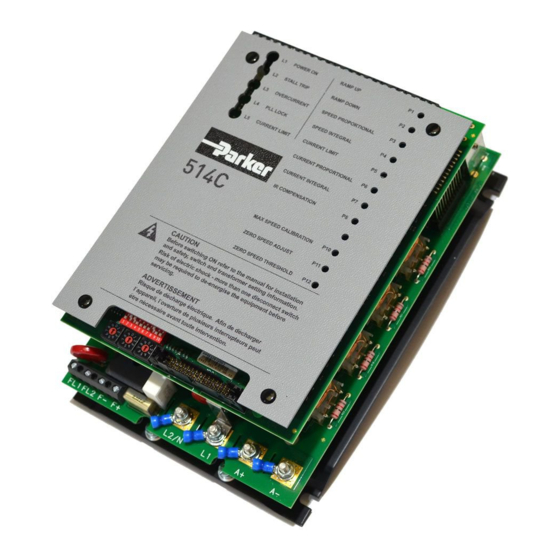
This manual was downloaded on www.sdsdrives.com +44 (0)117 938 1800 - info@sdsdrives.com Product Overview PRODUCT IDENTIFICATION AUXILIARY SUPPLY AUXILIARY SUPPLY SELECTOR SWITCH A1 A2 A3 A4 CONTROL TERMINAL BLOCK CONTROL 24 23 22 21 20 19 18 17 16 15 14 13 12 11 10 9 8 7 6 5 4 3 2 1 DIAGN OSTIC LEDS POTEN TIOMETERS L1 POWER ON... -
Page 9: Technical Specification
This manual was downloaded on www.sdsdrives.com +44 (0)117 938 1800 - info@sdsdrives.com Product Overview TECHNICAL SPECIFICATION General SPEED CONTROL Control Action Closed Loop with Proportional Integral Control and Adjustable Stability Speed Feedback Armature Voltage Tachogenerator 100% Load Regulation 2 % Typical 0.1 % Typical Maximum Torque/Speed Range 20:1... - Page 10 This manual was downloaded on www.sdsdrives.com +44 (0)117 938 1800 - info@sdsdrives.com Product Overview Electrical Ratings INPUT RATINGS SYMBOL 514C-04 514C-08 514C-16 514C-32 Supply Voltage 110 - 480 Vac 10% Maximum Supply 480Vac L - L Non earth referenced (IT)
-
Page 11: Environmental Requirements
This manual was downloaded on www.sdsdrives.com +44 (0)117 938 1800 - info@sdsdrives.com Product Overview Mechanical 514C-04 514C-08 514C-16 514C-32 Overall Width 160mm Overall Height 240mm Overall Depth 90mm 90mm 130mm 130mm Weight 1.6Kg 1.6Kg 3.0Kg 3.0Kg Airflow Clearance 75mm Above and Below... -
Page 12: Emc Technical Ratings
This manual was downloaded on www.sdsdrives.com +44 (0)117 938 1800 - info@sdsdrives.com Product Overview EMC TECHNICAL RATINGS Immunity Port Phenomenon Test Standard Level Criterion Generic Standard Enclosure BS EN 61000-4-2 8kV AD Self Recovery EN50082-1 Port RF Field (1995) 10V/m,1kHz, AM No Change (1992), RF Field Pulse... -
Page 13: Chapter 2 Pre-Installation Planning
This manual was downloaded on www.sdsdrives.com +44 (0)117 938 1800 - info@sdsdrives.com Pre-Installation Planning Chapter 2 Pre-Installation Planning BASIC WIRING DIAGRAMS Basic Connection Mains Supply Branch Protection (Fuses or Circuit Breaker) AC Supply Contactor Auxillary AC Supply Signal Ground 9 10 11 12 15 16 19 L2/N... -
Page 14: Terminal Descriptions
This manual was downloaded on www.sdsdrives.com +44 (0)117 938 1800 - info@sdsdrives.com Pre-Installation Planning TERMINAL DESCRIPTIONS Control Terminals TERMINAL FUNCTION DESCRIPTION NOTES Tacho Feedback Motor Mounted Tachogenerator Input. +350 Vdc Max. Approx 220 kohm. Proportional to Motor Speed. Not Connected Speed Meter Output Analogue Output, 5mA output 0 to 10V for 0 to 100% Speed. - Page 15 This manual was downloaded on www.sdsdrives.com +44 (0)117 938 1800 - info@sdsdrives.com Pre-Installation Planning TERMINAL FUNCTION DESCRIPTION NOTES Current Demand Analogue Input or Output: 5mA output Input / Output SW1/8 'ON' = Current Demand S/C protected approx. Output. 100 kohm. SW1/8 'OFF' = Current Demand Input.
-
Page 16: Terminal Comparison 540/1 To 514C
This manual was downloaded on www.sdsdrives.com +44 (0)117 938 1800 - info@sdsdrives.com Pre-Installation Planning TERMINAL COMPARISON 540/1 TO 514C Function Terminal Terminal 540/1 514C Common Armature Current (Direct) Setpoint Ramp Reset Setpoint Ramp Input Setpoint Ramp Output Setpoint Input 1 - Positive Trim Speed Setpoint I/P Setpoint Input 2 Inverted Sub-Total Output - Inverted Setpoint Sum O/P Setpoint Input 3 (Inverted) - Negative Trim Speed Setpoint I/P... - Page 17 This manual was downloaded on www.sdsdrives.com +44 (0)117 938 1800 - info@sdsdrives.com Pre-Installation Planning Function Terminal Terminal 540/1 514C Common T8/11 Thermistor Auxiliary Enable +24V Enable Maintain Start / Run Ready Output Zero Speed Output Drive Operational / Health +24V Unused DO NOT USE Pending Change Stall Override...
- Page 18 This manual was downloaded on www.sdsdrives.com +44 (0)117 938 1800 - info@sdsdrives.com Pre-Installation Planning Auxiliary Supply Terminals TERMINAL FUNCTION DESCRIPTION NOTES AC Supply AC Supply to AC Supply 540/1 Terminal D12 Contactor Coil. Contactor Switched Live. AC Supply AC Supply to AC Supply 540/1 Terminal D11 Contactor Coil.
-
Page 19: Block Diagram
0 V (SIGNAL ) SUPPL Y THERM ISTOR/ FL 2 ISOL ATION M ICROTHERM BOUNDARY DRAWN CHECKED TITLE USED ON ISSUE DATE ELECTRICAL SYMBOLS GENERALLY TO BS 3939 19.02.2007 BLOCK DIAGRAM FOR DRAWING NUM BER SHT. TRACED DESIGN APP. PARKER SSD DRIVES HH463070F101... -
Page 20: Functional Differences 514C - 540
This manual was downloaded on www.sdsdrives.com +44 (0)117 938 1800 - info@sdsdrives.com Pre-Installation Planning FUNCTIONAL DIFFERENCES 514C - 540 Feature 540 Series 514C Overload Inverse Time reduced Current Stall Detection & Timed Inhibit. Limit. Overload 200% for 10 seconds. 150% for 60 seconds. Overcurrent 300% Instantaneous Trip. -
Page 21: Chapter 3 Installation Procedure
1 2 3 4 5 6 7 8 9 10 DIAGNOSTIC SOCKET Tens Unit Tenths FL1 FL2 F- F+ L2 / N (measurement for 514C-04 and 08) (measurement for 514C-16 and 32) PRODUCT OVERALL DIMENSIONS FIXING SIZE SLOT DETAIL CENTRES... - Page 22 4 Holes M6 Clearance 230mm Leads M5 Ring Lugs LOAD Green Black /Yellow Product Filter Watt Overall Dimensions Fixing Product Terminal Loss Centres Fixing 514C-04 CO389113 18W 264 514C-08 CO389113 18W 264 514C-16 CO389113 18W 264 514C-32 CO389114 36W 264 514C Product Manual...
-
Page 23: Installation Information
5) Isolated control wiring should not be run close to the power cabling. If screened cables are used (recommended on setpoints and tachogenerators) connect screens to earth only at controller end. 6) Parker Hannifin Manufacturing Limited can supply fuse assemblies which can be bulkhead mounted and also act as convenient supply isolators. 514C Product Manual... - Page 24 This manual was downloaded on www.sdsdrives.com +44 (0)117 938 1800 - info@sdsdrives.com Setting up & Commissioning Function Rating Cable Size Fuse Isolator Kit Fuse Rating Parker Part 514C-04 Supply /16AWG LA057605U012 12A fuse CH390123 1.5mm Motor (10A U.S.) 1.5mm /16AWG Ground 1.5mm...
-
Page 25: Requirements For Ul Compliance
The field grounding terminal is a single screw, sized No. 10 (M5). UL Listed (ZMVV) pressure wire connectors rated No. 14 AWG (copper) must be used for Models 514C-04, 514C-08. UL Listed (SMVV) pressure wire connectors rated No. 10 AWG (copper) must be used for Models 514C-16. -
Page 26: Chapter 4 Setting-Up & Commissioning
This manual was downloaded on www.sdsdrives.com +44 (0)117 938 1800 - info@sdsdrives.com Setting up & Commissioning Chapter 4 Setting-Up & Commissioning OPTION SWITCHES Speed Feedback SW1/1 SW1/2 FEEDBACK VOLTAGE 10 - 25V USE P10 TO TRIM 25 - 75V MAXIMUM SPEED 75 - 125V TO REQUIRED 125 - 325V... -
Page 27: Potentiometers
This manual was downloaded on www.sdsdrives.com +44 (0)117 938 1800 - info@sdsdrives.com Setting up & Commissioning Current Calibration Current Calibration is achieved using the BCD switches SW2, 3 and 4 where SW2 represents the 'Tens'; SW3 represents the 'Units' and SW4 represents the 'Tenths'. Thus a 16.5 amp calibration is achieved by setting switch SW2 to 1, SW3 to 6, and SW4 to 5. -
Page 28: Basic Setting-Up Procedure
This manual was downloaded on www.sdsdrives.com +44 (0)117 938 1800 - info@sdsdrives.com Setting up & Commissioning BASIC SETTING-UP PROCEDURE Preliminary Precautions BEFORE ATTEMPTING TO CONNECT POWER:- CONTROLLER Check:- The Auxiliary Supply Voltage is correctly selected on the Power Board. The Main Power Supply Voltage is within the operating range of the controller. The Armature Voltage and current ratings are compatible with controller supplied. - Page 29 This manual was downloaded on www.sdsdrives.com +44 (0)117 938 1800 - info@sdsdrives.com Setting up & Commissioning Check switch selection SW1/1 ) Speed Range (see table 4.1) SW1/2 ) SW1/3 Tachogenerator / VA (see switch options on page 4.1) SW1/4 Zero Speed / Zero Setpoint (see switch options on page 4.1) SW1/5 Current Meter Output SW1/6...
- Page 30 This manual was downloaded on www.sdsdrives.com +44 (0)117 938 1800 - info@sdsdrives.com Setting up & Commissioning Check that a speed demand signal is available. This will normally appear as an input to the Setpoint Ramp on terminal T13 (diagnostic test point 11). Additional setpoint inputs may also appear at: Positive trim, terminal T10 (diagnostic 12) Negative trim, terminal T17 (diagnostic 13)
- Page 31 This manual was downloaded on www.sdsdrives.com +44 (0)117 938 1800 - info@sdsdrives.com Setting up & Commissioning Before altering any connections make sure that all Auxiliary and Main power supplies are totally isolated from the drive and equipment and that the motor is stationary. Adjust the Speed Setpoint so that the Total Setpoint voltage is about 0.5 Volts (terminal T12, Diagnostic 15).
-
Page 32: Running Performance Adjustments
If the controller is operating in tachogenerator mode the IR compensation potentiometer (P8) must be anti-clockwise. The Proportional and Integral potentiometers (P3, P4, P6, P7) as preset by Parker Hannifin Manufacturing Limited will provide stable and responsive performance under most load conditions. - Page 33 This manual was downloaded on www.sdsdrives.com +44 (0)117 938 1800 - info@sdsdrives.com Setting up & Commissioning and then remain steady. If necessary adjust P6 and P7 slowly to obtain a Critically Damped performance, i.e., the fastest response possible without overshoot, as shown in Figure 3. Figures 1 and 2 show typical armature current waveforms where P6 and P7 are incorrectly set and indicate the adjustment required to improve the drive performance to conform to that of Figure 3.
-
Page 34: Chapter 5 Diagnostics And Fault Finding
This manual was downloaded on www.sdsdrives.com +44 (0)117 938 1800 - info@sdsdrives.com Diagnostics and Fault Finding Chapter 5 Diagnostics and Fault Finding DIAGNOSTIC LEDS LED1 POWER ON Illuminated when the Auxiliary Supply is energised. LED2 STALL TRIP Illuminated when the Controller has detected a Stall or Current Limit Condition for more than 60 seconds. -
Page 35: Drive Trips
This manual was downloaded on www.sdsdrives.com +44 (0)117 938 1800 - info@sdsdrives.com Diagnostics and Fault Finding DRIVE TRIPS When a fault occurs the drive will trip and display the cause of the trip on the indicator LEDs or on the diagnostic (test point 6) for the Thermistor/Microtherm Trip. The Stall Trip (LED2 on) and the Thermistor/Microtherm Trip are reset by re-applying the run signal to Terminal 5. - Page 36 This manual was downloaded on www.sdsdrives.com +44 (0)117 938 1800 - info@sdsdrives.com Diagnostics and Fault Finding Test Condition Voltage Description Node Total Setpoint Sum 100% Forward Speed +10V Terminal T12 Zero Speed 100% Reverse Speed -10V Speed Feedback 100% Forward Speed -2.7V Zero Speed 100% Reverse Speed...
-
Page 37: Troubleshooting
This manual was downloaded on www.sdsdrives.com +44 (0)117 938 1800 - info@sdsdrives.com Diagnostics and Fault Finding TROUBLESHOOTING PROBLEM POSSIBLE CAUSE REMEDY "Power On" LED 1 No Auxiliary Supply Check Auxiliary Supply Availability. Is the Not Illuminated Available. Supply Fuse fitted or the Circuit Breaker closed? Auxiliary Supply Fuse. - Page 38 This manual was downloaded on www.sdsdrives.com +44 (0)117 938 1800 - info@sdsdrives.com Diagnostics and Fault Finding PROBLEM POSSIBLE CAUSE REMEDY Motor Runs but stops Overcurrent. Check Motor wiring and Motor for after a period with earth faults. "Overcurrent Trip" Check controller for Faulty Thyristor LED 3 Illuminated.
-
Page 39: Chapter 6 Certification
Voltage Directive and, in some instances, the EMC Directive. CE Marking for Low Voltage Directive When installed in accordance with this manual, the 514C Converter is CE marked by Parker Hannifin Manufacturing Limited in accordance with the low voltage directive (S.I. No. 3260 implements this LVD directive into UK law). - Page 40 It is important that you have now defined who is responsible for conforming to the EMC directive, either: Parker Hannifin Manufacturing Limited Responsibility You intend to use the unit as relevant apparatus. When the specified EMC filter is correctly fitted to the unit following EMC installation instructions, it complies with the relevant standards indicated in the following tables.
- Page 41 Dr Martin Payn ( EME Division Engineering Manager) * Compliant with the immunity requirements of the Standard without specified EMC filters. Parker Hannifin Manufacturing Limited, Automation Group, Electromechanical Drives Business Unit, NEW COURTWICK LANE, LITTLEHAMPTON, WEST SUSSEX BN17 7RZ TELEPHONE: +44(0)1903 737000 FAX: +44(0)1903 737100 Registered Number: 4806503 England.
-
Page 42: Chapter 7 Service And Repair
Service and Repair Chapter 7 Service and Repair The product has no user serviceable parts and should be returned to Parker Hannifin Manufacturing Limited for repair. The product should be returned in the original packaging if possible or else reasonable care should be taken in the packing of the product to ensure that no transport damage be incurred. - Page 43 (from AT, BE, CH, CZ, DE, EE, ES, FI, FR, IE, IL, IS, IT, LU, MT, NL, NO, PT, SE, SK, UK) © 2016 Parker Hannifin Corporation. All rights reserved. Parker Hannifin Manufacturing Limited, Automation Group, Electromechanical Drives Business Unit,...
Need help?
Do you have a question about the 514C-04 and is the answer not in the manual?
Questions and answers