
Subscribe to Our Youtube Channel
Related Manuals for Parker 507


Summary of Contents for Parker 507
- Page 1 506 / 507 / 508 climate control electromechanical filtration DC Controller fluid & gas handling hydraulics HA389427 Issue 14 pneumatics Technical Manual process control sealing & shielding...
- Page 2 All rights strictly reserved. No part of this document may be stored in a retrieval system, or transmitted in any form or by any means to persons not employed by a Parker Hannifin Manufacturing Limited without written permission from Parker Hannifin Manufacturing Ltd . Although every effort has been taken to ensure the accuracy of this document it may be necessary, without notice, to make amendments or correct omissions.
- Page 3 Parker or its subsidiaries or authorized distributors. To the extent that Parker or its subsidiaries or authorized...
- Page 4 Safety Information Requirements Please read this information BEFORE installing the equipment. IMPORTANT: Intended Users This manual is to be made available to all persons who are required to install, configure or service equipment described herein, or any other associated operation. The information given is intended to highlight safety issues, EMC considerations, and to enable the user to obtain maximum benefit from the equipment.
- Page 5 Safety Information Hazards DANGER! - Ignoring the following may result in injury 1. This equipment can endanger life by 5. For measurements use only a meter exposure to rotating machinery and to IEC 61010 (CAT III or higher). high voltages. Always begin using the highest range.
- Page 6 When replacing a drive in an All exposed metalwork in the Inverter application and before returning to use, is protected by basic insulation and it is essential that all user defined bonded to a safety earth. parameters for the product’s operation ...
-
Page 7: Table Of Contents
Contents Contents Page HAPTER RODUCT VERVIEW Description ............................. 1-1 Product Range ..........................1-1 506/507/508 HAPTER VERVIEW OF THE HAPTER ERMINAL ESCRIPTION Control Terminals ...................... 3-1 Power Terminals ......................3-2 Auxiliary Terminals ....................3-2 Switches ........................3-3 Potentiometers ......................3-3 LEDS ......................... 3-3... - Page 8 Applying Power .......................... 4-10 Fault Finding ..........................4-12 HAPTER OUTINE AINTENANCE AND EPAIR Routine Maintenance ........................5-1 Repair ............................... 5-1 Returning the Unit to Parker Hannifin Manufacturing Limited ........5-1 6 EMC C 506/507/508 HAPTER ERTIFICATION FOR Certificates ........................ 6-1 HAPTER ECHNICAL PECIFICATIONS Input Supply ......................
-
Page 9: Chapter 1 Product Overview
VERVIEW Chapter 1 Description The 506/507/508 series controllers are compact, non-isolated motor speed controllers specifically designed for dc shunt would and permanent magnet motors. The controllers are intended to operate from a single phase AC mains supply in the ranges 110/120V AC or 220/240V AC 50/60Hz. -
Page 10: Chapter 2 Overview Of The 506/507/508
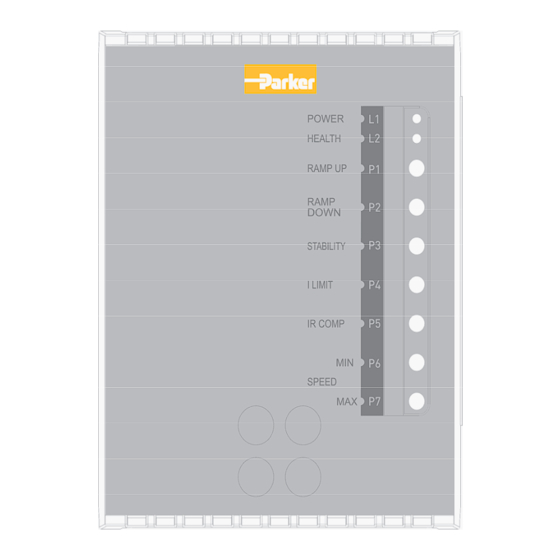
Overview of the 506/507/508 506/507/508 VERVIEW OF THE Chapter 2 Figure 2.1 Recognition Drawing Auxiliary Inputs Control Note: Auxiliary Customer Terminal is 1 2 3 4 Personal Switches not fitted on standard Indicators models but a special build can be... -
Page 11: Chapter 3 Terminal Description
This is a non-isolated product. The control connections are not isolated from the AC supply. Any connection to earth or use of earth (ground) referenced components either deliberately or unintentionally will cause permanent damage to the controller. 506/507/508 - HA389427... -
Page 12: Power Terminals
Collector * Health Health Output 24V at 50mA open Collector * Zero Speed Level Zero Speed Output For other levels see Table 3.1 Level Trim Auxiliary Setpoint Auxiliary Direct Speed +10V @ 100K Full Setpoint Speed Input 506/507/508 - HA389427... -
Page 13: Switches
Switches Switch Imax. 506 - 0.25 to 1.5A Imax. 506 - 0.5 to 3.0A Imax. 507 - 0.5 to 3.0A Imax. 507 - 1.0 to 6.0A Imax. 508 - 1.0 to 6.0A Imax. 508 - 2.0 to 12.0A ½ Speed Demand Full Speed Demand ¼... -
Page 14: Chapter 4 Installing The
Installing the 506/507/508 506/507/508 NSTALLING THE Chapter 4 Installation Speed Control Figure 4.1 Wiring Diagram Speed Control Fuse Fuse MAINS L2/N FILTER I LIMIT + 10 V SETPOINT COMMON neutral Double/reinforced insolation boundary provided by users TACHO GENERATOR potentiometer and run switch Additional line fuse recommended for applications where live connections are made rather than live and neutral. -
Page 15: Wire Sizes
Installing the 506/507/508 WARNING! Ensure that all wiring is electrically isolated and cannot be made "live" unintentionally by other personnel. Wire Sizes * Contains semiconductor fuses as recommended below. Model Maximum Function Cable AC Supply Parker Fuse Isolator Output (Wire) Size... -
Page 16: Requirements For Ul Compliance
Short Circuit Rating The 506 and 507 controllers are suitable for use on a circuit capable of delivering not more than 1000 RMS symmetrical amperes, 240V maximum; whilst the 508 controller is suitable for use on a circuit capable of delivering not more than 5000 rms symmetrical amperes, 240V maximum. -
Page 17: Block Diagram
Installing the 506/507/508 Installing the 506/507/508 Block Diagram TRANSFORMER SELECTION SWITCH +12V 220/240 LED 1 110/120 POWER POWER QUENCH SUPPLY -10V REF +10V REF -12V 0V COMMON LED 2 HEALTH +16V STALL DRIVE HEALTH HEALTHY PROTECTION TORQUE / TORQUE/CURRENT LIMIT 10V = 100%... -
Page 18: Terminal Tightening Torque
Installing the 506/507/508 Terminal Tightening Torque Refer to the Terminal Tightening torque table shown on page 4-2 for both the Power and Control Terminals. Field Grounding Terminals The field grounding terminals are identified with the International Grounding Symbol (IEC Publication 417, Symbol 5019). -
Page 19: Removing The Cover
Installing the 506/507/508 IP20 80 mm 80 mm 90 mm 84 mm 84 mm 84 mm 140 mm 140 mm 140 mm 105 mm 105 mm 105 mm 50 mm 50 mm 50 mm 140 mm 140 mm 140 mm... -
Page 20: Filter
Installing the 506/507/508 Filter Figure 4.4 Filter Mechanical Arrangement LINE L2 L1 PE END USER TO AFFIX OWN DIN RAIL HERE TO MOUNT DRIVE 4 x M5 Inserts for DIN Rail Mounting at chosen height 200mm 4 Holes M6 Clearance... -
Page 21: Emc Connections
Installing the 506/507/508 EMC Connections Figure 4.5 Wiring Diagram Mains Filter Screened Cable DC Motor Product AC Supply Filter Grd (PE) Grd (PE) Grd (PE) Installation and Set-Up Warning Before applying power check:- Switch Selection (a) Mains switch set to intended supply voltage, Left 110/120, Right 220/240 (b) Personality switches. -
Page 22: Potentiometer
4-10 Installing the 506/507/508 Note: Even when intending to utilise tachogenerator feedback it may be wise to initially run under armature control. Set feedback voltage switches accordingly. Note that if this procedure is followed the tachogenerator must be temporarily disconnected as it will affect operation of the controller. - Page 23 4-11 Installing the 506/507/508 If the controller is in “Tacho” control then excess speed is due to incorrect polarity of feedback. Alter wiring as follows:- Problem Action Direction correct but Reverse Tachogenerator polarity only. overspeeding. Direction incorrect and overspeeding. Reverse field polarity only.
-
Page 24: Fault Finding
4-12 Installing the 506/507/508 Fault Finding Problem Possible Cause Remedy Controller will not Wrong supply voltage. Check setting on mains switch. power up - no ‘on’ It is likely that if too high a indication. voltage has been used the... - Page 25 4-13 Installing the 506/507/508 Problem Possible Cause Remedy Motor will not run at Wrong speed range Refer to Installation and Set-up correct maximum selection on preset chapter. speed. switches. Stall light comes on Incorrect wiring of run Run contact should be wired after 15 seconds in contact.
-
Page 26: Routine Maintenance
IMPORTANT: MAKE NO ATTEMPT TO REPAIR THE UNIT - RETURN IT TO PARKER HANNIFIN MANUFACTURING LIMITED. Returning the Unit to Parker Hannifin Manufacturing Limited Please have the following information available: The model and serial number - see the unit’s rating label ... -
Page 27: Emc Certification For Certificates
Dr Martin Payn EME Division Engineering Manager * Compliant with the immunity requirements of the Standard without specified EMC filters. Parker Hannifin Manufacturing Limited, Automation Group, Electromechanical Drives Business Unit, NEW COURTWICK LANE, LITTLEHAMPTON, WEST SUSSEX BN17 7RZ TELEPHONE: +44(0)1903 737000 FAX: +44(0)1903 737100 Registered Number: 4806503 England. -
Page 28: Chapter 7 Technical Specifications
All control terminals are at a potential of the peak of the input supply with respect to earth (ground) All cables should be rated for this voltage. Parameter Symbol Value Units Overspeed limiting Standard Type of controller Fixed proportional plus integral Feedback method Non-isolated shunt Linearity 506/507/508 - HA389427... -
Page 29: Adjustment Range
2000m Atmosphere Non-flammable, non-corrosive and dust free Storage Temperature Range C to +55 Transport Temperature Range -25 C to +55 Enclosure IP2X suitable for cubicle mounting Installation Category Overvoltage Category III. Pollution Pollution Degree 2. 506/507/508 - HA389427... -
Page 30: Emc Technical Ratings
Supply Filter. * Achieved with up to 50m of motor cable. Port Phenomenon Test Standard Level Generic Standard Enclosure Port Radiated EN55011 Class B EN50081-1 (1992) Power Port Conducted EN55011 Class B* EN50081-2 (1994) 506/507/508 - HA389427... -
Page 31: Electrical Ratings
Field Voltage (0.9 x Vs) V dc 110/120V AC 90-100 220/240V AC 180-200 Adjustment Ranges Range selected by built in switches. Parameter Maximum current * (l max, A) 0.25 - 3 0.5 - 6 1 - 12 506/507/508 - HA389427... -
Page 32: Product Code
Technical Specifications Product Code Block Product Code Feature Basic Product 3 Amp 6 Amp 12 Amp Livery Standard 01 to 99 Customer Cover IP20 Cover Special Options Standard 01 to 99 Documented Special Options 506/507/508 - HA389427... - Page 33 Free phone: 00 800 27 27 5374 (from AT, BE, CH, CZ, DE, EE, ES, FI, FR, IE, IL, IS, IT, LU, MT, NL, NO, PT, SE, SK, UK) © 2016 Parker Hannifin Corporation. All rights reserved. Parker Hannifin Manufacturing Limited, Automation Group,...
Need help?
Do you have a question about the 507 and is the answer not in the manual?
Questions and answers