Table of Contents
Advertisement
Quick Links
Advertisement
Table of Contents

Subscribe to Our Youtube Channel
Related Manuals for Parker 512C


Summary of Contents for Parker 512C
- Page 1 This manual was downloaded on www.sdsdrives.com +44 (0)117 938 1800 - info@sdsdrives.com aerospace 512C climate control electromechanical filtration DC Controller fluid & gas handling hydraulics HA389196 Issue 11 pneumatics Technical Manual process control sealing & shielding...
- Page 2 Parker or its subsidiaries or authorized distributors. To the extent that Parker or its subsidiaries or authorized...
- Page 3 All rights strictly reserved. No part of this document may be stored in a retrieval system, or transmitted in any form or by any means to persons not employed by a Parker Hannifin Manufacturing Limited company without written permission from Parker Hannifin Manufacturing Ltd. Although every effort has been taken to ensure the accuracy of this document it may be necessary, without notice, to make amendments or correct omissions.
- Page 4 This manual was downloaded on www.sdsdrives.com +44 (0)117 938 1800 - info@sdsdrives.com IMPORTANT: Please read this information BEFORE installing the equipment. Intended Users This manual is to be made available to all persons who are required to install, configure or service equipment described herein, or any other associated operation.
- Page 5 This manual was downloaded on www.sdsdrives.com +44 (0)117 938 1800 - info@sdsdrives.com DANGER! - Ignoring the following may result in injury 1. This equipment can endanger life by exposure to 5. For measurements use only a meter to IEC 61010 (CAT rotating machinery and high voltages.
-
Page 6: Table Of Contents
This manual was downloaded on www.sdsdrives.com +44 (0)117 938 1800 - info@sdsdrives.com Contents Contents Page HAPTER ETTING TARTED Introduction ........................... 1-1 Optional Equipment ....................1-1 Equipment Inspection ......................... 1-1 About this Manual ........................1-2 Initial Steps ......................1-2 How the Manual is Organised ................. 1-2 HAPTER VERVIEW OF THE ONVERTER... - Page 7 This manual was downloaded on www.sdsdrives.com +44 (0)117 938 1800 - info@sdsdrives.com Contents Contents Page Routine Maintenance ........................8-1 Repair ............................... 8-1 Returning the Unit to Parker Hannifin Manufacturing Limited ........8-1 Disposal ......................... 8-1 512C HAPTER EPLACEMENT OF WITH 512C/512 Terminal Differences ....................9-1 Functional Differences 512C &...
-
Page 8: Getting Started
Chapter 1 Introduction The 512C converter is intended for use in an Industrial Environment, it should be mounted within an enclosure which provides protection to the converter and the user. The converter should be permanently earthed at the terminals provided. -
Page 9: About This Manual
Getting Started About this Manual This manual is intended for use by the installer of the 512C converter. It assumes a reasonable level of understanding in these disciplines. Note: Please read all Safety Information before proceeding with the installation and operation of this unit. -
Page 10: An Overview Of The Converter
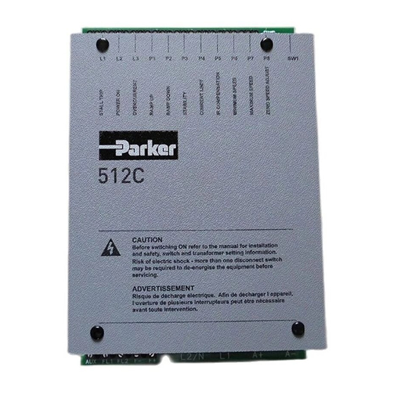
P8 - ZERO SPEED OFFSET 380/415V LEGEND 220/240V 110/120V TRANSFORMER PLATE TAPPING LINK MAINS MAINS OR AUXILIARY SUPPLY SELECTOR HEATSINK FIXING POINTS POWER TERMINALS FIELD TERMINALS & AUXILIARY SUPPLY PROTECTIVE GROUND Figure 2-1 View of Component Parts 512C Series Converter... -
Page 11: Control Features
0 to +10V Total Setpoint 0 to +10V +10V Reference +10V -10V Reference - 10V Digital Inputs +10 to 100Kohm +24V Stall Override 100Kohm Digital Outputs Health +24V 50mA Source Zero Speed or +24V 50mA Setpoint Source 512C Series Converter... -
Page 12: Understanding The Product Code
Two numbers specifying mechanical package including livery and mechanical package style, and any option installed over and above the standard features of the product: Two numbers Livery Standard Parker Hannifin Manufacturing Limited livery 01-99 Defined customer liveries Two numbers specifying the cover: IP00 Open Frame... -
Page 13: Chapter 3 Installing The Converter
FIXING CENTRES SIZE SLOT DETAIL 512C-04 240mm 160mm 90mm 210mm 148mm 15mm 512C-08 240mm 160mm 90mm 210mm 148mm 15mm 512C-16 240mm 160mm 90mm 210mm 148mm 15mm 512C-32 240mm 160mm 130mm 210mm 148mm 15mm Table 3.1 Product Dimensions 512C Series Converter... -
Page 14: Mounting The Converter
Fixing Centres Product Fixing Terminal Loss 512C-04 CO389113 165 45 240 4mm 2 512C-08 CO389113 165 45 240 4mm 2 512C-16 CO389113 165 45 240 4mm 2 512C-32 CO389114 165 70 240 6mm 2 Table 3.2 Filter Installation Information 512C Series Converter... - Page 15 Terminal Tightening Torque 0.6 Nm, 4.5 lbf-in M5 Studs with Clamp. Power Terminals Terminal Tightening Torque 2.7 Nm, 24 lbf-in M5 Cheese Head Screw. Earth Terminals Terminal Tightening Torque 7.1 Nm, 63 lbf-in Table 3.3 Motor Information 512C Series Converter...
-
Page 16: Electrical Installation
This can be achieved by either connecting two earthing conductors of the required value, see table 11.1, or connecting one earthing conductor of at least 10mm IMPORTANT: The Converter fitted with an internal or external ac supply EMC filter is only suitable for earth referenced supplies (TN). 512C Series Converter... -
Page 17: Chapter 4 Operating The Converter
In a system comprising of more than one controller, the “0V/common” signals should be connected together and joined to protective earth/ground at one point only. Stall override link between terminals 14 and 15 required when using controller in current control. 512C Series Converter... -
Page 18: Setting-Up & Commissioning
Using 512/16 - From table 4.2 set SW7 ON, SW6 ON, SW5 OFF Ia = 14 Amp Option 2 Using 512/32 From table 4.2 set SW7 OFF, SW6 ON, SW5 ON - Ical = 16 Amp Turn down I Limit (P4) to give 14 Amps 512C Series Converter... -
Page 19: Potentiometers
Current Motor Scaling SW8 (OFF) Current Meter Buffered Current Meter Output 5V Equivalent to 100% of Controller Current Rating. i.e. 4 Amp on 512C/04 8 Amp on 512C/08 16 Amp on 512C/16 32 Amp on 512C/32 (ON) Current Meter Buffered Current Meter Output 5V Equivalent to 100% of Calibrated Current Rating. -
Page 20: Basic Setting-Up Procedure
(i.e. fire bar elements) in series with the motor armature. If it is possible to rotate the motor, and tachogenerator feedback is in use, check that forward rotation results in positive tacho feedback, i.e. terminal 1 is positive with respect to terminal 8 or 11. 512C Series Converter... - Page 21 Set the Ramp Up time (P1) and Ramp Down time (P2) to the required rates. With armature voltage feedback, speed droop will occur as load is applied to the motor. Set the IR Compensation (P5) to remove this effect, note excessive adjustment may cause instability. 512C Series Converter...
- Page 22 Monitor the armature current as indicated on terminal 6 the current meter output, verify that that at steady state the current does not exceed the controller rating, i.e. the voltage on T6 is not greater than 5V with SW8 OFF. 512C Series Converter...
-
Page 23: Chapter 5 Led Indications
Illuminated when power supplied to Auxiliary Supply either directly or via the Auxiliary terminal. LED3 OVERCURRENT Illuminated when Armature Current exceeds 3½ times Calibrated Current. S T A LL OV E R CU R R E N T P OW E R ON 512C Series Converter... -
Page 24: Terminal Descriptions
Not Connected Health Output Digital Output, 50mA Source +24V = Healthy Unprotected Not Connected Not Connected Not Connected Zero Speed Output / Digital Output, 50mA Source Zero Setpoint Output +24V = Running Unprotected 0V = Stopped Not Connected 512C Series Converter... -
Page 25: Power Terminals
* Aux L1 Auxiliary Supply Auxiliary Supply Input to Control Auxiliary Supply Return via Transformer. L2/N The signal applied to Aux L1 must be in phase with L1 in order to provide the correct coding for the controller. 512C Series Converter... -
Page 26: Chapter 7 Fault Finding
Motor runs with Zero Zero Speed Offset Adjustment Adjust P8 to give Zero Speed Setpoint. Motor Speed Stability P3 Reduce P3 Oscillating IR Compensation P5 No IR compensation for Tachogenerator Feedback. Reduce P5 for Armature Voltage Feedback 512C Series Converter... -
Page 27: Routine Maintenance & Repair
Remove this using dry air. Repair There are no user-serviceable components. IMPORTANT: MAKE NO ATTEMPT TO REPAIR THE UNIT - RETURN IT TO PARKER HANNIFIN MANUFACTURING LIMITED. Returning the Unit to Parker Hannifin Manufacturing Ltd Please have the following information available: ... -
Page 28: Chapter 9 Replacement Of 512 With 512C
This manual was downloaded on www.sdsdrives.com +44 (0)117 938 1800 - info@sdsdrives.com Replacement of 512 with 512C 512C EPLACEMENT OF WITH Chapter 9 512C/512 Terminal Differences TERMINAL 512C COMMENTS Tacho Feedback Tacho Feedback Not Connected Not Connected Speed Meter Output... -
Page 29: Functional Differences 512C & 512
WARNING THE 512C IS NOT A DIRECT REPLACEMENT FOR THE 512 IT IS FUNCTIONALLY EQUIVALENT. WHEN A 512C IS USED TO REPLACE A 512 WITH THE HEALTH AND/OR ZERO SPEED RELAYS UTILISED, EXTERNAL RELAYS MUST BE PROVIDED. CARE MUST ALSO BE TAKEN TO AVOID CONNECTING LIVE PARTS TO THE RELAY OUTPUT DRIVER TERMINALS. -
Page 30: Chapter 10 Block Diagram
This manual was downloaded on www.sdsdrives.com +44 (0)117 938 1800 - info@sdsdrives.com 10-1 Block Diagram LOCK IAGRAM Chapter 10 Block Diagram 512C Series Converter... -
Page 31: Chapter 11 Technical Specifications
Power cable to be minimum 600V AC rated at 1.5 x armature current. High speed semi-conductor fuses of the correct rating are recommended controller semi- conductor protection, as the 512C is not internally fused. The suitability of the semi- conductor fuse branch protection should be decided by the installer. - Page 32 Smaller cable may be used if the controller is calibrated at a lower current level. Terminal Tightening Torques Control & Field 0.6 Nm 0.4 lbf-ft 4.5 lbf-in Power 2.7 Nm 2 lbf-ft 24 lbf-in Earth 7.1 Nm 5.25 lbf-ft 63 lbf-in 512C Series Converter...
-
Page 33: Electrical Ratings
Without Filter Current at 480Vac With Filter 50mA Note: 460/480 Vac Operation is available when used with an auxiliary supply input of a suitable standard value. See page 3-2 for filter watt loss information. Permanent earthing mandatory. 512C Series Converter... -
Page 34: Certification For The Converter
(at least) the motor, cable and a driven load before providing intrinsic function to the end user. As such the majority of Parker Hannifin Manufacturing Limited products are categorised as components (CEMEP validity field 2) and it would be incorrect for Parker Hannifin Manufacturing Limited to apply the CE mark or produce an EC Declaration of Conformity in respect of EMC. -
Page 35: Special Considerations For Installations Requiring Compliance With Ul Standards
These controllers are suitable for use on a circuit capable of delivering not more than 5000 RMS symmetrical amperes, 480 V Maximum. Field Wiring Temperature Rating Use 60C or 60/75C Copper Conductors only. Grounding The field grounding terminal is identified by the International Grounding Symbol (IEC Publication 417, Symbol 5019). 512C Series Converter... -
Page 36: Certificates
01 June 2016 Dr Martin Payn. EME Drives Division Engineering Manager * Compliant with the immunity requirements of the Standard without specified EMC filters. Parker Hannifin Manufacturing Limited, Automation Group, Electromechanical Drives Business Unite NEW COURTWICK LANE, LITTLEHAMPTON, WEST SUSSEX BN17 7RZ... - Page 37 (from AT, BE, CH, CZ, DE, EE, ES, FI, FR, IE, IL, IS, IT, LU, MT, NL, NO, PT, SE, SK, UK) © 2016 Parker Hannifin Corporation. All rights reserved. Parker Hannifin Manufacturing Limited, Automation Group, Electromechanical Drives Business Unit,...
Need help?
Do you have a question about the 512C and is the answer not in the manual?
Questions and answers