Table of Contents
Advertisement
Quick Links
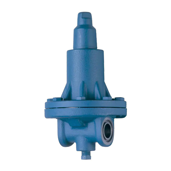
COMPACT
PRESSURE REGULATORS
Type A2B, A2A, A2BK, A2BOE
FOR AMMONIA, R12, R22, R502
AND OTHER COMMON REFRIGERANTS
FEATURES
• Compact Direct Diaphragm Operated
• Design Pressure (MRP): 27.6 bar (400 PSIG)
• Flanged Connections: FPT, SW, WN or ODS
• Available with Close Coupled Strainer
• Stainless Steel Diaphragm
Description
The A2 Type pressure regulators are compact, direct diaphragm operated,
for use with refrigerant liquid or vapor. The regulators can be used with
ammonia, R12, R-22, R-502, certain other refrigerants, oil and other
approved fluids with similar pressure temperature and corrosion
characteristics. The design pressure (MRP) is 21 bar (300 psig). The
regulators are for use in systems where a small inlet or outlet pressure
regulator is needed.
The regulators are furnished with flanges for FPT: Internal NPT (USA
Standard Taper Pipe Thread), socket weld, weld neck or ODS (solders
over copper tubing of given external diameter) connections. The
regulator can be easily removed for service.
A strainer can be furnished to close couple to the inlet of the regulator.
Refrigerating Specialties Division
050012
BULLETIN 21-02D
Type A2B, A2A, A2BK, A2BOE
January 2003
Installation, Service and Parts Information
Purpose
The A2B, A2BK and A2A are Inlet Pressure Regulators that prevent inlet
(or upstream) pressure from falling below set-point. They will tend to open
on a rise in inlet pressure above set-point and will be closed below set-point.
The A2BO and A2BOE are Outlet Pressure Regulators. (The A2BOE
senses outlet pressure through an external connection.) They prevent their
outlet (or downstream) pressure from rising above set-point. They tend to
open on a drop in outlet pressure below set-point and will be closed above
set-point.
Principles of Operation A2B, A2A
The inlet pressure acts on the diaphragm; when the force created by the
pressure exceeds the force of the range spring, the diaphragm is lifted off
of the valve seat and flow occurs between the diaphragm and the valve
seat, from the regulator inlet to the outlet. Increased inlet pressure lifts
the diaphragm further, allowing increased flow. Decrease in inlet pressure
causes the diaphragm to move closer to the valve seat, thus reducing the
flow. Thus, the regulator acts to maintain the inlet pressure approximately
constant. If the inlet pressure drops below the regulator setting, the
diaphragm closes off the flow to keep the inlet pressure from going below
the set point, subject to limits of seat leakage tolerance, or leakage due to
dirt particles on the seat surfaces.
Adjustment A2B, A2A
An accurate pressure gauge should be installed at the gauge connection
on the regulator or in the piping near the regulator inlet.
Carefully remove the seal cap by barely cracking it open to allow any
confined refrigerant to escape gradually. Then turn the adjusting stem in
(clockwise) to raise the set point, or out (counterclockwise) to lower the
set point. Table 1 shows the set point pressure ranges for the regulators.
Do not attempt to exceed the rated maximum pressure setting adjustment
because this could damage the regulator or make it inoperative. Severe
overadjusting could also apply enough force to damage the diaphragm
and valve seat or put the spring in solid position. So, if the maximum
tightening adjustment has been reached, stop and back out the adjusting
stem (counterclockwise) at least one half turn so the range spring can
move.
After adjusting the regulator it is advisable to observe the maintained
pressure while the system is operating normally and to make any minor
adjustments required at that time. Replace the seal cap after the desired
set point is reached.
TABLE 1. INLET PRESSURE SETTING RANGES
SET POINT RANGES
A: 0 to 10.3 bar (0 to 150 psig)
V: 500 mm Hg to 8 bar
(20 in. Hg to 120 psig)
D: 5 to 19 bar (75 to 280 psig)
1
I S O
9 0 0 1 - 2 0 0 0 C E R T I F I E D
APPROX. CHANGE PER TURN
OF ADJUSTING SCREW
1.7 bar (25 psi)
1.7 bar (25 psi)
3.6 bar (53 psi)
Advertisement
Table of Contents

Subscribe to Our Youtube Channel
Related Manuals for Parker A2B


Summary of Contents for Parker A2B
- Page 1 Installation, Service and Parts Information Purpose The A2B, A2BK and A2A are Inlet Pressure Regulators that prevent inlet (or upstream) pressure from falling below set-point. They will tend to open on a rise in inlet pressure above set-point and will be closed below set-point.
- Page 2 Follower, Diaphragm Bonnet/Spring Kit Ranges A & V 202008 Spring/Stem Kit (202006) Seal Cap Gasket Bonnet Screw, Hex Hd. Gasket A2B, A2BO Bonnet/Spring Kit Range D 202009 Spring/Stem Kit (202007) Seal Cap Gasket Bonnet Screw, Hex Hd. Gasket Bonnet/Spring Kit...
- Page 3 Make sure two diaphragms are used See appropriate adjustment for A2B and A2BO Range D and A2A Ranges A and D. Tighten the Bonnet procedure. Screws 11 gradually and evenly. The screws should be tightened by turning Wrong pressure range ..........
- Page 4 Flanges with ODS connections are not suitable for ammonia service. D: 5 to 19 bar (75 to 280 psig) 3.6 bar (53 psi) Parker Hannifin Corporation • Refrigerating Specialties Division Refrigerating Specialties Division 2445 South 25th Avenue • Broadview, IL 60155-3891...
Need help?
Do you have a question about the A2B and is the answer not in the manual?
Questions and answers