Table of Contents
Advertisement
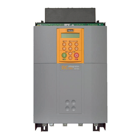
598/599P
External Stack
HA500841 Issue 3
Application Manual
This manual was downloaded on www.sdsdrives.com
+44 (0)117 938 1800 - info@sdsdrives.com
ENGINEERING
YOUR
aerospace
aerospace
climate control
climate control
electromechanical
fi ltration
fi ltration
fl uid & gas handling
fl uid & gas handling
hydraulics
hydraulics
pneumatics
pneumatics
process control
process control
sealing & shielding
sealing & shielding
SUCCESS.
Advertisement
Table of Contents

Related Manuals for Parker 599P


Summarization of Contents
Safety Information
Requirements
Important information and requirements before installing the equipment.
Intended Users
Defines the target audience for this application manual.
Application Area
Specifies the industrial application for the described equipment.
Personnel
Details the qualification requirements for personnel handling the equipment.
Product Warnings
Highlights critical warnings for electrical shock and documentation.
Hazards
Details the potential dangers and risks associated with the equipment's operation.
Safety
Covers general safety precautions, including EMC and wiring best practices.
Application Risk
Discusses risks related to fault conditions and unintended operation.
Risk Assessment
Examines fault condition impacts on motor control and system operation.
Overview
Outline Drawing
Visual representation of the external stack controller with dimensions and connections.
Electrical Installation
3-Phase Contactor
Guidance on connecting an AC line contactor for the power stack.
Auxiliary Supply
Details requirements for the single-phase AC auxiliary supply.
Semiconductor Fuses
Information on fuse selection for thyristors and field supply protection.
Current Transformers
Explanation of the drive's reliance on current transformers for armature current measurement.
Heatsink Thermostats
Describes the use of digital inputs for cooling failure or over-temperature shutdown.
Protection of Stack Control and Feedback Wiring
Thyristor Trigger Output Options
Details two options for providing thyristor triggering signals.
Trigger Board Output Option
Option using direct-driven pulse transformers with specific voltage ratings.
Power Connections
Minimum Connection 4Q Stack Trigger Board Option
Diagram showing minimum wiring for a 4-quadrant stack trigger board.
Minimum Connection 2Q Stack Trigger Board Option
Diagram showing minimum wiring for a 2-quadrant stack trigger board.
Pulse Amplifier Connections 4Q Stack
Wiring schematic for pulse amplifier connections in a 4-quadrant stack.
Power Amplifier Connections 2Q Stack
Wiring schematic for power amplifier connections in a 2-quadrant stack.
598/599P Set-up Procedure
Calibration Switch
Explanation of the calibration switch settings for current range.
Armature Current Calibration
Details on how the drive software scales current feedback.
Field Current Calibration
Table and notes for setting field current calibration via switches.
Armature Voltage Calibration
Table for setting armature voltage calibration attenuation.
Technical Specification
Environmental Data
Specifications for operating temperature, humidity, and altitude.
Electrical Ratings
Details supply voltage, frequency, output current, and losses.
Field Fusing
Table specifying fuse ratings for DC output supply voltage.
Thyristor Wiring
Standard Trigger Board Terminal Assignment
Wiring diagrams for standard trigger board terminals for 4-quad and 2-quad.
Product Code
Product Family
Details on product family selection for DC590+ and DC591+ series.
Supply Voltage
Selection options for supply voltage based on current/power rating.
Auxiliary Supply
Options for auxiliary supply voltage and current rating.
Trigger Option
Selection for trigger options: Amplifiers or Trigger.
Mechanical Style
Selection for mechanical style: Panel Mounting or None.
Special Options
Placeholder for documented special options.
Language
Selection options for language.
Keypad
Options for keypad configuration.
Speed Feedback
Selection options for speed feedback methods.
Communications
Selection options for communication protocols.
Legacy Product Code
Product
Defines product codes for 598P and 599P external stack controllers.
Maximum Field DC Current Output
Codes for specifying maximum field DC current output.
Nominal 3 Phase Supply Voltage
Codes for specifying nominal 3 phase supply voltage.
Mechanical Package Style
Codes for specifying mechanical package style and features.
Auxiliary Supply Voltage
Codes for specifying auxiliary supply voltage and current.
Special Options
Placeholder for special option codes.
Certification
Introduction
States the stack controller's compliance with regulated market requirements.
Europe
Confirms CE certification for Europe and Low Voltage Directive.
CE Marking for the Low Voltage Directive (LVD) 2006/95/EC
Details the scope and requirements of the Low Voltage Directive.
CE Marking for the EMC Directive 2004/108/EC
EMC General Installation Considerations
Guidance on EMC compliance for installation.
Earthing Requirements
Emphasizes protective earthing importance over EMC screening.
Protective Earth (PE) Connections
Notes on the use of protective earth conductors.
EMC Earth Connections
Recommendations for connecting 0V/signal ground for EMC.
Cabling Requirements
Guidelines for planning cable runs to minimize noise interference.
Planning Cable Runs
Specific advice on separating noisy and sensitive cables.
EC Declarations of Conformity
Low Voltage Directive
Declaration of conformity for the Low Voltage Directive (2006/95/EC).
Manufacturers Declarations
Statements regarding machinery directive and component use.
Machinery Directive
Explanation of drive's role as a component in machinery.
Need help?
Do you have a question about the 599P and is the answer not in the manual?
Questions and answers