
Related Manuals for JRC NWZ-4610


Summary of Contents for JRC NWZ-4610
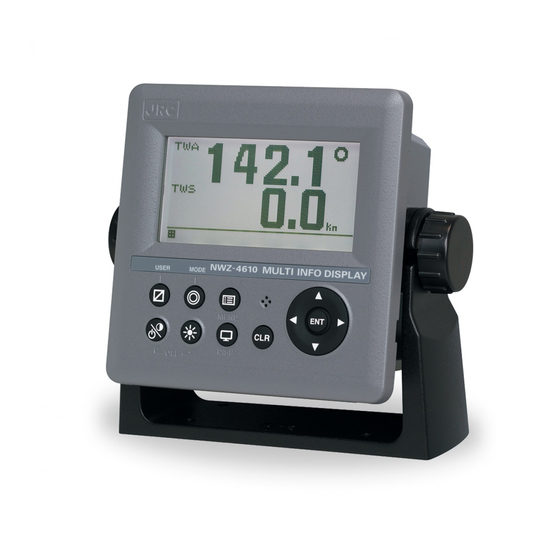
- Page 1 NWZ-4610 NWZ-4610 MULTI INFORMATION DISPLAY MULTI INFORMATION DISPLAY INSTRUCTION INSTRUCTION MANUAL MANUAL...
- Page 3 General Information Thank you for purchasing the Japan Radio Co., Ltd. NWZ-4610 Multi Information Display (MID). This equipment receives NMEA data from various sensors for display. Before attempting to operate this equipment, read this instruction manual thoroughly to ensure correct and safe operation in accordance with the warning instructions and operation procedures.
-
Page 4: Before You Begin
Before You Begin Symbols Used In This Manual In this manual, and on the equipment, we use several warning signs to call your attention to important items that, if not handled correctly, could present danger to yourself or property. These warning note classifications are as described below. Please be fully aware of the importance of these items before using this manual. -
Page 5: Usage Hints
Usage Hints WARNING Do not remove the cover of this unit. Otherwise, you may touch a high-voltage part and suffer from an electric shock. Turn off the power on/off switch, and turn off the power supply breaker when you for maintenance check this unit for maintenance. - Page 6 CAUTION Without qualified service personnel, do not attempt to install this unit. Contact our service center or agent for any electrical work or installation of this unit. Otherwise it may cause a malfunction. Do not install this unit at the place exposed to direct sunlight for a long time or hit by hot wind or where the temperature rises above 55℃.
-
Page 7: External View
External View... -
Page 8: Table Of Contents
Contents General Information ........................i Before You Begin .......................... ii Usage Hints ..........................iii External View ..........................v Chapter 1 Introduction ......................1-1 1.1. Function ..........................1-1 1.2. Features ..........................1-2 1.3. Components ......................... 1-3 1.3.1. Standard equipment ....................... 1-3 1.3.2. - Page 9 4.9.1. Changing to a maintenance mode ................4-33 4.9.2. Setting a model ......................4-34 4.9.3. Selecting a dimmer unit ....................4-34 4.9.4. Dimmer linked control and data sharing with RS-485 ..........4-35 4.9.5. Setting a serial port ...................... 4-38 4.9.6. Setting a contact port ....................
-
Page 11: Chapter 1 Introduction
Chapter 1 Introduction 1.1. Function The Multi Information Display (MID) is the display unit that receives NMEA data items from various sensors to display them. The screen can be split to up to 4 areas for use. Only necessary information can be displayed by selecting data to be displayed in the areas. -
Page 12: Features
1.2. Features NWZ-4610 Multi Information Display (MID) has the following features: 1) Display of various NMEA data items 2) Selection of display contents and screen layout 3) Distribution of power supply in daisy chain mode 4) Selection of display screen in each mode... -
Page 13: Components
The standard equipment and options are shown in the tables below. 1.3.1. Standard equipment Description Model No. CODE Remarks DISPLAY NWZ-4610 NWZ-4610 Main Body 14 cores 2 m/ With Fuse holder DATA POWER CABLE CFQ-5766A CFQ5766A data, power, contact FUSE... -
Page 14: Construction
1.4. Construction Display NWZ-4610 Unit: mm Mass: Approximately 0.8kg Figure 1.2 NWZ-4610 OUT LINE (Disk Form type) -
Page 15: System Configuration
CFQ-5769 3m CFQ-5769 3m RS-485 External device Daisy chain CFQ-5767 CFQ-5769 Sensors CFQ-5768 3m SENSOR/DATA2 DATA1 SENSOR/DATA2 DATA1 NWZ-4610 NWZ-4610 DC12/24V DATA DC12/24V DATA CFQ-5766A External device * 250V-TTYCS-1 3 ports Sensors Junction Dimmer unit CQD-10 *250V-TTYCS-1 Max 15 m... -
Page 17: Chapter 2 Names And Functions Of The Components
Chapter 2 Names and Functions of the Components Display Buzzer Operation panel Figure 2.1 Operation panel of main display unit Keys Name Functions Power/ Turns on the power. This key also adjusts the screen contrast. Contrast key The power is turned off when the key and this key are pressed at the same time. - Page 18 Reading the Display Numeric display screen U: UTC Date and time L: Local time If date and time data is not received, "-" is displayed. Screen title Ship speed and direction Display area Status bar Screen number Freeze indicator The display mode and the screen number During operation, the black part moves.
- Page 19 Wind direction/wind velocity screen The left and right keys can be used to switch between true and relative. True wind direction Wind direction True wind Arrow from velocity windward Special screen for JFE-380/680 1) Single Transducer Display mode Position of Transducer Offset Depth Range...
- Page 20 COG screen When the COG is invalid, "---.-" is displayed.
-
Page 21: Chapter 3 Display Screen
Chapter 3 Display Screen 3.1. Display Screen The screen is switched each time the key is pressed. Up to six screens can be displayed. The screen after the power is turned on becomes the screen when it is turned off. When the key is pressed, the mode is switched. - Page 22 Split screen display The screen can be split into 1 to 4 areas to display multiple information items. 1-split screen 2-split screen 3-split screen 4-split screen Enlarged part display Integer part or decimal can be highlighted. Enlarged integer part screen Enlarged decimal part screen...
-
Page 23: Chapter 4 Operation
Chapter 4 Operation WARNING Do not place a vessel containing water, etc. or a metallic object on this unit. When water spills or when water or the object enters the unit, a fire, an electric shock, or a failure may occur. Do not use this unit at a voltage other than the supply voltage stated on the unit. -
Page 24: Menu
4.1. Menu Normal menu Main menu Sub menu Range remarks DISPLAY CONTRAST 1-13 4.5.1 DIMMER MAXIMUM 4-13 4.5.2 DIMMER TYPICAL 3-12 4.5.2 DIMMER MINMUM 2-11 4.5.2 CLICK SOUND ON/OFF 4.5.3 MODE1 4.5.4.1 DISPLAY1 4.5.4.2 SEGMENTATION1 4.5.4.3 DISPLAY 4.5.4.4 LAT/LON/HDG/ROT/COG/ OWN SHIP 4.5.4.4 SOG/PITCH/ROLL/HEAVING/ WATER TEMP/TWA/TWS/AWS/... - Page 25 Main menu Sub menu Range remarks AUTO SCREEN ON/OFF 4.5.4.4 SOUND SOUND1/SOUND2/OFF 4.5.4.4 TIME 1-10sec 4.5.4.4 GRAPHIC 4.5.4.3 WIND/ DEPTH/WATER TEMP/ DISPLAY 4.5.4.4 SPEED1/SPEED2/RUDDER AUTO SCREEN ON/OFF 4.5.4.4 SOUND SOUND1/SOUND2/OFF 4.5.4.4 TIME 1-10sec 4.5.4.4 4.5.4.3 DISPLAY2 Same as DISPLAY1 4.5.4.2 DISPLAY3 Same as DISPLAY1 4.5.4.2...
- Page 26 Main menu Sub menu Range remarks LCD COLOR ON/OFF 4.8.11 UNDER 4.8.3 UNDER 0-99.9kn 4.8.3 SOUND ON/OFF 4.8.11 LCD COLOR ON/OFF 4.8.11 IN RANGE 4.8.3 MAXIMAUM 0-99.9kn 4.8.3 MINIMUM 0-99.9kn 4.8.3 SOUND ON/OFF 4.8.11 LCD COLOR ON/OFF 4.8.11 OUT RANGE 4.8.3 MAXIMAUM 0-99.9kn...
- Page 27 Main menu Sub menu Range remarks SOUND ON/OFF 4.8.11 LCD COLOR ON/OFF 4.8.11 WIND OVER/OFF 4.8.7 OVER 4.8.7 OVER 99.9kn 4.8.7 SOUND ON/OFF 4.8.11 LCD COLOR ON/OFF 4.8.11 OVER/UNDER/IN RANG/OUT AIR TEMP 4.8.8 RANG/OFF OVER 4.8.8 OVER 4.8.8 -99.9 - +99.9C SOUND ON/OFF 4.8.11...
- Page 28 Main menu Sub menu Range remarks MAXIMAUM 0 – 99.9 % 4.8.10 MINIMUM 0 – 99.9 % 4.8.10 SOUND ON/OFF 4.8.11 LCD COLOR ON/OFF 4.8.11 OUT RANGE 4.8.10 MAXIMAUM 0 – 99.9 % 4.8.10 MINIMUM 0 – 99.9 % 4.8.10 SOUND ON/OFF 4.8.11...
- Page 29 Main menu Sub menu Range Reference/remarks 4.9.4.4 SENTENCE Sentence list 4.9.4.4 SEND only BIT RATE 38400/57600/76800/115200 4.9.4.4 CONTACT INPUT DIMMER/ACK 4.9.6.1 200PULSE/NM/ CONTACT OUTPUT 400PULSE/NM/ 4.9.6.2 DIAGNOSIS CONFIG OUT/ERROR LOG OUT 4.9.7/4.9.15 MAINTENANCE INPUT DATA 4.9.9 DIAGNOSIS 4.9.10 DISPLAY DIAG 4.9.10 MONITOR TEST 4.9.10...
-
Page 30: Basic Operation
4.2. Basic Operation 4.2.1. Turning on the power When the main power is turned on, the power to the display unit is automatically turned on. In the state in which the power is turned off by the display unit key operation, pressing the turns on the power. -
Page 31: Starting (Abnormal)
4.2.3. Starting (Abnormal) If the self-diagnosis results are errors “NG,” the results are displayed as follows. Caution When any abnormality (NG) is found, contact JRC or one of our agents. 4.2.4. Starting (Abnormal) When the program is corrupted, the following screen is displayed. Turn off the power and contact JRC or one of our agents. -
Page 32: Adjusting The Back Light (Lighting) By Using The Key
4.2.6. Adjusting the back light (lighting) by using the key The brightness of display and operation panel backlight can be set to one of four levels (bright, medium, dark, off). Whenever is pressed, the level changes in the order of bright – medium – dark – off –dark – medium –... -
Page 33: Selecting Items From The Menus
4.2.11. Selecting items from the menus This section shows the procedure for selecting items from the menus and determining the selection. Procedure Move the cursor to a required item by using and press . The item is selected and a submenu is opened to enable selection of details. -
Page 34: Entering A Numeric Value
4.2.12. Entering a numeric value This section describes the procedure for entering a numeric value. Procedure Move the cursor to the field in which a value is to be entered by using Set a numeric value to be entered by using and press Move the cursor to the right most field and press . -
Page 35: User Mode Change
4.3. User Mode Change The user mode can be changed. Up to three user modes are available, and six screens can be registered in one mode. For details about how to register the screens in each mode, refer to “4.5.4 Setting a display screen”. Procedure Press the key. -
Page 36: Setting Display
4.5. Setting Display When “Display” is selected on the main menu, a display menu is displayed. On the display menu, LCD (contrast and back light), click sound, screen selection, and back light color can be set. Continued Each submenu is outlined below. 1) LCD: Adjusts the contrast and sets the back light level. -
Page 37: Adjusting Back Light
4.5.2. Adjusting back light Brightness can be changed by using . Four levels of brightness are available, bright, medium, dark, and off. This section shows how to set a level value of each brightness. Procedure Display a main menu by pressing Select “DISPLAY”, “LCD”, and “DIMMER MAXIMUM/TYPICAL/MINIMUM”... - Page 38 4.5.4.1. Selecting User Mode MID can set up to three user modes. Up to six screens can be registered in each mode, and up to 18 screens can be registered. Press the key to change the set user mode. User mode 1 User mode 2 User mode 3 or automatic...
- Page 39 4.5.4.2. STEP1 Selecting a display screen Up to six display screens can be registered in this display unit. or automatic Procedure Display a main menu by pressing (normal mode). Press the key to select “DISPLAY,” “MODE1,” “MODE2,” or “MODE3” in order, and press key to select the user mode.
- Page 40 4.5.4.3. STEP2 Selecting a screen structure The screen structures of each display screen include customized screens that can be set freely, special screens that do not allow any setting, and graphic screens. Select a screen structure. When display structure selection is set to “OFF”, the display screen cannot be registered. Customized screen One screen can be segmented into screens 1 to 4.
- Page 41 4.5.4.4. SETP3 Selecting display contents Select as many display contents as the number of screens that are created by segmentation. For instance, for a 2-segmentation screen, select the display content for one half of the screen and then select the display content for the other half of the screen (see the diagram below). The display content of a customized screen is divided according to the category.
- Page 42 Select a display content Select a category and press Select a category by using Select display contents by using and press Go to procedure 6 when setting an auto screen. Fixed screen and graphic screen Select “DISPLAY” by using and press Select display contents by using and press Go to procedure 6 when setting an auto screen.
-
Page 43: Selecting A Back Light Color
Select “TIME” by using Enter a switching time by using and press Starting an auto screen Switching the USER MODE to use an auto screen function Press and hole for 1 second or more. Stopping an auto screen Press any keys except Setting a display mode The display mode can be set only with segmentaion1 screen. -
Page 44: Setting Graph Scale
4.5.6. Setting graph scale The vertical axis and horizontal axis scale of the water temperature and water depth graphs can be set. For detail screen, refer to page 2-2. Horizontal axis setting TIME: The maximum display time of the horizontal axis is set. The time that can be set is 5 minutes, 10 minutes, 20 minutes, and 30 minutes. -
Page 45: System Settings
4.6. System Settings Select “SYSTEM” on the main menu to display the system settings screen. To change the system settings, place the unit in maintenance mode. An overview of each submenu is as follows. 1) UNIT: Set the units of distance/ship speed, temperature, water depth, and wind velocity. 2) TIME DIFF: Set the time difference between UTC and local time. -
Page 46: Setting The Time Difference
4.6.2. Setting the time difference You can set the time difference between UTC and local time. For Japan, the time difference is +9 hours, so you would input +09:00. When a time difference is set, “L” is displayed on the upper right of the screen. Procedure Refer to “4.9.1 Changing to a maintenance mode”... -
Page 47: Setting Date Display Format
4.6.3. Setting date display format You can set the date display format to “DD MMM,'YY,” “MMM DD,'YY,” or “'YY-MMM-DD.” YY: Year MMM: Month DD: Day Procedure Refer to “4.9.1 Changing to a maintenance mode” to display the maintenance menu. Press the key to select “SYSTEM,”... -
Page 48: Setting Water Depth Offset Of Depth Sounder
4.6.6. Setting water depth offset of depth sounder You can set an offset in the received water depth value. The offset that can be set is ±99.9 m. When an offset is set, the received water value with the offset value added is displayed. Procedure Refer to “4.9.1 Changing to a maintenance mode”... -
Page 49: Language Settings
4.7. Language Settings You can set the display language to nine languages (English/Japanese (katakana)). To change the language, place the unit in the maintenance mode. A maximum of nine languages: Other than English / Japanese, it is due to add one by one. Procedure Refer to “4.9.1 Changing to a maintenance mode”... -
Page 50: Setting The Alarm Range
4.8.1. Setting the alarm range An alarm occurs when the range is set and the value matches the set range. You can select the range from OVER, UNDER, IN RANGE, and OUT RANGE depending on the alarm. OVER: An alarm occurs when the value exceeds the set value. UNDER: An alarm occurs when the value falls below the set value. -
Page 51: Setting A Vessel Speed Alarm
4.8.3. Setting a vessel speed alarm When the vessel speed reaches the set range, the alarm is issued. The range can be selected from OVER, UNDER, IN RANGE, and OUTRANGE. OVER: An alarm is issued when the vessel speed reaches or exceeds the set speed. UNDER: An alarm is issued when the vessel speed is equal to or slower than the set speed. -
Page 52: Setting The Water Temperature Alarm
4.8.5. Setting the water temperature alarm An alarm occurs when the water temperature exceeds the set value. Procedure Refer to “4.9.1 Changing to a maintenance mode” to display the maintenance menu. Press the key to select “ALARM” and “WATER TEMP” in order. Press the key to select “OVER,”... -
Page 53: Setting The Air Temperature Alarm
4.8.8. Setting the air temperature alarm An alarm occurs when the air temperature exceeds the set value. Procedure Refer to “4.9.1 Changing to a maintenance mode” to display the maintenance menu. Press the key to select “ALARM” and “AIR TEMP” in order. Press the key to select “OVER,”... -
Page 54: Setting A Buzzer Sound And Screen Back Light
4.8.11. Setting a buzzer sound and screen back light An alarm sound and the color of the screen back light at the occurrence of an alarm can be set. When the back light color under the normal condition is set to white, the color is changed to orange and when the back light color is set to orange, the color is changed to white. -
Page 55: Setting Installation
4.9. Setting Installation After completing the installation that is described in Chapter 6, check the operation and set the details. In the installation setting, implement the following operations according to the system specification of the vessel. 1) Changing to a maintenance mode 2) Setting a model 3) Selecting a dimmer unit 4) Setting dimmer control linkage and data sharing... -
Page 56: Setting A Model
4.9.2. Setting a model This display unit is set in the MID display unit. When the model is set, the setting contents are initialized. Procedure Refer to “4.9.1 Changing to a maintenance mode” to display the maintenance menu. Select “DISPLAY TYPE” by using and press Select “MID”... -
Page 57: Dimmer Linked Control And Data Sharing With Rs-485
4.9.4. Dimmer linked control and data sharing with RS-485 By connecting display units with RS-485 network, dimmer control can be linked and data can be shared. To connect display units with RS-485 network, the display units must be identified by setting RS-485ID in each display unit. - Page 58 4.9.4.1. Setting RS-485ID To identify a display unit on the RS-485 network, set an ID for each display unit. To use RS-485, an ID must be set. Avoid duplication of ID among the display units. Otherwise, data and dimmer linkage are not possible. Available IDs are from 1 to 10.
- Page 59 4.9.4.4. Sharing data Data can be shared among the display units that are connected through the RS-485 network. Set the data to be transmitted. Although setting for reception is not necessary, the baud rate must be standardized among the display units. For the linkage, set RS-485ID by referencing “4.9.4.1 Setting RS-485ID”.
-
Page 60: Setting A Serial Port
Return control to the BIT RATE selection screen and select BIT RATE by using Available bit rates are “38400”, “57600”, “76800”, and “115200”. Normally, “115200” is recommended. Caution Since data is transmitted between display units, some time lag occurs at the switching of display. - Page 61 4.9.5.1. Setting transmission The procedure for setting a serial port for transmission is shown below. Procedure Setting port Select an output format Select SEND Select VERSION (NMEA only) BIT RATE selection screen Select BIT RATE Select an output sentence Sentence list Select an output cycle Refer to “4.9.1 Changing to a maintenance mode”...
- Page 62 Selecting IEC For IEC, there is no need to select VERSION. Select “SEND” from “DATA IN/OUT” by using Select an output sentence by using and set an output cycle. The cycle can be selected within the range from 1 second to 9 seconds and when OFF is selected, the sentence is not output.
- Page 63 4.9.5.2. Setting reception In the reception setting, set a bit rate. There is no need to set a sentence or a cycle. Procedure Setting port Select an output format Select RECEIVE Select BIT RATE Refer to “4.9.1 Changing to a maintenance mode” to display the maintenance menu. Select “INTERFACE”...
-
Page 64: Setting A Contact Port
4.9.6. Setting a contact port 4.9.6.1. Setting a contact input port A contact input port can be set to the following input. 1) DIMMER: Use this option when connecting an external dimmer unit. 2) ACK: Alarm ACK is input from an external unit. To use an external dimmer unit, the dimmer unit must be set to “EXT DIMMER”. -
Page 65: Outputting Alarm History
4.9.7. Outputting alarm history Alarm history can be output to an external unit. Data is output from a data IN/OUT1 port. If data IN/OUT1 is set to reception, the port must be set to transmission. Connect PC to a serial port before output operation. Procedure Refer to “4.9.1 Changing to a maintenance mode”... -
Page 66: Checking The Input Port
4.9.9. Checking the input port Data that is received from the input port can be displayed on a screen. The input port and display format (ASCII/BINARY) can be selected. Data of the port that is set to output cannot be displayed. Procedure Refer to “4.9.1 Changing to a maintenance mode”... -
Page 67: Displaying An Alarm
4.9.11. Displaying an alarm The current alarm and past alarms can be displayed. Up to 40 past alarms can be stored and when the number of alarms exceeds 40, alarms are deleted from the oldest one. Procedure Refer to “4.9.1 Changing to a maintenance mode” to display the maintenance menu. Select “MAINTENANCE”... -
Page 68: Displaying The Software Version
4.9.12. Displaying the software version The software version, serial number and bar code number of the display unit can be displayed. Procedure Refer to “4.9.1 Changing to a maintenance mode” to display the maintenance menu. Select “MAINTENANCE”, “SOFT VERSION”, and “DISPLAY VER” in this order by using Software version Serial number Bar code number... -
Page 69: Demonstration
4.9.14. Demonstration Through a demonstration, display and external output are enabled in the same way as the actual equipment operation. Procedure Refer to “4.9.1 Changing to a maintenance mode” to display the maintenance menu. Select “DEMO MODE” and “DEMO TYPE” in this order by using Select a DEMO condition and press Select "DEMO MODE"... -
Page 70: 4.10. Setting Daisy Chain
4.10. Setting daisy chain The power can be distributed to up to three units from one power supply by setting daisy chain. The display units in the same dimmer group can share the dimmer. Power is not supplied to the fourth and subsequent units. ON: Power is supplied to the next MID for daisy-chaining. -
Page 71: Chapter 5 Maintenance
Chapter 5 Maintenance WARNING Do not check or repair in this unit. Please call our field representative or your nearest JRC office for inspection and repair services. Otherwise it may cause a fire or an electric shock. Do not remove the cover of this unit. Otherwise, you may touch a high-voltage part and suffer from an electric shock. -
Page 72: Daily Maintenance
5.1. Daily Maintenance WARNING Do not remove the cover of this unit. Otherwise, you may touch a high-voltage part and suffer from an electric shock. Turn off the power on/off switch, and turn off the power supply breaker when you check this unit for maintenance.」 「an electric shock. -
Page 73: Alarm
5.2. Alarm Refer to "4.9.11 Displaying an alarm" and check if any alarm is given or not. If it is, check the details referring to the list shown below. Alarm List Message Message Contents Alarm Causes Number 2/3/7 SOG/STW/SOG(LOG) Speed alarm occurs TRIP Trip alarm occurs WATER TEMP... -
Page 74: Troubleshooting For Malfunctions Or Abnormalities
5.3. Troubleshooting for Malfunctions or Abnormalities WARNING In the event that smoking or burning odors are detected, immediately terminate operation of the unit and contact your sales agent outlet or one of JRC branch offices, sales centers or liaison offices. Never attempt to check or repair the unit. Continuing operation may cause a fire or an electric shock. -
Page 75: Repair Unit
5.4. Repair Unit 5.4.1. Repair unit Repair units and their models are shown below. Name Model Notes DSP UNIT CMJ-562 POWER UNIT CMP-490 LCD UNIT CCN-423 FUSE Name Model Notes for Data power cable FUSE MF60NR 250V 1 1A FUSE Mechanical Parts Name Code... -
Page 77: Chapter 6 Installation
Chapter 6 Installation CAUTION Consult with JRC or our agents to install. Installation by unauthorized personnel may result in a malfunction. Do not install this unit at the place exposed to direct sunlight for a long time or hit by hot wind or where the temperature rises above 55℃. -
Page 78: Affixing Display Unit Nameplate Labels
6.1. Affixing Display Unit Nameplate Labels 6.1.1. Affixing product nameplate Peel the label of the equipment to be used from the accessory product nameplate, and affix it to the center of the front panel. Product Nameplate (Accessory) Display Unit Front 6.1.2. -
Page 79: Display Unit Installation
6.2. Display Unit Installation 6.2.1. Selecting the position for installation WARNING Install this unit at least 1 m away from any magnetic compasses. Installation near a magnetic compass may interfere with the magnetic compass, resulting in an accident. Do not use this unit at the voltage other than its rated voltage. Otherwise it may result in a fire, an electric shock or a failure. -
Page 80: Mounting The Display Unit Using A Rack
6.2.2. Mounting the display unit using a rack Use the following procedure. (1) Fix the desktop rack at the required installation position by using the mounting screws (φ4~6 screw or wood screw, L>=15mm, provided by the shipyard). (2) Insert the front panel into the main unit. (3) Attach the rotational washer on the side of the main unit. - Page 81 285 or more 190 or more Required installation space Mount (bottom) (Unit: mm)
-
Page 82: Mounting Using A Flash Mount
6.2.3. Mounting using a flash mount Use the following procedure. See the diagram below for the mounting space and mounting holes. Do not tighten a screw too much. Doing so may result in damage of installation holes. (1) Insert the main unit in the installation location (2) Fix the main unit using the mounting screws (φ4 screw or wood screw, L>=10mm, provided by the shipyard). - Page 83 Provide maintenance space or more (Square hole) Mounting hole ※About the corner C11, (Screw pitch) may want to cut φ25...
-
Page 84: Removing The Display Unit By Flash Mounting
6.2.4. Removing the display unit by flash mounting Use the following procedure to remove the display unit. (1) Insert a hexagonal wrench into the holes (2) at the bottom of the front panel. (2) Remove the front panel by pressing down the hexagonal wrench. Mounting wall Front panel Press down... -
Page 85: Cable Connection
6.3. Cable Connection Unit (Rear Connector) [DATA 1] [SENSOR/DATA 2] Share data between display units Daisy chaining [TERM.] Or, connect with external device. Turn ON and OFF terminal resistance DATA1 connection [DC12/24V DATA] Power Input Terminal Used fro power input to unit. Be sure to connect specified data power cable. -
Page 86: Dc12/24V Data Connector
6.3.1. DC12/24V DATA connector Display Unit Rear: Connector Pin Number 14 13 12 11 10 表示器 背面 Fuse Holder (Containing 1A Fuses) Black CFQ5766 Data Power Cable CFQ-5766A: 2 m (Accessory) CFQ-5766D: 10 m (Option) CFQ-5766F: 20 m (Option) Terminal Number Name Explanation (CFQ-5766) - Page 87 [Input/Output Condition for Serial Transmission] The data power cable (CFQ-5766) has three serial transmission channels. The input/output settings for DATA I/O "1" and "2" are linked to each other. As listed below, four connections and settings can be made. For the input/output settings for channels, see "4.9.5 Setting a serial port". Data Power Cable CFQ-5766A: 2 m (Accessory)
- Page 88 [Input/Output Circuit] NWZ-4610 Display Unit [Contact Output] Relay 3: Orange 4: Yellow 5: Green Contact maximum 30 VDC/1.0 A [Contact Input/Analog Input] NCM-227 Dimmer Unit 6: Blue 7: Purple or Contact Connection [Serial Transmission] IEC61162-1 (NMEA) Output Setting SD-A Input...
-
Page 89: Data1 Connector
6.3.2. DATA1 connector TERM. Switch Display Unit Rear: Connector Pin Number Display Unit Rear CFQ5769 Data Cable CFQ-5769: 3 m (Option) Terminal Name Explanation Number (CFQ-5769) Brown SD1-A Serial Connect to the display unit for serial transmission Transmission SD1-B (RS-484) Green SD1-C Shield... - Page 90 [T-SHAPED CONNECTOR] This T-SHAPED CONNECTOR can be used to extend cables and connect multiple units (up to 10 units). CFQ-5769 CFQ-5769 T-SHAPED CONNECTOR (option) Type name: AA-040404-MMM-TL Code: 5JCDX00071 CFQ-5769 [To Extend the Cable] CFQ-5769: 3 m x necessary number of cables T-SHAPED CONNECTOR Same number as CFQ-5769 CFQ-5769: 3 m...
- Page 91 [To Connect Multiple Units] Up to 10 units can be connected. The number of cables and the number of T-SHAPED CONNECTOR vary depending on the distance between display units. CFQ-5769: 3 m CFQ-5769: 3 m CFQ5768 CFQ5768 ... 3 . 4 . 5 . 6 . 7 . 8 . 9 ... Term.: ON (up) Term.: OFF (down) Term.: ON (up)
- Page 92 [To Group Dimmer Control] The following shows an example of grouping 10 units (maximum number of connections) into 3 units, 3 units, and 4 units. CFQ-5769: 3 m RS485ID:01 RS485ID:02 RS485ID:03 12.3 12.3 12.3 Dimmer group: 01 Dimmer: Key Key operation RS485ID:06 RS485ID:05 RS485ID:04...
-
Page 93: Sensor/Data2 Connector
6.3.3. SENSOR/DATA2 connector [For serial communication with external device] Display Unit Rear: Connector Pin Number Display Unit Rear CFQ5767 Data cable CFQ-5767: 3 m (option) Terminal Name Explanation Number Unused White Serial RXD2-B Input to the specification set by “DATA IN/OUT4.” transmission Green RXD2-A... - Page 94 Brown TXD2-B DATA OUT 4 Water temperature/ Output current Display Unit Rear Output together from this port DATA IN 1 NWZ-4610 DATA IN 2 display unit DATA OUT 4 DATA IN 3 DATA IN 4 CFQ5766 Terminal Name Setting Example...
- Page 95 [To daisy-chain the units] Display Unit Rear: Connector Pin Number Display Unit Rear CFQ5768 Data cable CFQ-5768: 3 m (option) Terminal Name Example Number (CFQ-5768) Power supply DCOUT+ Supplies the power to the subsequent display unit. Black output DCOUT- White Serial RXD2-B transmission...
- Page 96 Up to three units can be daisy-chained. To make this connection, set the daisy-chain setting to ON. Display Unit Rear Data power cable CFQ: 5768: 3 m (option) Data power cable 14 pins CFQ-5768: 3 m (option) 6 pins Power supply CFQ5766...
-
Page 97: Optional Peripheral Connection
The brightness of the backlight can be changed at a location away from the display unit by connecting the dimmer unit (NCM-227). To calibrate the external dimmer unit, refer to "7.1 Calibration of External dimmer unit "in service manual. DATA1 NWZ-4610 Display Unit SENSOR /DATA2 DC12/24V DATA... - Page 98 6-22...
-
Page 99: Chapter 7 After-Sales Service
Chapter 7 After-Sales Service 7.1. When Ordering a Repair When a failure has been detected, stop operation and contact the dealer or agent from which you purchased the device or one of our branches, marketing offices, and representative offices. Repair during warranty period Should a malfunction occur when the unit has been operated according to descriptions and instructions in the instruction manual, it will be repaired free of charge. -
Page 101: Chapter 8 Disposal
Chapter 8 Disposal 8.1. Disposal of the Equipment Observe all local laws and regulations when disposing of those units. The battery is not used for those units. -
Page 103: Chapter 9 Specifications
Chapter 9 Specifications 1) Basic Display Unit: 4.5 inch monochrome LCD 128 64 dots Backlight: White LED or orange LED (selectable) Dimmer Levels: 4 levels (Bright, Medium, Dark, OFF) Dimmer control: Key or external dimmer unit ... - Page 104 3) Interface (1) Serial Transmission Channel Specification Notes DATA IN/OUT1 RS-422 Input or Output NMAE, IEC DATA IN/OUT2 RS-422 Input or Output NMEA, IEC DATA IN/OUT3 RS-422 Input or Output NMEA, IEC DATA IN/OUT4 RS-422 Input or Output NMEA, IEC Daisy chain RS-485 RS-485...
-
Page 105: Appendix
Appendix Appendix 1 Outline and Setting Drawing (1) NWZ-4610 MAIN DISPLAY (Desk form type) Appendix-1... - Page 106 (2) NWZ-4610 MAIN DISPLAY (Console mount type) Appendix-2...
-
Page 107: Appendix 2 Default Value
Appendix 2 Default value Normal menu Main menu Sub menu Default remarks DISPLAY CONTRAST DIMMER MAXIMUM DIMMER TYPICAL DIMMER MINMUM CLICK SOUND MODE1 DISPLAY1 SEGMENTATION1/DOPPLER/STW DISPLAY MODE NORMAL AUTO SCREEN SOUND TIME 1sec DISPLAY2 SEGMENTATION1/OWN SHIP/SOG DISPLAY MODE NORMAL AUTO SCREEN SOUND TIME 1sec... - Page 108 Main menu Sub menu Default remarks AUTO SCREEN SOUND TIME 1sec DISPLAY4 GRAPHIC/SPEED1 DISPLAY MODE NORMAL AUTO SCREEN SOUND TIME 1sec DISPLAY5 SEGMENTATION1/OWN SHIP/HDG DISPLAY MODE NORMAL AUTO SCREEN SOUND TIME 1sec DISPLAY6 SEGMENTATION1/OWN SHIP/ROT DISPLAY MODE NORMAL AUTO SCREEN SOUND TIME 1sec...
- Page 109 Main menu Sub menu Default remarks WATER TEMP TIME 10min +30C 0C USER DISPLAY SYSTEM UNIT DIST/SPD NM, kn C/ TEMP DEPTH WIND TIME DIFF +00:00 DATE DISP TIME DISP DD MMM,’YY HH:MM / LORAN C LORAN C 4990 TD1 CORR +0.0 TD2 CORR +0.0...
- Page 110 Maintenance menu Main menu Sub menu Default remarks DAISY CHAIN INTERFACE DATA I/O DATA IN/OUT1 NMEA DATA IN/OUT RECEIVE VERSION SENTENCE BIT RATE 4800 DATA IN/OUT2 NMEA DATA IN/OUT RECEIVE VERSION SENTENCE BIT RATE 4800 DATA IN/OUT3 NMEA DATA IN/OUT RECEIVE VERSION SENTENCE...
-
Page 111: Appendix 3 Setting Value Memo
Appendix 3 Setting value memo Normal menu Main menu Sub menu Setting value DISPLAY CONTRAST 1 2 3 4 5 6 7 8 9 10 11 12 13 DIMMER MAXIMUM 4 5 6 7 8 9 10 11 12 13 DIMMER TYPICAL 3 4 5 6 7 8 9 10 11 12 DIMMER MINMUM... - Page 112 Main menu Sub menu Setting value MODE3 DISPLAY1 DISPLAY2 DISPLAY3 DISPLAY4 DISPLAY5 DISPLAY6 SEGMENT1 SEGMENT1 SEGMENT1 SEGMENT1 SEGMENT1 SEGMENT1 SEGMENT2 SEGMENT2 SEGMENT2 SEGMENT2 SEGMENT2 SEGMENT2 SEGMENT3 SEGMENT3 SEGMENT3 SEGMENT3 SEGMENT3 SEGMENT3 SEGMENT4 SEGMENT4 SEGMENT4 SEGMENT4 SEGMENT4 SEGMENT4 GRAPHIC GRAPHIC GRAPHIC GRAPHIC GRAPHIC GRAPHIC...
- Page 113 Main menu Sub menu Setting value SOUND ON/OFF LCD COLOR ON/OFF SPEED OVER/UNDER/IN RANG/OUT RANG/OFF OVER UNDER MAXIMUM MINIMUM SOUND ON/OFF LCD COLOR ON/OFF TRIP OVER/OFF OVER SOUND ON/OFF LCD COLOR ON/OFF WATER TEMP OVER/UNDER/IN RANG/OUT RANG/OFF OVER UNDER MAXIMUM MINIMUM SOUND ON/OFF...
- Page 114 Maintenance menu Main menu Sub menu Setting vlaue DAISY CHAIN ON/OFF INTERFACE DATA I/O DATA IN/OUT1 NMEA DATA IN/OUT SEND/RECEIVE VERSION 1.5/2.1/2.3/4.0 SENTENCE DATA IN/OUT1 SENTENCE BIT RATE 4800/9600/19200/38400 DATA IN/OUT SEND/RECEIVE SENTENCE DATA IN/OUT1 SENTENCE BIT RATE 4800/9600/19200/38400 DATA IN/OUT1 SENTENCE CUR: BDK: DBS:...
- Page 115 Main menu Sub menu Setting vlaue BIT RATE 4800/9600/19200/38400 SENTENCE DATA IN/OUT4 SENTENCE BIT RATE 4800/9600/19200/38400 DATA IN/OUT4 SENTENCE CUR: BDK: DBS: DBT: DPT: GGA: GLL: GNS: HDG: HDM: HDT: MDA: MHU: MMB: MTA: MTW: MWV: RMC: ROT: RPM: RSA: THS: VBW: VDR:...
- Page 116 Appendix-12...
- Page 117 有毒有害物质或元素的名称及含量 (Names & Content of toxic and hazardous substances or elements) 形式名 : NWZ-4610 名称 : Multi Information Display (MID) (Type) (Name) 有毒有害物质或元素 (Toxic and Hazardous Substances and Elements) 部件名称 (Part name) 铅 汞 镉 六价铬 多溴联苯 多溴二苯醚 (Pb)
- Page 120 For further information,contact: Not use the asbestos http://www.jrc.co.jp Marine Service Department Telephone : +81-3-3492-1305 Facsimile : +81-3-3779-1420 e-mail : tmsc@jrc.co.jp AMSTERDAM Branch Telephone : +31-20-658-0750 Facsimile : +31-20-658-0755 e-mail : service@jrceurope.com SEATTLE Branch Telephone : +1-206-654-5644 Facsimile : +1-206-654-7030 e-mail : marineservice@jrcamerica.com CODE No.7ZPNA4284 CODE No.7ZPNA4284...
Need help?
Do you have a question about the NWZ-4610 and is the answer not in the manual?
Questions and answers