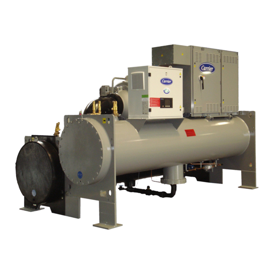
Carrier AquaEdge 19XRV series Operation, Maintenance And Installation Manual
Single-stage or two-stage
semi-hermetic centrifugal liquid chillers
with pic iii controls and hfc-134a
50/60 hz
Hide thumbs
Also See for AquaEdge 19XRV series:
- Start-up, operation and maintenance instructions manual (160 pages) ,
- Installation instructions manual (76 pages) ,
- Start-up and service instructions (40 pages)
Table of Contents
Advertisement
Quick Links
Start-Up, Operation, and Maintenance Instructions
SAFETY CONSIDERATIONS
Centrifugal liquid chillers are designed to provide safe
and reliable service when operated within design specifi-
cations. When operating this equipment, use good judg-
ment and safety precautions to avoid damage to
equipment and property or injury to personnel.
Be sure you understand and follow the procedures and
safety precautions contained in the chiller instructions
as well as those listed in this guide.
DANGER
Failure to follow these procedures will result in severe per-
sonal injury or death.
DO NOT VENT refrigerant relief valves within a building.
Outlet from rupture disc or relief valve must be vented out-
doors in accordance with the latest edition of ANSI/
ASHRAE 15 (American National Standards Institute/
American Society of Heating, Refrigerating, and Air-Con-
ditioning Engineers). The accumulation of refrigerant in an
enclosed space can displace oxygen and cause
asphyxiation.
PROVIDE adequate ventilation in accordance with ANSI/
ASHRAE 15, especially for enclosed and low overhead
spaces. Inhalation of high concentrations of vapor is harm-
ful and may cause heart irregularities, unconsciousness, or
death. Misuse can be fatal. Vapor is heavier than air and
reduces the amount of oxygen available for breathing.
Product causes eye and skin irritation. Decomposition
products are hazardous.
DO NOT USE OXYGEN to purge lines or to pressurize a
chiller for any purpose. Oxygen gas reacts violently with
oil, grease, and other common substances.
NEVER EXCEED specified test pressures, VERIFY the
allowable test pressure by checking the instruction litera-
ture and the design pressures on the equipment nameplate.
DO NOT USE air for leak testing. Use only refrigerant or
dry nitrogen.
DO NOT VALVE OFF any safety device.
BE SURE that all pressure relief devices are properly
installed and functioning before operating any chiller.
RISK OF INJURY OR DEATH by electrocution. High
voltage is present on motor leads even though the motor is
not running when a solid-state or wye-delta mechanical
starter is used. Open the power supply disconnect before
touching motor leads or terminals.
Manufacturer reserves the right to discontinue, or change at any time, specifications or designs without notice and without incurring obligations.
Catalog No. 04-53190044-01
Printed in U.S.A.
Form 19XRV-CLT-7SS
Single-Stage or Two-Stage
Semi-Hermetic Centrifugal Liquid Chillers
with PIC III Controls and HFC-134a
WARNING
Failure to follow these procedures may result in personal
injury or death.
DO NOT USE TORCH to remove any component. System
contains oil and refrigerant under pressure.
To remove a component, wear protective gloves and gog-
gles and proceed as follows:
a. Shut off electrical power to unit.
b. Recover refrigerant to relieve all pressure from sys-
tem using both high-pressure and low pressure ports.
c. Traces of vapor should be displaced with nitrogen
and the work area should be well ventilated. Refrig-
erant in contact with an open flame produces toxic
gases.
d. Cut component connection tubing with tubing cutter
and remove component from unit. Use a pan to catch
any oil that may come out of the lines and as a gage
for how much oil to add to the system.
e. Carefully unsweat remaining tubing stubs when nec-
essary. Oil can ignite when exposed to torch flame.
DO NOT USE eyebolts or eyebolt holes to rig chiller sec-
tions or the entire assembly.
DO NOT work on high-voltage equipment unless you are a
qualified electrician.
DO NOT WORK ON electrical components, including
control panels, switches, starters, or oil heater until you are
sure ALL POWER IS OFF and no residual voltage can
leak from capacitors or solid-state components.
LOCK OPEN AND TAG electrical circuits during servic-
ing. IF WORK IS INTERRUPTED, confirm that all cir-
cuits are deenergized before resuming work.
AVOID SPILLING liquid refrigerant on skin or getting it
into the eyes. USE SAFETY GOGGLES. Wash any spills
from the skin with soap and water. If liquid refrigerant
enters the eyes, IMMEDIATELY FLUSH EYES with
water and consult a physician.
NEVER APPLY an open flame or live steam to a refriger-
ant cylinder. Dangerous over pressure can result. When it is
necessary to heat refrigerant, use only warm (110 F [43 C])
water.
DO NOT REUSE disposable (nonreturnable) cylinders or
attempt to refill them. It is DANGEROUS AND ILLE-
GAL. When cylinder is emptied, evacuate remaining gas
pressure, loosen the collar and unscrew and discard the
valve stem. DO NOT INCINERATE.
CHECK THE REFRIGERANT TYPE before adding
refrigerant to the chiller. The introduction of the wrong
refrigerant can cause damage or malfunction to this chiller.
(Warnings continued on next page.)
Pg 1
AquaEdge
19XRV
50/60 Hz
12-16
Replaces: 19XRV-CLT-6SS
®
Advertisement
Chapters
Table of Contents
Troubleshooting

Subscribe to Our Youtube Channel
Related Manuals for Carrier AquaEdge 19XRV series


Summary of Contents for Carrier AquaEdge 19XRV series
-
Page 1: Safety Considerations
® AquaEdge 19XRV Single-Stage or Two-Stage Semi-Hermetic Centrifugal Liquid Chillers with PIC III Controls and HFC-134a 50/60 Hz Start-Up, Operation, and Maintenance Instructions SAFETY CONSIDERATIONS WARNING Centrifugal liquid chillers are designed to provide safe and reliable service when operated within design specifi- Failure to follow these procedures may result in personal cations. -
Page 2: Table Of Contents
INTRODUCTION ....... . 4,5 (latest edition). Contact Carrier for further information on ABBREVIATIONS AND EXPLANATIONS. -
Page 3: Reset Type
Interface ... . . 72 ® Carrier Comfort Network Auto. Restart After Power Failure ....53 Power Up the Controls and Fast Power Source Transfers . -
Page 4: Introduction
CONTENTS (cont) Page Page • AUXILIARY EQUIPMENT Optional Pumpout System Maintenance..92 • DESCRIBE CHILLER CYCLES • OPTIONAL PUMPOUT COMPRESSOR OIL • REVIEW MAINTENANCE CHARGE • SAFETY DEVICES AND PROCEDURES • OPTIONAL PUMPOUT SAFETY CONTROL •... -
Page 5: Abbreviations And Explanations
— Product Integrated Controls III — Rated Load Amps • displays the status of the VFD — International System of Units • provides access to other CCN (Carrier Comfort Network ® — Split Ring Diffuser devices and energy management systems —... - Page 6 51 3 19XR T* 64 – Description 19XR– — High Efficiency Semi-Hermetic Special Order Indicator Centrifugal Liquid Chiller – — Standard S — Special Order 19XRV — High Efficiency Semi-Hermetic Centrifugal Liquid Chiller with Unit-Mounted VFD Motor Voltage Code Code Volts-Phase-Hertz Cooler Size†...
- Page 7 FRONT VIEW LEGEND 1 — Guide Vane Actuator 2 — Suction Elbow 3 — International Chiller Visual Control (ICVC) 4 — Chiller Identification Nameplate 5 — Cooler Auto Reset Relief Valves 6 — Cooler Pressure Transducer 7 — Condenser In/Out Temperature Thermistors 8 —...
- Page 8 FRONT VIEW a19-2027 LEGEND 1 — Guide Vane Actuator 2 — Suction Elbow 3 — Chiller Identification Nameplate 4 — Condenser Auto Reset Relief Valves 5 — Condenser In/Out Temperature Thermistors 6 — Cooler In/Out Temperature Thermistors 7 — Cooler Pressure Transducer 8 —...
-
Page 9: Refrigeration Cycle
The subcooled liquid remaining in the economizer flows REFRIGERATION CYCLE through a float valve and then into the cooler. The compressor continuously draws refrigerant vapor from the cooler at a rate set by the amount of guide vane opening. As MOTOR AND LUBRICATING OIL the compressor suction reduces the pressure in the cooler, the COOLING CYCLE... - Page 10 a19- 1550tf Fig. 4 — Refrigeration Cycle — 19XRV Single-Stage Compressor ISOLATION VALVE FLASC CHAMBER CONDENSER WATER FLOAT VALVE CHAMBER HOT GAS BYPASS (OPTIONAL) REFRIGERANT MOISTURE/ FILTER COOLING FLOW DRIER DAMPER ISOLATION INDICATOR VALVE VALVE ORIFICE ROTOR HGBP VALVE REFRIGERANT FITTING TRANSMISSION ISOLATION VALVE...
-
Page 11: Vfd Cooling Cycle
filter assembly. This filter can be closed to permit removal of VFD COOLING CYCLE the filter without draining the entire oil system (see Mainte- The unit-mounted variable frequency drive (VFD) is cooled nance sections, pages 87 to 93 for details). The oil is then piped in a manner similar to the motor and lubricating oil cooling to the oil cooler heat exchanger. -
Page 12: Oil Reclaim System
FWD MOTOR REAR MOTOR BEARING BEARING OIL SUPPLY TO FORWARD HIGH SPEED BEARING LABYRINTH GAS LINE REAR HIGH OIL PRESS SPD BRG MOTOR REGULATOR COOLING LINE OIL FILTER FLOW STRAINERS OIL PUMP TXV BULB AND MOTOR HEATER ISOLATION VALVES PRESSURE EDUCTORS TRANSDUCER OIL COOLER... -
Page 13: Starting Equipment
1. GERATOR OIL PUMP 2. ISOLATION VALVE 3. OIL PRESSURE REGULATOR VALVE 4. OIL SUMP PRESSURE TRANSDUCER 5. OIL SUMP DRAIN 6. BEARING TEMPERATURE SENSOR TERMINAL BLOCK 7. OIL HEATER Fig. 8 — Gerotor Oil Pump Circuit breaker CB2 supplies 115-v power to the oil pump STARTING EQUIPMENT control panel, oil heater, and portions of the VFD controls. - Page 14 OPTIONAL METER PACKAGE a19-1718 442A AND 608A VFDs a19-1725 900A AND 1200A VFDs Fig. 9 — LiquiFlo™ 2 Variable Frequency Drive (VFD) External...
- Page 15 1, 2 1 — Fuse Block, 30A, 600V, Class CC 2 — Fuse, Class CC, 600V, 20A (3) 3 — AC Contactor (3) — Pre-Charge 4 — Input Conductor Assembly 5 — Pre-Charge Resistor Assembly 6 — Power Module Assembly 7 —...
- Page 16 11 8 Door Open Door Closed a23-1627stacked 1 — Wire Harness Assembly, Gate Driver 10 — Wire Harness Assembly, Power Supply, Lower Gate 19 — AC Line I/O Assembly 2 — Current Feedback Device, 1000 A 11 — Insulation Sheet 20 —...
- Page 17 UNDER COVER a19-1728 Door Open a19-1729 Door Closed 1 — Wire Harness Assembly, Internal Fan 6 — Internal Fan, 24 VDC 12 — Combined I/O PCB Assembly 2 — Wire Harness Assembly, DC Power 7 — Cable, Mini DIN, 8 Pos., Male/Male, 13 —...
-
Page 18: Controls
It quantifies values between operating critical protection for the compressor motor and controls the limits. (Example: A temperature sensor is an analog device be- VFD. The PIC III can interface with the Carrier Comfort cause its resistance changes in proportion to the temperature, Network ®... -
Page 19: Hot Gas Bypass Contactor Relay (3C)
MOTOR TEMPERATURE SENSOR CABLE COMPRESSOR OIL DISCHARGE OIL RECLAIM PRESSURE CABLE SIGHT GLASS BEARING TEMPERATURE SENSOR CABLE COMPRESSOR OIL SUMP DIFFUSER PRESSURE PRESSURE CABLE AND DIFFUSER ACTUATOR CABLE (FRAME 4 & 5 COMPRESSOR ONLY) COMPRESSOR OIL SUMP TEMPERATURE CABLE CABLE FROM GUIDE VALVE CONTROL PANEL ACTUATOR CABLE... - Page 20 CARRIER COMFORT NETWORK (CCN) CONTROL POWER INTERFACE CIRCUIT BREAKERS OPTIONAL DATAPORT/DATALINK CIRCUIT BREAKERS HUMIDITY SENSOR SURGE/HGBP a19-1607 PARAMETER LABEL CHILLER CONTROL MODULE (CCM) a19-1609 CONTROL PANEL INTERNAL VIEW CONTROL PANEL SIDE VIEW REMOVABLE BOLT HINGE a19-1610 a19-1742 CHILLER IDENTIFICATION NAMEPLATE Fig.
-
Page 21: Control Transformers (T1, T2)
CONTROL TRANSFORMERS (T1, T2) — These transform- The second type of temperature sensor is a thermistor, ers convert incoming control voltage to 24 vac power for the which is installed either in the motor windings or at the thrust 3 power panel contactor relays, CCM, and ICVC. bearing within the compressor. -
Page 22: Flow Detection
A Refrigerant Saturation Temperature sensor (thermistor) is configuration. (NOTE: If the FLOW DELTA P DISPLAY is en- located in the base of the evaporator, sensing refrigerant abled, but the standard CCM connection is retained, a differen- temperature directly. Evaporator and condenser water side tial value of approximately 28.5 psi (197 kPa) will always be differential pressure transducers are not standard and are not displayed.) -
Page 23: Icvc Menu Items
When an alarm is detected, the ICVC default screen will • Press to scroll the cursor bar up in order to PREVIOUS freeze (stop updating) at the time of alarm. The freeze enables highlight a point or to view points above the current screen. the operator to view the chiller conditions at the time of alarm. - Page 24 DEFAULT SCREEN LOCAL RESET MENU (SOFTKEYS) Start Chiller In CCN Control Start Chiller in Local Control Clear Alarms Access Main Menu STATUS SCHEDULE SETPOINT SERVICE List the (ENTER A 4-DIGIT PASSWORD) (VALUES SHOWN AT FACTORY DEFAULT) 1 1 1 Status Tables List the Service Tables •...
- Page 25 SERVICE TABLE SELECT NEXT PREVIOUS EXIT ALERT HISTORY ALARM HISTORY Alert History Display Alarm History (The table holds up to 25 alerts (The table holds up to 25 alarms with the most recent alert at with the most recent alarm at the top of the screen.) the top of the screen.) CONTROL TEST...
- Page 26 — English (U.S. IMP.) or S.I. Metric Units — Password — LID Language LEGEND ® — Carrier Comfort Network ICVC — International Chiller Visual Controller PIC III — Product Integrated Control III — Variable Frequency Drive a19-2072 Fig. 21 — 19XRV Service Menu Structure (ICVC Version 9) (cont)
-
Page 27: To View Status
TO VIEW STATUS (FIG. 22) — The status table shows the FORCING OPERATIONS actual value of overall chiller status such as CONTROL To Force (manually override) a Value or Status MODE, RUN STATUS, AUTO CHILLED WATER RESET, and REMOTE RESET SENSOR. 1. -
Page 28: Time Schedule Operation
Force Indication — A forced value is indicated by “SUPVSR,” “SERVC,” or “BEST” flashing next to the point value on the STATUS table. TIME SCHEDULE OPERATION (Fig. 23) 1. On the Menu screen, press SCHEDULE 2. Press to highlight the desired NEXT PREVIOUS schedule. -
Page 29: Service Operation
2. There are 5 set points on this screen: BASE DEMAND 6. Press to save the changes and return to the pre- ENTER LIMIT, LCW SETPOINT (leaving chilled water set vious screen. point), ECW SETPOINT (entering chilled water set point), ICE BUILD SETPOINT, and TOWER FAN HIGH SETPOINT. - Page 30 15 minutes, the ICVC automatically LEGEND logs off (to prevent unrestricted access to PIC III controls) and ® — Carrier Comfort Network reverts to the default screen. If this happens, re-enter the pass- — Chilled Water — Entering Chilled Water word to access the tables shown in Examples 10 through 24.
- Page 31 Table 4 — ICVC Display Data (cont) EXAMPLE 2 — MAINTSTAT DISPLAY SCREEN To access this display from the ICVC default screen: 1. Press MENU 2. Press will be highlighted). STATUS MAINSTAT 3. Press SELECT DESCRIPTION STATUS UNITS POINT Control Mode NOTE 2 NOTE 2 MODE...
- Page 32 Table 4 — ICVC Display Data (cont) EXAMPLE 3 — STARTUP DISPLAY SCREEN To access this display from the ICVC default screen: 1. Press MENU 2. Press STATUS 3. Scroll down to highlight STARTUP 4. Press SELECT DESCRIPTION STATUS UNITS POINT Actual Guide Vane Pos 0-100...
- Page 33 Table 4 — ICVC Display Data (cont) EXAMPLE 5 — HEAT_EX DISPLAY SCREEN To access this display from the ICVC default screen: 1. Press MENU 2. Press STATUS 3. Scroll down to highlight HEAT_EX 4. Press SELECT DESCRIPTION STATUS UNITS POINT **Chilled Water Delta P –6.7-420...
- Page 34 Table 4 — ICVC Display Data (cont) EXAMPLE 6 — POWER DISPLAY SCREEN To access this display from the ICVC default screen: 1. Press MENU 2. Press STATUS 3. Scroll down to highlight POWER 4. Press SELECT DESCRIPTION STATUS UNITS POINT Percent Line Current 0.0-999.0...
- Page 35 Table 4 — ICVC Display Data (cont) EXAMPLE 7 — VFD_STAT DISPLAY SCREEN To access this display from the ICVC default screen: 1. Press MENU 2. Press STATUS 3. Scroll down to highlight VFD_STAT 4. Press SELECT DESCRIPTION STATUS UNITS POINT VFD Fault Code 0-223...
- Page 36 Table 4 — ICVC Display Data (cont) EXAMPLE 10 — CAPACITY DISPLAY SCREEN To access this display from the ICVC default screen: 1. Press MENU 2. Press SERVICE 3. Scroll down to highlight CONTROL ALGORITHM STATUS 4. Press SELECT 5. Scroll down to highlight CAPACITY 6.
- Page 37 Table 4 — ICVC Display Data (cont) EXAMPLE 12 — SURGPREV DISPLAY SCREEN To access this display from the ICVC default screen: 1. Press MENU 2. Press SERVICE 3. Scroll down to highlight CONTROL ALGORITHM STATUS 4. Press SELECT 5. Scroll down to highlight SURGPREV 6.
- Page 38 Table 4 — ICVC Display Data (cont) EXAMPLE 14 — VFD_HIST DISPLAY SCREEN To access this display from the ICVC default screen: 1. Press MENU 2. Press SERVICE 3. Scroll down to highlight CONTROL ALGORITHM STATUS 4. Press SELECT 5. Scroll down to highlight VFD_HIST 6.
- Page 39 Table 4 — ICVC Display Data (cont) EXAMPLE 16 — NET_OPT DISPLAY SCREEN To access this display from the ICVC default screen: 1. Press MENU 2. Press SERVICE 3. Scroll down to highlight EQUIPMENT CONFIGURATION 4. Press SELECT 5. Scroll down to highlight NET_OPT 6.
- Page 40 Table 4 — ICVC Display Data (cont) EXAMPLE 18 — OPTIONS DISPLAY SCREEN To access this display from the ICVC default screen: 1. Press MENU 2. Press SERVICE 3. Scroll down to highlight EQUIPMENT SERVICE 4. Press SELECT 5. Scroll down to highlight OPTIONS 6.
- Page 41 Table 4 — ICVC Display Data (cont) EXAMPLE 19 — SETUP1 DISPLAY SCREEN To access this display from the ICVC default screen: 1. Press MENU 2. Press SERVICE 3. Scroll down to highlight EQUIPMENT SERVICE 4. Press SELECT 5. Scroll down to highlight SETUP1 6.
- Page 42 Table 4 — ICVC Display Data (cont) EXAMPLE 20 — SETUP2 DISPLAY SCREEN To access this display from the ICVC default screen: 1. Press MENU 2. Press SERVICE 3. Scroll down to highlight EQUIPMENT SERVICE 4. Press SELECT 5. Scroll down to highlight SETUP2 6.
- Page 43 Table 4 — ICVC Display Data (cont) EXAMPLE 22 — LEADLAG DISPLAY SCREEN To access this display from the ICVC default screen: 1. Press MENU 2. Press SERVICE 3. Scroll down to highlight EQUIPMENT SERVICE 4. Press SELECT 5. Scroll down to highlight LEADLAG 6.
-
Page 44: Pic Iii System Functions
limit (ACTUAL GUIDE VANE position reaches maximum), PIC III System Functions the second output is modulated. See Table 5. IMPORTANT: Words not part of paragraph headings and Table 5 — Guide Vane Delta Modes printed in all capital letters can be viewed on the ICVC (e.g., LOCAL, CCN, RUNNING, ALARM, etc.). - Page 45 and below the CONTROL POINT. The CONTROL POINT set- NOTE: Before enabling the ENTERING CHILLED WATER ting range is 0.5 to 2° F. If temperature control is satisfactory CONTROL and before tuning the ECW GAIN, the LCW and the guide vanes are stable, do not change the setting. PROPORTIONAL BANDS and LCW DEADBAND should be adjusted satisfactorily.
-
Page 46: Diffuser Control
To obtain the proper settings for Diffuser A DEMAND KILOWATTS monitoring feature is also avail- Control, contact a Carrier Engineering representative. able. This feature provides a display of average demand (pow- er) in kilowatts (in the POWER screen). This value is contin- DEMAND LIMITING —... -
Page 47: Occupancy Schedule
can be started. START INHIBIT TIMER is displayed on • dew formation on the VFD cold plate the MAINSTAT screen. See the Start-Up/Shutdown/Recycle *Superheat is the difference between saturation temperature Sequence section, page 64, for more information on this topic. and sensible temperature. - Page 48 Table 6 — Protective Safety Limits and Control Settings ALARM/ MONITORED PARAMETER LIMIT COMMENTS ALERT 260-271, .06 > Voltage Ratio > .98 or – 40 F > Preset Alarm, Voltage Ratio=Input Voltage/ Temperature Sensors Out of Range 140,141 Temperature>245 F for 3 seconds Voltage Reference(5 Volts) .06 >...
- Page 49 Table 6 — Protective Limits and Control Settings (cont) MONITORED PARAMETER ALARM/ALERT LIMIT COMMENTS > 5 surge events within SURGE TIME PERIOD Preset Alarm, Configure SURGE DELTA% AMPS Motor — Surge and VFD SPEED > 90% and SURGE TIME PERIOD in OPTIONS screen >...
-
Page 50: Ramp Loading
BRG TEMP calculation. The default value is 1.4 and will nor- modified on the TEMP_CTL screen which is accessed from mally be left at that value unless other wise advised by Carrier the EQUIPMENT SERVICE screen. PULLDOWN RAMP Service Engineering. -
Page 51: Oil Cooler
The oil pump is also energized during the time the oil is be- screen) is not activated when a power failure occurs, and if the ing heated (for 30 seconds at the end of every 30 minutes). remote contact is closed, the chiller will indicate an alarm be- cause of the loss of voltage. -
Page 52: Kilowatt Output
Third party software from building automation systems curs, the controls will transition to a non-recycle shutdown. (BAS) or energy management systems (EMS) can also access the PIC III controls through a Carrier DataLINK™ module and When the EVAP- Evaporator Freeze Protection —... -
Page 53: Auto. Restart After Power Failure
TOWER FAN HIGH SETPOINT (SETPOINT menu, default Whenever power is restored, if power to the ICVC module 75 F [23.9 C]). has been off for more than 3 hours or the timeclock has been set for the first time, the compressor starts with the slowest tempera- The TOWER FAN RELAY HIGH is turned off when the ture-based ramp load rate possible in order to minimize oil condenser pump is off, flow is stopped, or the EVAPORATOR... -
Page 54: Reset Type 2: Remote Temperature Reset
RESET TYPE 2: REMOTE TEMPERATURE RESET — ACTIVE DELTA T begins at the completion of ramp loading. The hot gas bypass valve is energized if the ACTIVE DELTA T Reset Type 2 is an automatic chilled water temperature reset is less than the HGBP ON DELTA T. The hot gas bypass relay based on a remote temperature sensor input signal. -
Page 55: Surge Protection
(e.g., cooling Carrier does not make any claim that this output is directly us- tower) to provide cooling water in accordance with the design able to control any specific piece of equipment (that is, without load/entering condenser water temperature schedule. -
Page 56: Common Point Sensor Usage And
EQUIPMENT SERVICE table. See Table 4, Example 22. CHILLER COMMUNICATION WIRING — Refer to the Lead/lag status during chiller operation can be viewed on the chiller’s Installation Instructions, Carrier Comfort Network ® LL_MAINT display screen, which is accessed from the... -
Page 57: Faulted Chiller Operation
in a timely manner. If the configured lead chiller does not com- The chiller CONTROL POINT can be configured to either plete its start-up before the PRESTART FAULT TIMER (a LEAVING CHILLED WATER or ENTERING CHILLED WA- user-configured value) elapses, then the lag chiller starts, and TER temperature. -
Page 58: Load Balancing
communicating to the lag and standby chillers. After 30 sec- satisfied) is based on input(s) other than the temperature which onds, the lag chiller becomes the acting lead chiller and starts is being controlled during operation. and stops the standby chiller, if necessary. NOTE: For ice build control to operate properly, the PIC III If the lag chiller goes into alarm when the lead chiller is also must be in CCN mode. -
Page 59: Start-Up/Recycle Operation
START-UP/RECYCLE OPERATION — If the chiller is not specific time period on the ice build schedule is not set for running when ice build activates, the PIC III checks the fol- ice build. lowing conditions, based on the ICE BUILD TERMINATION 4. -
Page 60: Service Operation
If the module number is not valid, the “COMMUNICA- NOTE: The SERVICE screen password can be changed by TION FAILURE” message will show and a new address entering the ICVC CONFIGURATION screen under SER- number must be entered or the wiring checked. If the module is VICE menu. -
Page 61: Daylight Saving Time Configuration
the sole time broadcaster (if one is so enabled). See the TIME DAYLIGHT SAVING TIME CONFIGURATION — The BROADCAST ENABLE section. BRODEF table also defines Daylight Saving Time (DST) changes. This feature is by default enabled, and the settings The broadcast function must be activated for the holidays should be reviewed and adjusted if desired. -
Page 62: Shutdown Sequence
action returns the chiller to the start and stop times established by the schedule. The chiller may also be started by overriding the time sched- ule. From the default screen, press the MENU softkeys. Scroll down and select the current SCHEDULE schedule. -
Page 63: Automatic Soft Stop Amps Threshold
Table 9 — Prestart Checks QUANTITY CHECKED REQUIREMENT ALERT STATE IF FALSE < 8 (not counting recycle restarts or auto restarts after power failure) STARTS IN 12 HOURS ALERT is cleared once RESET is pressed. [COMP THRUST BRG TRIP] setting < [COMP THRUST BRG ALERT] COMP THRUST BRG TEMP setting (SETUP1) COMP MOTOR WINDING TEMP... -
Page 64: Safety Shutdown
(Fig. 2 and 3). If oil is added, it must meet Carrier’s specification for centrifugal compressor use as BEFORE INITIAL START-UP described in the Oil Specification section. Charge the oil... - Page 65 Table 10 — Bolt Torque Requirements, Foot Pounds SAE 2, A307 GR A SAE 5, SA449 SAE 8, SA354 GR BD HEX HEAD SOCKET HEAD OR HEX HEX HEAD BOLT SIZE NO MARKS WITH 3 RADIAL LINES WITH 6 RADIAL LINES (IN.) LOW CARBON STEEL MEDIUM CARBON STEEL...
- Page 66 a19-1625...
-
Page 67: Refrigerant Tracer
6. If no leak is found after a retest: contaminants from the refrigerant, Carrier recommends the a. Transfer the refrigerant to the pumpout storage following leak test procedure. See Fig. 34 for an outline of the tank and perform a standing vacuum test as leak test procedure. - Page 68 RELIEF PUMPOUT VALVE COMPRESSOR SEPARATOR CONDENSER PUMPOUT CONDENSER CHECK COOLER VALVE STORAGE VESSEL a19-2434 NOTE: Maintain at least 2 ft (610 mm) clearance around storage tank for service and operation work. Fig. 35 — Typical Optional Pumpout System Piping Schematic with Storage Tank RELIEF PUMPOUT VALVE...
- Page 69 Table 11A — HFC-134a Pressure — Table 11B — HFC-134a Pressure — Temperature (F) Temperature (C) TEMPERATURE, PRESSURE TEMPERATURE, PRESSURE (PSIG) (KPA) 6.50 –18.0 44.8 7.52 –16.7 51.9 8.60 –15.6 59.3 9.66 –14.4 66.6 10.79 –13.3 74.4 11.96 –12.2 82.5 13.17 –11.1 90.8...
-
Page 70: Chiller Dehydration
Insulation breakdown and Carrier assumes no responsibility for chiller damage result- severe damage may result. ing from untreated or improperly treated water. -
Page 71: Identifying The Drive By Part Number
All wiring should be installed in Input Power Wiring — conformance with applicable local, national, and international codes. Use grommets, when hubs are not provided, to guard against wire chafing. Use the following steps to connect AC input power to the main input circuit breaker: 1. -
Page 72: Inspect Wiring
Black BLACK (–) WARNING Power Up the Controls and Check the Oil Do not apply power unless a qualified Carrier technician is Ensure that an oil level is visible in the compres- Heater — present. Serious personal injury may result. -
Page 73: Software Version
For more information about how to set up a time schedule, SERVICE menu will not be possible unless the ICVC_P- see the Controls section, page 18. SWD menu on the STATUS screen is accessed by a Carrier The CCN Occupied Schedule (OCCPC03S) should be con- representative. -
Page 74: Input Equipment Service Parameters If Necessary
Table 13 — Job Site Parameters PARAMETER TABLE Motor Nameplate Voltage VFD_CONF - from chiller information nameplate Compressor 100% Speed VFD_CONF - from chiller information nameplate Line Freq=60 Hz? (No=50) VFD_CONF - from chiller information nameplate Rated Line Voltage VFD_CONF - from chiller information nameplate Rated Line Amps VFD_CONF - from chiller information nameplate Rated Line Kilowatts... -
Page 75: Surge Prevention Configurations
Tsmin=30 and rated voltage. • Motor Nameplate kW — Motor nameplate rated power. • Inverter PWM Frequency — Sets the carrier frequency for Tsmin=40 the pulse width modulation output. NOTE: Other parameters on these screens are normally left at the default settings;... - Page 76 • ACTUAL GUIDE VANE POSITION • AVERAGE LINE CURRENT 60.00 The ACTIVE DELTA Tsat and the SURGE LINE DELTA 55.00 TSAT can be monitored on the VPF_STAT screen. When DEL- 50.00 TA TSAT exceeds SURGE LINE DELTA TSAT surge preven- Shape factor 45.00 tion will occur.
-
Page 77: Configure Diffuser Control If Necessary
Autodial Gateway SARY — The EQUIPMENT SERVICE table has screens to Local Building Supervisors(s) or ComfortWORKS select, view, or modify parameters. Carrier’s certified drawings have the configuration values required for the jobsite. Modify these values only if requested. unused a19-1627 EQUIPMENT SERVICE Screen Modifications —... -
Page 78: Pressure Transducer Calibration
WATER DELTA P) are calibrated together as a differential. In Table 14 — Control Test Menu Functions units with ICVC controllers, transducers for sensing water side flow are not provided as standard. These readings can be TESTS TO BE DEVICES TESTED PERFORMED viewed and calibrated from the COMPRESS and HEAT_EX screens on the ICVC controller. -
Page 79: Check Optional Pumpout System
NOTE: Prior calibrations may have shifted the present CHILLER EQUALIZATION WITHOUT A PUMPOUT pre-calibration value from the center of this range. In this case, UNIT the limit of acceptable new values will be less than 15% in one direction. CAUTION If the ICVC fails to accept the high end calibration, the When equalizing refrigerant pressure in the 19XRV chiller value will not change and the display will show “Higher Force... -
Page 80: Trimming Refrigerant Charge
4. Oil is at the proper level in the reservoir sight glasses. 5. Oil reservoir temperature is above 140 F (60 C) or above CAUTION refrigerant temperature plus 50 F (28 C). Ensure that the condenser and chilled water pumps are 6. -
Page 81: Check Oil Pressure And Compressor Stop
AUXILIARY EQUIPMENT — Disconnects, separate elec- Check Oil Pressure and Compressor Stop trical sources, pumps, and cooling tower. 1. When the motor is at full speed, note the OIL PRES- DESCRIBE CHILLER CYCLES — Refrigerant, motor cool- SURE reading on the ICVC default screen. Normal ing, lubrication, and oil reclaim. -
Page 82: To Stop The Chiller
Data Collection module and a Building Supervisor. Con- condenser water circuits to avoid freeze-up. Keep the waterbox tact your Carrier representative for more information. drains open. It is recommended not to store the refrigerant in the... -
Page 84: Preparation
under all operating conditions and during shutdown. If oil is PUMPOUT AND REFRIGERANT low, add oil as described under Optional Pumpout System TRANSFER PROCEDURES Maintenance section, page 92. The pumpout unit control The 19XRV chiller may come equipped Preparation — wiring schematic is detailed in Fig. - Page 85 b. Ensure pumpout condenser water is off, then turn on the pumpout compressor in manual mode to FRAME ASSEMBLY push liquid to chiller. Monitor the storage tank CONTROL PANEL level until tank is empty of liquid refrigerant. c. Close charging valves 8 and 10. d.
-
Page 86: Chillers With Isolation Valves
f. When chiller pressure rises to 40 psig (276 kPa), than 35 psig (241 kPa) to reduce the potential of turn on the pumpout compressor until the pressure tube damage. reaches 35 psig (241 kPa) again; then turn off the k. -
Page 87: Distilling The Refrigerant
equal to or less than 35 psig (241 kPa) to reduce b. If valves 7 and 8 were used to bypass the linear the potential of tube damage. float valve, once the liquid transfer is complete, close these valves, and slowly open valve 11. k. -
Page 88: Adding Refrigerant
Spot-drilling is necessary when the guide vane actuator sprocket set In addition, Carrier recommends that leaks totaling less than screws on the guide vane actuator shaft need to be the above rate, but more than a rate of 0.1% of the total charge re-seated. -
Page 89: Scheduled Maintenance
SPROCKET Fig. 50 — Guide Vane Actuator Linkage The added oil must meet Carrier specifications for the malfunctions, refer to the Troubleshooting Guide section for 19XRV. Refer to Changing Oil Filter and Oil Changes sections control checks and adjustments. -
Page 90: Oil Specification
The polyolester-based oil (P/N: PP23BZ103) may be 2. Remove the float access cover. ordered from a local Carrier representative. 3. Clean the chamber and valve assembly thoroughly. Be Carrier recommends that a yearly oil Oil Changes —... -
Page 91: Inspect Relief Valves And Piping
ECONOMIZER FLOAT SYSTEM (TWO-STAGE COM- The relief valves Inspect Relief Valves and Piping — PRESSORS) — For two-stage compressors, the economizer on this chiller protect the system against the potentially danger- ous effects of overpressure. To ensure against damage to the has a low side ball type float system. -
Page 92: Water Leaks
ISO Viscosity ....... . 68 or 220 The motor leads must be disconnected from the VFD Carrier Part Number... . PP23BZ103 or PP23BZ104 before an insulation test is performed. The voltage The total oil charge is 13 oz. -
Page 93: Troubleshooting Guide
expand on the fault description. For a complete list of VFD TERMINAL SWITCH Fault Code Descriptions and corrective actions, see Table 17. FUSES CONTACTOR STRIP NOTE: The date format in these tables is MM/DD/YY. If the alarm light starts to flash while accessing a menu screen, press the EXIT softkey to return to the default screen... -
Page 94: Cooler Condenser Pressure Transducer
DISPLAY screen. This provides additional protection against a voltage ratio, divide the voltage (dc) input from the loss of water flow condition. transducer by the TRANSDUCER VOLTAGE REF supply voltage signal (displayed in CONTROL TEST These pressure transducers can be calibrated if necessary. It menu in the PRESSURE TRANSDUCERS screen) or is not usually necessary to calibrate at initial start-up. -
Page 95: Control Test
The Control Test feature can check all the Table 15 — Control Algorithm Status Tables Control Test — thermistor temperature sensors, pressure transducers, pumps and their associated flow devices, the guide vane actuator, and EXPANDED TABLE DESCRIPTION NAME other control outputs such as tower fans, VFD cooling Capacity This table shows all values used to solenoid, shunt trip relay, oil heaters, alarm relay, and hot gas... - Page 96 ICE BUILD MODE Chiller in ICE BUILD mode. Chilled water temperature is satisfied for RECYCLE RESTART PENDING ICE BUILD conditions. LEGEND TO TABLES 16A-16J — Carrier Comfort Network ® — Chiller Control Module — Drive Peripheral Interface ICVC — International Chiller Visual Control PIC III —...
- Page 97 Table 16 — Alarm and Alert Messages (cont) D. PRE-START ALERTS: These alerts only delay start-up. When alert is corrected, the start-up will continue. No reset is necessary. ICVC FAULT PRIMARY SECONDARY PRIMARY CAUSE ADDITIONAL CAUSE/REMEDY STATE MESSAGE MESSAGE PRESTART STARTS LIMIT 100Excessive compressor starts Depress the RESET softkey if additional start...
- Page 98 Table 16 — Alarm and Alert Messages (cont) F. NORMAL RUN PRIMARY MESSAGE SECONDARY MESSAGE CAUSE/REMEDY RUNNING — RESET ACTIVE BY 4-20 mA SIGNAL Auto chilled water reset active based on external input. RUNNING — RESET ACTIVE REMOTE TEMP SENSOR Auto chilled water reset active based on external input.
- Page 99 Table 16 — Alarm and Alert Messages (cont) H. OUT-OF-RANGE SENSOR ICVC FAULT PRIMARY SECONDARY PRIMARY CAUSE ADDITIONAL CAUSE/REMEDY STATE MESSAGE MESSAGE LEAVING CHILLED 260Sensor Fault: Check Check sensor resistance or voltage drop. SENSOR FAULT WATER Leaving Chilled Water Sensor. Check for proper wiring.
- Page 100 MESSAGE STATE RECTIFIER POWER 200Rectifier Power Fault: Malfunction within VFD Power Module. PROTECTIVE LIMIT FAULT Check VFD Status. Call Carrier Service. INVERTER POWER 201Inverter Power Fault: Malfunction within VFD Power Module. PROTECTIVE LIMIT FAULT Check VFD Status. Call Carrier Service.
- Page 101 Check motor power leads for phase to phase or PROTECTIVE LIMIT Sensors. phase to ground shorts. Disconnect motor from VFD and megger motor. Call Carrier Service. PROTECTIVE LIMIT UNUSED 221UNUSED LINE FREQUENCY TRIP 222Line Frequency — If operating from a generator, check generator...
- Page 102 This fault is normally declared the first time an ICVC is powered up if it was downloaded with software when it was not connected to a CCM. Call Carrier Service. LOW DISCHARGE 240Check for Oil in Or Check for oil loss or excessive refrigerant. If oil level SUPERHEAT Overcharge of Refrigerant.
- Page 103 Table 16 — Alarm and Alert Messages (cont) I. CHILLER PROTECTIVE LIMIT FAULTS (cont) ICVC PRIMARY SECONDARY FAULT PRIMARY CAUSE ADDITIONAL CAUSE/REMEDY MESSAGE MESSAGE STATE HIGH VFD SPEED 245Actual VFD Speed Actual VFD Speed on COMPRESS screen must PROTECTIVE LIMIT exceeded limit of Target VFD not exceed Target VFD Speed by more than Speed + 10%.
- Page 104 VFD Gateway and VFD software versions are not com- VFD GATEWAY CONFLICT bility Conflict: Check VFG/VFD patible. Versions. Call Carrier Service. COMPATIBILITY 285VFD Gateway Compati- VFD Gateway and ICVC software versions are not com- VFD GATEWAY CONFLICT bility Conflict: Check VFG/ patible.
- Page 105 Table 16 — Alarm and Alert Messages (cont) J. CHILLER ALERTS (cont) ICVC PRIMARY SECONDARY FAULT PRIMARY CAUSE ADDITIONAL CAUSE/REMEDY MESSAGE MESSAGE STATE PUMP RELAY 151High Condenser Pres- Check sensor wiring and accuracy. ENERGIZED sure [VALUE]: Pump Ener- Check condenser flow and water temperature. CONDENSER gized to Reduce Pressure.
- Page 106 Table 16 — Alarm and Alert Messages (cont) J. CHILLER ALERTS (cont) ICVC PRIMARY SECONDARY FAULT PRIMARY CAUSE ADDITIONAL CAUSE/REMEDY MESSAGE MESSAGE STATE HIGH DISCHARGE TEMP 167Comp Discharge Temp Check sensor resistance or voltage drop. [VALUE] exceeded limit of Check for proper wiring. SYSTEM ALERT [LIMIT]*.
- Page 107 Table 17 — Fault Code Descriptions and Corrective Actions Fault Type indicates if the fault is: 1 — Auto-resettable 2 — Non-resettable 3 — User-configurable 4 — Normal Fault VFD FAULT ICVC FAULT FAULT TYPE DESCRIPTION ACTION CODE STATE Auxiliary Input 1 Input is open.
- Page 108 HW Fault 4 Inverter section of power structure a. Cycle power. hardware detected an unexpected fault b. Call Carrier service. during power stage diagnostics. Port 1-5 Net Loss The network card connected to DPI port a. Check communication board for proper stopped communicating.
- Page 109 Table 17 — Fault Code Descriptions and Corrective Actions (cont) Fault Type indicates if the fault is: 1 — Auto-resettable 2 — Non-resettable 3 — User-configurable 4 — Normal Fault VFD FAULT ICVC FAULT FAULT TYPE DESCRIPTION ACTION CODE STATE Incompat MCB-PB 2 Drive rating information stored on the Load compatible version files into drive.
- Page 110 Table 17 — Fault Code Descriptions and Corrective Actions (cont) Fault Type indicates if the fault is: 1 — Auto-resettable 2 — Non-resettable 3 — User-configurable 4 — Normal Fault VFD FAULT ICVC FAULT FAULT TYPE DESCRIPTION ACTION CODE STATE Input Amp Input phase current imbalance exceeded Check for loose connection in input power...
- Page 111 Table 18A — Thermistor Temperature (F) vs. Resistance/Voltage Drop PIC III PIC III PIC III TEMPERATURE RESISTANCE TEMPERATURE RESISTANCE TEMPERATURE RESISTANCE VOLTAGE VOLTAGE VOLTAGE (OHMS) (OHMS) (OHMS) DROP (V) DROP (V) DROP (V) –25 4.700 97,706 2.565 6,568 0.630 –24 4.690 94,549 2.533...
- Page 112 Table 18B — Thermistor Temperature (C) vs. Resistance/Voltage Drop PIC III PIC III TEMPERATURE RESISTANCE TEMPERATURE RESISTANCE VOLTAGE VOLTAGE (OHMS) (OHMS) DROP (V) DROP (V) –33 4.722 105 616 1.338 2 272 –32 4.706 99 640 1.300 2 184 –31 4.688 93 928 1.263...
-
Page 113: Control Modules
the ICVC. Communications between the ICVC and the Control Modules CCM is accomplished through the SIO (Sensor Input/ Output) bus, which is a phone cable. The communication CAUTION between the CCM and VFD is accomplished through the sensor bus, which is a 3-wire cable. Turn controller power off before servicing controls. -
Page 114: V/I Inputs
The proper software is factory-installed uploaded into memory. When the new module is by Carrier in the replacement module. When ordering a installed, the configuration can be downloaded from the replacement chiller visual control (ICVC) module, specify the computer. -
Page 115: Gateway Status Leds
COLOR DESCRIPTION RED/GREEN Control board application firmware may be corrupt. Call Carrier Service. ALTERNATING YELLOW/GREEN/RED Control board RAM failure or control board firmware may be corrupt. Call Carrier Service. REPEATING PATTERN Fig. 57 — DPI Communications Interface Board Status LEDs... -
Page 116: Drive Status Indicator
Table 20 — MS Status Indicator: State Definitions DPI RIBBON CABLE CONNECTOR STATE CAUSE CORRECTIVE ACTION The Gateway is not • Securely connect the powered. Gateway to the drive using the ribbon cable. • Apply power to the drive. NODE ADDRESS TENS DIGIT = 0 Recoverable Fault Cycle power to the drive. -
Page 117: Physical Data
Tables 23A-30 and Fig. 59-71 provide Physical Data — WARNING additional information on component weights, compressor fits and clearances, physical and electrical data, and wiring schemat- Do not attempt to disconnect flanges while the machine is ics for the operator’s convenience during troubleshooting. under pressure. - Page 118 Table 23A — 19XRV Heat Exchanger Data — Drive End Entering Cooler Water ENGLISH METRIC (SI) DRY RIGGING DRY RIGGING WEIGHT MACHINE CHARGE WEIGHT MACHINE CHARGE (LB)* (KG)* CODE† REFRIGERANT WATER WEIGHT REFRIGERANT WATER WEIGHT COOLER CONDENSER COOLER CONDENSER WEIGHT (LB) (LB) WEIGHT (KG) (KG)
- Page 119 Table 23A — 19XRV Heat Exchanger Data — Drive End Entering Cooler Water (cont) ENGLISH METRIC (SI) DRY RIGGING DRY RIGGING WEIGHT MACHINE CHARGE WEIGHT MACHINE CHARGE (LB)* (KG)* CODE† REFRIGERANT WATER WEIGHT REFRIGERANT WATER WEIGHT COOLER CONDENSER COOLER CONDENSER WEIGHT (LB) (LB) WEIGHT (KG)
- Page 120 Table 23B — 19XRV Heat Exchanger Data — Compressor End Entering Cooler Water ENGLISH METRIC (SI) DRY RIGGING WEIGHT DRY RIGGING WEIGHT MACHINE CHARGE MACHINE CHARGE (LB)* (KG)* CODE† REFRIGERANT WATER WEIGHT REFRIGERANT WATER WEIGHT COOLER CONDENSER COOLER CONDENSER WEIGHT (LB) (LB) WEIGHT (KG) (KG)
- Page 121 Table 23B — 19XRV Heat Exchanger Data — Compressor End Entering Cooler Water (cont) ENGLISH METRIC (SI) DRY RIGGING WEIGHT DRY RIGGING WEIGHT MACHINE CHARGE MACHINE CHARGE (LB)* (KG)* CODE† REFRIGERANT WATER WEIGHT REFRIGERANT WATER WEIGHT COOLER CONDENSER COOLER CONDENSER WEIGHT (LB) (LB) WEIGHT (KG)
- Page 122 Table 24 — 19XRV Additional Data for Marine Waterboxes* ENGLISH HEAT EXCHANGER RIGGING WEIGHT (LB) WATER VOLUME (GAL) RIGGING WEIGHT (KG) WATER VOLUME (L) FRAME, PASS PSIG COOLER CONDENSER COOLER CONDENSER COOLER CONDENSER COOLER CONDENSER FRAME 2, 1 AND 3 PASS —...
- Page 123 (compressor weight column), stator, weight not included. Applicable to standard compressors only. rotor, and end bell cover weights. For high lift compressors, contact Carrier Chiller Marketing for †See Model Number Nomenclature in Fig. 1. weights. ††Stator weight includes the stator and shell.
- Page 124 (compressor weight column), stator, rotor, and end bell included. Applicable to standard compressors only. For high lift com- cover weights. pressors, contact Carrier Chiller Marketing for weights. †See Model Number Nomenclature in Fig. 1. ††Stator weight includes the stator and shell.
- Page 125 (compressor weight column), stator, rotor, and not included. Applicable to standard compressors only. For high lift end bell cover weights. compressors, contact Carrier Chiller Marketing for weights. †See Model Number Nomenclature in Fig. 1. ††Stator weight includes the stator and shell.
- Page 126 — — *Total compressor weight is the sum of the compressor aero- compressors, contact Carrier Chiller Marketing for weights. For com- dynamic components (compressor weight column), stator, rotor, and pressor frame size 4, two compressor weights are shown. The sec- end bell cover weights.
- Page 127 — — *Total compressor weight is the sum of the compressor aero- compressors, contact Carrier Chiller Marketing for weights. For com- dynamic components (compressor weight column), stator, rotor, and pressor frame size 4, two compressor weights are shown. The sec- end bell cover weights.
- Page 128 (compressor weight column), stator, rotor, and not included. Applicable to standard compressors only. For high lift end bell cover weights. compressors, contact Carrier Chiller Marketing for weights. †See Model Number Nomenclature in Fig. 1. ††Stator weight includes the stator and shell.
- Page 129 (compressor weight column), stator, rotor, and not included. Applicable to standard compressors only. For high lift end bell cover weights. compressors, contact Carrier Chiller Marketing for weights. †See Model Number Nomenclature in Fig. 1. ††Stator weight includes the stator and shell.
- Page 130 (compressor weight column), stator, rotor, and not included. Applicable to standard compressors only. For high lift end bell cover weights. compressors, contact Carrier Chiller Marketing for weights. †See Model Number Nomenclature in Fig. 1. ††Stator weight includes the stator and shell.
- Page 131 (compressor weight column), stator, rotor, and not included. Applicable to standard compressors only. For high lift end bell cover weights. compressors, contact Carrier Chiller Marketing for weights. †See Model Number Nomenclature in Fig. 1. ††Stator weight includes the stator and shell.
- Page 132 Table 27A — 19XRV Waterbox Cover Weights — English (lb COOLER FRAME 2 FRAME 3 WATERBOX DESCRIPTION STANDARD NOZZLES FLANGED STANDARD NOZZLES FLANGED NIH, 1 Pass Cover, 150 psig NIH, 2 Pass Cover, 150 psig NIH, 3 Pass Cover, 150 psig MWB End Cover, 150 psig NIH/MWB Return Cover, 150 psig NIH, 1 Pass Cover, 300 psig...
- Page 133 Table 27A — 19XRV Waterbox Cover Weights — English (lb) (cont) COOLER FRAME 4 FRAME 5 FRAME 6 WATERBOX DESCRIPTION STANDARD STANDARD STANDARD FLANGED FLANGED FLANGED NOZZLES NOZZLES NOZZLES NIH, 1 Pass Cover, 150 psig NIH, 2 Pass Cover, 150 psig NIH, 3 Pass Cover, 150 psig MWB End Cover, 150 psig MWB Return Cover, 150 psig...
- Page 134 Table 27A — 19XRV Waterbox Cover Weights — English (lb) (cont) COOLER FRAME 7 FRAME 8 WATERBOX DESCRIPTION STANDARD STANDARD FLANGED FLANGED NOZZLES NOZZLES NIH, 1 Pass Cover, 150 psig NIH, 2 Pass Cover, 150 psig NIH, 3 Pass Cover, 150 psig 1250 1291 1629...
- Page 135 Table 27B — 19XRV Waterbox Cover Weights — SI (kg) COOLER FRAME 2 FRAME 3 WATERBOX DESCRIPTION STANDARD STANDARD FLANGED FLANGED NOZZLES NOZZLES NIH, 1 Pass Cover, 1034 kPa NIH, 2 Pass Cover, 1034 kPa NIH, 3 Pass Cover, 1034 kPa MWB End Cover, 1034 kPa MWB Return Cover, 1034 kPa NIH, 1 Pass Cover, 2068 kPa...
- Page 136 Table 27B — 19XR Waterbox Cover Weights — SI (kg) (cont) COOLER FRAME 4 FRAME 5 FRAME 6 WATERBOX DESCRIPTION STANDARD STANDARD STANDARD FLANGED FLANGED FLANGED NOZZLES NOZZLES NOZZLES NIH, 1 Pass Cover, 1034 kPa NIH, 2 Pass Cover, 1034 kPa NIH, 3 Pass Cover, 1034 kPa MWB End Cover, 1034 kPa NIH/MWB Return Cover, 1034 kPa...
- Page 137 Table 27B — 19XR Waterbox Cover Weights — SI (kg) (cont) COOLER FRAME 7 FRAME 8 WATERBOX DESCRIPTION STANDARD STANDARD FLANGED FLANGED NOZZLES NOZZLES NIH, 1 Pass Cover, 1034 kPa NIH, 2 Pass Cover, 1034 kPa NIH, 3 Pass Cover, 1034 kPa MWB End Cover, 1034 kPa NIH/MWB Return Cover, 1034 kPa NIH, 1 Pass Cover, 2068 kPa...
- Page 138 Table 28 — 19XRV Component Weights FRAME 2 FRAME 3 FRAME 4 FRAME 5 FRAME E COMPRESSOR* COMPRESSOR* COMPRESSOR* COMPRESSOR* COMPRESSOR* COMPONENT SUCTION ELBOW DISCHARGE ELBOW CONTROL PANEL† OPTIONAL COOLER INLET ISOLATION VALVE OPTIONAL DISCHARGE ISOLATION VALVE STD TIER VFD — 380, 400, AND 460-V —...
- Page 139 High Speed Journal-Gear End .0050/.0040 .0048/.0038 .0062/.0052 *Depends on impeller size, contact your Carrier Service Represen- must be removed from the high speed shaft and bearing assem- tative for more information. bly before the high speed shaft and bearing assembly can be separated from the transmission.
- Page 140 THRUST THRUST a19-1636 VIEW A1 a19-1637 LOW SPEED SHAFT THRUST DISK VIEW A2 FRAME 2 COMPRESSORS LOW SPEED SHAFT THRUST DISK FRAME 3, 4, AND 5 COMPRESSORS NOTE 5 THRUST IMPELLER SHIMMING TO BE DETERMINED AT ASSEMBLY SEE VIEW C a19-1639 VIEW B —...
- Page 141 +0.0007 -0.0007 0.0050 0.025 0.0020 0.005 +0.0007 -0.0007 THRUST 0.0011 0.0013 INTERFERENCE 0.0011 a19-1640 0.0013 INTERFERENCE 0.0012 0.0004 VIEW B — HIGH SPEED SHAFT WITH ROLLING ELEMENT BEARINGS a19-1641 VIEW C — HIGH SPEED SHAFT RING SEAL Fig. 59 — Compressor Fits and Clearances — Single-Stage Compressors (cont)
- Page 142 19XRV COMPRESSOR FRAME E FITS AND CLEARANCES COMPRESSOR FRAME E CODE E31-E69 ITEM ROLLIING ELEMENT DESCRIPTION BEARINGS Low Speed Journal - Gear End .0069/.0059 Low Speed Journal - Motor End .0065/.0059 Low Speed labyrinth to thrust Disk Labyrinth to Low Speed Shaft .013/.009 Low Speed Shaft thrust Float .20/.008...
- Page 143 –0.0007-0.0007 [0/017-0.017] THRUST 0.003-0.0011 a19-1637 [0.008-0.027] VIEW A2 VIEW D LOW SPEED SHAFT THRUST DISK REAR, HIGH SPEED SHAFT BEARING VIEW E Fig. 60 — Compressor Fits and Clearances — Two-Stage Compressors (cont)
- Page 144 CAUTION CAUTION USE COPPER CONDUCTORS ONLY USE COPPER CONDUCTORS ONLY UTILISEZ DES CONDUCTEURS EN CUIVRE SEULMENT UTILISEZ DES CONDUCTEURS EN CUIVRE SEULMENT ALWAYS USE 2 WRENCHES TO TIGHTEN ALWAYS USE 2 WRENCHES TO TIGHTEN • TERM INSULATOR TO MOTOR – 15-35 ft. lb. •...
- Page 145 — Oil Pump Contactor — Circuit Breaker — Hot Gas Bypass Relay — Chiller Control Module Pressure Switch Field Control Wiring — Carrier Comfort Network ® Field Power Wiring — Common Compr Oil Pump Terminal Factory Wiring COMM — Communications Cartridge Fuse DL/DP —...
- Page 146 (SHIELD) (RED) AUTO DEMAND LIMIT 4-20mA (OPTIONAL) (BLK) (1-5vdc) (CLR) AUTO CHILLED WATER 4-20mA RESET (OPTIONAL) (CLR) (1-5vdc) (BLK) (SHIELD) 4-20mAkw OUTPUT (RED) EVAP ENT WATER TEMP (BLK) SWITCH POSITION SEE NOTE (RED) SW "ON" = EXT 4-20mA EVAP LVG WATER TEMP SW "OFF"...
- Page 147 (GRN) TO TB-G ** COMP'R OIL HEATER OPEN 230V CLOSE (BLK) (BLK) (BLK) (WHT) 115V (BLK) (BLK) HGBP ACTUATOR (WHT) (RED) (WHT) (WHT) (WHT) (BLK) (WHT) (WHT) 230V WIRING MODIFICATION COMP'R OIL HEATER (BLU) (BLK) (BLK) (BLU) HOT GAS BYPASS (WHT) (WHT) (FR #7 &...
- Page 148 a19-2009...
- Page 149 a19-1733...
- Page 150 a19-1997...
- Page 151 a19-2015...
- Page 152 a19-1736...
- Page 153 a19-1999...
- Page 154 a19-2016...
- Page 155 a19-2017...
- Page 156 a19-2019...
- Page 157 a19-2001...
- Page 158 TB3 − LF2 VFD FRAME 4 TB1 − LF2 VFD FRAME 3 GATE KILL † TB1 − LF2 VFD FRAME 4 Located on A12 card, other terminals on field terminal strip. † Located on A33 card, other terminals on field terminal strip. ** Located on A22 card, other terminals on field terminal strip.
- Page 159 a19-1714 Fig. 69 — 19XRV Field Wiring — LiquiFlo 2 VFD (cont)
- Page 160 LEGEND FOR FIG. 69 REFERENCE DESCRIPTION NUMBER 3 Phase Under/Over Voltage Protection (Line Side) Phase Loss/Imbalance/Reversal Protection (Line Side) Frequency Shift Protection (Line Side) Over Current Protection (Line and Load Side) Phase to Ground Fault Protection (Line and Load Side) 3 Phase Amps (Chiller Display Line and Load Side) 3 Phase Volts (Chiller Display Line Side) 4-20mA kW Transducer Output (Line Side) From Chiller Control Module (CCM)
- Page 161 (devices 1.3 Equipment installation and all starting and control devices not supplied by Carrier) must have 24 vac rating. Max current must comply with details in equipment submittal drawings is 60 mA, nominal current is 10 mA. Switches with gold- and literature.
- Page 162 TB4-1 NOTE 3.6 a19-1950 Fig. 70 — 19XRV Field Wiring — Standard Tier VFD...
- Page 163 a19-1951 Fig. 70 — 19XRV Field Wiring — Standard Tier VFD (cont)
- Page 164 LEGEND FOR FIG. 70 REFERENCE EXPLANATION NUMBER 3 Phase Under/Over Voltage (Line Side) Phase Loss/Imbalance/Reversal (Line Side) Frequency Shift Protection (Line Side) Over Current Protection (Line and Load Side) Phase to Ground Fault Protection (Line and Load Side) 3 Phase Amps (Chiller Display Line and Load Side) 3 Phase Volts (Chiller Display Line Side) 4-20mA kW Transducer Output (Line Side) from Chiller Control Module (CCM) kW Hours/Demand kW (Chiller Display Line Side)
- Page 165 (devices and literature. not supplied by Carrier) must have 24 vac rating. Max current 1.4 Contacts and switches are shown in the position they would is 60 mA, nominal current is 10 mA. Switches with gold- assume with the circuit deenergized and the chiller shutdown.
- Page 166 a19-1744...
-
Page 167: Parameter Index
APPENDIX A — 19XRV LIQUIFLO™ 2 ICVC PARAMETER INDEX MENU PARAMETER TABLE SCREEN NAME CONFIGURABLE SOFTKEY 20mA Demand Limit Opt SERVICE EQUIPMENT SERVICE RAMP_DEM Active Delta P STATUS HEAT_EX Active Delta T STATUS HEAT_EX Active Delta Tsat STATUS COMPRESS Active Delta Tsat SERVICE CONTROL ALGORITHM STATUS SURGEPREV... - Page 168 APPENDIX A — 19XRV LIQUIFLO™ 2 ICVC PARAMETER INDEX (cont) MENU PARAMETER TABLE SCREEN NAME CONFIGURABLE SOFTKEY Comp Motor Frequency STATUS STARTUP Comp Motor Frequency STATUS COMPRESS Comp Motor Frequency STATUS POWER Comp Motor Frequency SERVICE CONTROL ALGORITHM STATUS CAPACITY Comp Motor Frequency SERVICE CONTROL ALGORITHM STATUS...
- Page 169 APPENDIX A — 19XRV LIQUIFLO™ 2 ICVC PARAMETER INDEX (cont) MENU PARAMETER TABLE SCREEN NAME CONFIGURABLE SOFTKEY Delta P at 0% (4 mA) SERVICE EQUIPMENT SERVICE OPTIONS Delta P at 100% (20 mA) SERVICE EQUIPMENT SERVICE OPTIONS Demand Kilowatts STATUS POWER Demand Limit and kW Ramp SERVICE...
-
Page 170: Capacity Heat_Ex
APPENDIX A — 19XRV LIQUIFLO™ 2 ICVC PARAMETER INDEX (cont) MENU PARAMETER TABLE SCREEN NAME CONFIGURABLE SOFTKEY Head Pressure Reference STATUS HEAT_EX HGBP Off Delta T SERVICE CONTROL ALGORITHM STATUS SURGPREV HGBP Off Delta T SERVICE EQUIPMENT SERVICE OPTIONS HGBP On Delta T SERVICE CONTROL ALGORITHM STATUS SURGPREV... -
Page 171: Setup3
APPENDIX A — 19XRV LIQUIFLO™ 2 ICVC PARAMETER INDEX (cont) MENU PARAMETER TABLE SCREEN NAME CONFIGURABLE SOFTKEY Line Frequency STATUS POWER Line Frequency SERVICE CONTROL ALGORITHM STATUS VFD_HIST Line Kilowatts STATUS POWER Line Phase Reversal STATUS VFD_STAT Line Power Factor STATUS POWER Line Power Factor... -
Page 172: Vfd_Stat
APPENDIX A — 19XRV LIQUIFLO™ 2 ICVC PARAMETER INDEX (cont) MENU PARAMETER TABLE SCREEN NAME CONFIGURABLE SOFTKEY Override Decrease Active SERVICE CONTROL ALGORITHM STATUS SURGPREV Override Inhibit Active SERVICE CONTROL ALGORITHM STATUS SURGPREV Password SERVICE ICVC CONFIGURATION Percent Line Current STATUS MAINSTAT Percent Line Current... - Page 173 APPENDIX A — 19XRV LIQUIFLO™ 2 ICVC PARAMETER INDEX (cont) MENU PARAMETER TABLE SCREEN NAME CONFIGURABLE SOFTKEY Spare Alert/Alarm Enable SERVICE EQUIPMENT SERVICE SETUP1 Spare Safety Input STATUS STARTUP Spare Temp #1 Enable SERVICE EQUIPMENT SERVICE SETUP1 Spare Temp #1 Limit SERVICE EQUIPMENT SERVICE SETUP1...
-
Page 174: Setup2
APPENDIX A — 19XRV LIQUIFLO™ 2 ICVC PARAMETER INDEX (cont) MENU PARAMETER TABLE SCREEN NAME CONFIGURABLE SOFTKEY Temp Pulldown Deg/Min. SERVICE EQUIPMENT SERVICE TEMP_CTL Temperature Reset STATUS MAINSTAT Thrust Brg Reset Factor SERVICE EQUIPMENT SERVICE SETUP1 Total Error + Resets SERVICE CONTROL ALGORITHM STATUS CAPACITY... -
Page 175: Appendix B - Lead/Lag Wiring
APPENDIX B — LEAD/LAG WIRING a19-1655... - Page 176 APPENDIX B — LEAD/LAG WIRING (cont) a19-1717...
-
Page 177: Appendix C - Maintenance Summary And Log Sheets
APPENDIX C — MAINTENANCE SUMMARY AND LOG SHEETS 19XRV Maintenance Interval Requirements WEEKLY COMPRESSOR Check Oil Level. Review ICVC Alarm/Alert History. CONTROLS None. None. COOLER STARTER None. None. CONDENSER OIL RECLAIM MONTHLY COMPRESSOR None. Perform an Automated Controls test. CONTROLS None. - Page 178 APPENDIX C — MAINTENANCE SUMMARY AND LOG SHEETS (cont) 19XRV Weekly Maintenance Log Plant ___________________________Machine Serial No. ________________________________ Machine Model No. ________________Refrigerant Type __________________________________ CHECK ALARMS OPERATOR DATE OIL LEVEL REMARKS / FAULTS INITIALS NOTE: Equipment failures caused by lack of adherence to the Main- tenance Interval Requirements are not covered under warranty.
-
Page 181: Appendix D - Bacnet Communication Option
APPENDIX D — BACNET COMMUNICATION OPTION The following section is used to configure the UPC Open con- A48-8578 troller which is used when the BACnet* communication option is selected. The UPC Open controller is mounted in a separate 10's enclosure below the main control box. TO ADDRESS THE UPC OPEN CONTROLLER —... - Page 182 The example in Fig. C shows the BAS Port DIP Switches a network segment to add bias and prevent signal distortions set for 76.8k (Carrier default) and MS/TP. due to echoing. See Fig. A, D, and E. Set the BAS Port DIP Switches DS2 and DS1 for the appro-...
- Page 183 APPENDIX D — BACNET COMMUNICATION OPTION (cont) A48-8582 Fig. E — BT485 Terminator Installation To install a BT485 terminator, push the BT485 terminator temperature rating specifications list two acceptable alterna- on to the BT485 connector located near the BACnet connector. tives.
- Page 184 CCN Address (Element) num- TROUBLESHOOTING — If there are problems wiring or ber and CCN Bus number. The factory default settings for addressing the UPC Open controller, contact Carrier Technical CCN Element and CCN Bus number are 1 and 0 respectively. Support.
- Page 185 APPENDIX D — BACNET COMMUNICATION OPTION (cont) COMMUNICATION LEDS — The LEDs indicate if the controller is communicating with the devices on the network. IMPORTANT: Power must be ON to the UPC Open when See Tables E and F. The LEDs should reflect communication replacing the battery, or the date, time, and trend data will be traffic based on the baud rate set.
- Page 186 APPENDIX D — BACNET COMMUNICATION OPTION (cont) Table G — Network Points List READ/ DEFAULT BACNET BACNET POINT DESCRIPTION UNITS RANGE POINT NAME WRITE VALUE OBJECT ID OBJECT NAME 1st Current Alarm State ALARM_01 0-270 AV:4 alarm_01_1 Active Demand Limit DEM_LIM 40 to 100 AV:6...
- Page 187 APPENDIX D — BACNET COMMUNICATION OPTION (cont) Table G — Network Points List (cont) READ/ DEFAULT BACNET BACNET POINT DESCRIPTION UNITS RANGE POINT NAME WRITE VALUE OBJECT ID OBJECT NAME Service Ontime S_HRS 0 to 32767 AV:36 s_hrs_1 Surge Line Delta T DELTA_TX °F 0 to 200...
-
Page 188: Index
Safety and operating controls 175,176 Leak rate (check monthly) © Carrier Corporation 2016 Manufacturer reserves the right to discontinue, or change at any time, specifications or designs without notice and without incurring obligations. Catalog No. 04-53190044-01 Printed in U.S.A. Form 19XRV-CLT-7SS... - Page 189 REFRIGERANT: Type: Charge Yes No CARRIER OBLIGATIONS: Assemble....Yes No Leak Test ....
- Page 190 COMPRESSOR MOTOR AND CONTROL PANEL MUST BE PROPERLY AND INDIVIDUALLY CONNECTED BACK TO THE EARTH GROUND IN THE VFD (IN ACCORDANCE WITH CERTIFIED DRAWINGS). WATER/BRINE PUMP CONTROL: Can the Carrier controls independently start the pumps? Yes No Condenser Water Pump Yes ...
- Page 191 D: Give operating instructions to owner’s operating personnel. Hours Given: Hours E: Call your Carrier factory representative to report chiller start-up. F: Register LiquiFlo2 VFD start-up at www.automation.rockwell.com/complete1/warp. G: Return a copy of this checklist to the local Carrier Service office. SIGNATURES: CARRIER CUSTOMER...
- Page 192 19XRV PIC III SETPOINT TABLE CONFIGURATION SHEET DESCRIPTION RANGE UNITS DEFAULT VALUE Base Demand Limit 40 to 100 10 to 120 LCW Setpoint DEG F (C) 50.0 (10) (-12.2 to 48.9) 15 to 120 ECW Setpoint DEG F (C) 60.0 (15.6) (-9.4 to 48.9) 15 to 60 Ice Build Setpoint...
- Page 193 19XRV PIC III LOCAL TIME SCHEDULE CONFIGURATION SHEET OCCPC01S Day Flag Occupied Unoccupied Time Time M T W T F S S H Period 1: Period 2: Period 3: Period 4: Period 5: Period 6: Period 7: Period 8: NOTE: Default setting is OCCUPIED 24 hours/day. ICE BUILD 19XRV PIC III TIME SCHEDULE CONFIGURATION SHEET OCCPC02S Day Flag Occupied...
- Page 194 19XRV PIC III VFD_CONF TABLE CONFIGURATION SHEET DESCRIPTION RANGE UNITS DEFAULT POINT VALUE Motor Nameplate Voltage 346 to 480 VOLTS motor_nv Compressor 100% Speed 45.0 to 62.0 60.0 comp_100 Line Freq=60 Hz? (No=50) NO/YES line_frq * Rated Line Voltage 346 to 600 VOLTS vfd_volt * Rated Line Amps...
- Page 195 19XRV PIC III OPTIONS TABLE CONFIGURATION SHEET DESCRIPTION RANGE UNITS POINT DEFAULT VALUE Remote Contacts Option DSABLE/ENABLE MODES DSABLE Soft Stop Amps Threshold 40 to 100 STRTSTOP Surge / Hot Gas Bypass Surge Limit/HGBP Option 0/1/2 srg_hgbp Select: Surge=0, HGBP=1 Low Load HGBP=2 Minimum Load Point 0.0 to 150.0...
- Page 196 19XRV PIC III SETUP1 TABLE CONFIGURATION SHEET DESCRIPTION RANGE UNITS POINT DEFAULT VALUE 150 to 200 DEG F Comp Motor Temp Override MT_OVER (66 to 93) (DEG C) (93) 90 to 165 Cond Press Override CP_OVER (621 to 1138) (kPa) (862) 155 to 170 DEG F...
- Page 197 19XRV PIC III SETUP2 TABLE CONFIGURATION SHEET DESCRIPTION STATUS UNITS POINT DEFAULT VALUE Capacity Control Proportional Inc Band 2 to 10 gv_inc Proportional DEC Band 2 to 10 gv_dec Proportional ECW Gain 1 to 3 gv_ecw Guide Vane Travel Limit 30 to 100 GV_CTRL Diffuser Control...
- Page 198 19XRV PIC III LEADLAG TABLE CONFIGURATION SHEET DESCRIPTION RANGE UNITS POINT DEFAULT VALUE Lead Lag Control LEAD/LAG: Configuration DSABLE=0, LEAD=1, 0 to 3 leadlag LAG=2, STANDBY=3 Load Balance Option DSABLE/ENABLE loadbal DSABLE Common Sensor Option DSABLE/ENABLE commsens DSABLE LAG% Capacity 25 to 75 lag_per LAG Address...
- Page 199 19XRV PIC III TEMP_CTL TABLE CONFIGURATION SHEET DESCRIPTION RANGE UNITS POINT DEFAULT VALUE Control Point DSABLE/ ECW Control Option ecw_opt DSABLE ENABLE 2 to 10 Temp Pulldown Deg/Min ˆF (ˆC) tmp_ramp (1.1 to 5.6) (1.7) Temperature Reset RESET TYPE 1 –30 to 30 Degrees Reset At 20 mA ˆF (ˆC)
- Page 200 OIL TEMP COMMUNICATION MESSAGE LOCAL RESET MENU © Carrier Corporation 2016 Manufacturer reserves the right to discontinue, or change at any time, specifications or designs without notice and without incurring obligations. Catalog No. 04-53190044-01 Printed in U.S.A. Form 19XRV-CLT-7SS Pg CL-12...
Need help?
Do you have a question about the AquaEdge 19XRV series and is the answer not in the manual?
Questions and answers