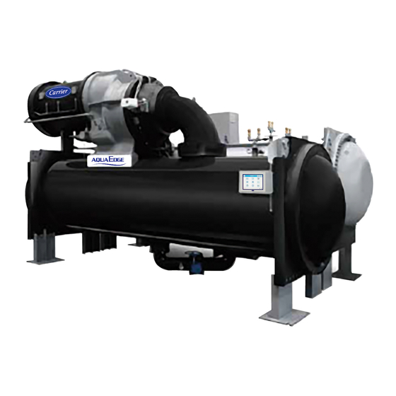
Carrier AquaEdge 19XR series Start-Up, Operation And Maintenance Instructions Manual
Single-stage or two-stage
semi-hermetic centrifugal liquid chillers
with pic ii controls and hfc-134a
50/60 hz
Hide thumbs
Also See for AquaEdge 19XR series:
- Installation instructions manual (80 pages) ,
- Start-up, operation and maintenance instructions manual (128 pages)
Table of Contents
Advertisement
Quick Links
Start-Up, Operation, and Maintenance Instructions
SAFETY CONSIDERATIONS
Centrifugal liquid chillers are designed to provide safe
and reliable service when operated within design specifi-
cations. When operating this equipment, use good judg-
ment and safety precautions to avoid damage to
equipment and property or injury to personnel.
Be sure you understand and follow the procedures and
safety precautions contained in the chiller instructions
as well as those listed in this guide.
DANGER
Failure to follow these procedures will result in severe per-
sonal injury or death.
DO NOT VENT refrigerant relief valves within a building.
Outlet from rupture disc or relief valve must be vented out-
doors in accordance with the latest edition of ANSI/
ASHRAE 15 (American National Standards Institute/
American Society of Heating, Refrigerating, and Air-
Conditioning Engineers). The accumulation of refrigerant
in an enclosed space can displace oxygen and cause
asphyxiation.
PROVIDE adequate ventilation in accordance with ANSI/
ASHRAE 15, especially for enclosed and low overhead
spaces. Inhalation of high concentrations of vapor is harm-
ful and may cause heart irregularities, unconsciousness, or
death. Misuse can be fatal. Vapor is heavier than air and
reduces the amount of oxygen available for breathing.
Product causes eye and skin irritation. Decomposition
products are hazardous.
DO NOT USE OXYGEN to purge lines or to pressurize a
chiller for any purpose. Oxygen gas reacts violently with
oil, grease, and other common substances.
NEVER EXCEED specified test pressures. VERIFY the
allowable test pressure by checking the instruction litera-
ture and the design pressures on the equipment nameplate.
DO NOT USE air for leak testing. Use only refrigerant or
dry nitrogen.
DO NOT VALVE OFF any safety device.
BE SURE that all pressure relief devices are properly
installed and functioning before operating any chiller.
RISK OF INJURY OR DEATH by electrocution. High
voltage is present on motor leads even though the motor is
not running when a solid-state or wye-delta mechanical
starter is used. Open the power supply disconnect before
touching motor leads or terminals.
Manufacturer reserves the right to discontinue, or change at any time, specifications or designs without notice and without incurring obligations.
Catalog No. 04-53190045-01
Printed in U.S.A.
Form 19XR,XRV-CLT-10SS
Single-Stage or Two-Stage
Semi-Hermetic Centrifugal Liquid Chillers
with PIC II Controls and HFC-134a
WARNING
Failure to follow these procedures may result in personal
injury or death.
DO NOT USE TORCH to remove any component. System
contains oil and refrigerant under pressure.
To remove a component, wear protective gloves and gog-
gles and proceed as follows:
a. Shut off electrical power to unit.
b. Recover refrigerant to relieve all pressure from sys-
tem using both high-pressure and low pressure ports.
c. Traces of vapor should be displaced with nitrogen
and the work area should be well ventilated. Refrig-
erant in contact with an open flame produces toxic
gases.
d. Cut component connection tubing with tubing cutter
and remove component from unit. Use a pan to catch
any oil that may come out of the lines and as a gage
for how much oil to add to the system.
e. Carefully unsweat remaining tubing stubs when nec-
essary. Oil can ignite when exposed to torch flame.
DO NOT USE eyebolts or eyebolt holes to rig chiller sec-
tions or the entire assembly.
DO NOT work on high-voltage equipment unless you are a
qualified electrician.
DO NOT WORK ON electrical components, including
control panels, switches, starters, or oil heater until you are
sure ALL POWER IS OFF and no residual voltage can
leak from capacitors or solid-state components.
LOCK OPEN AND TAG electrical circuits during servic-
ing. IF WORK IS INTERRUPTED, confirm that all cir-
cuits are deenergized before resuming work.
AVOID SPILLING liquid refrigerant on skin or getting it
into the eyes. USE SAFETY GOGGLES. Wash any spills
from the skin with soap and water. If liquid refrigerant
enters the eyes, IMMEDIATELY FLUSH EYES with
water and consult a physician.
NEVER APPLY an open flame or live steam to a refriger-
ant cylinder. Dangerous overpressure can result. When it is
necessary to heat refrigerant, use only warm (110 F [43 C])
water.
DO NOT REUSE disposable (nonreturnable) cylinders or
attempt to refill them. It is DANGEROUS AND ILLE-
GAL. When cylinder is emptied, evacuate remaining gas
pressure, loosen the collar, and unscrew and discard the
valve stem. DO NOT INCINERATE.
CHECK THE REFRIGERANT TYPE before adding
refrigerant to the chiller. The introduction of the wrong
refrigerant can cause damage or malfunction to this chiller.
(Warnings continued on next page.)
Pg 1
AquaEdge
19XR,XRV
50/60 Hz
12-16 Replaces: 19XR,XRV-CLT-9SS
®
Advertisement
Table of Contents
Troubleshooting

Subscribe to Our Youtube Channel
Related Manuals for Carrier AquaEdge 19XR series


Summary of Contents for Carrier AquaEdge 19XR series
-
Page 1: Safety Considerations
® AquaEdge 19XR,XRV Single-Stage or Two-Stage Semi-Hermetic Centrifugal Liquid Chillers with PIC II Controls and HFC-134a 50/60 Hz Start-Up, Operation, and Maintenance Instructions SAFETY CONSIDERATIONS WARNING Centrifugal liquid chillers are designed to provide safe and reliable service when operated within design specifi- Failure to follow these procedures may result in personal cations. -
Page 2: Table Of Contents
INTRODUCTION ........5 (latest edition). Contact Carrier for further information on ABBREVIATIONS AND EXPLANATIONS. - Page 3 Interface ... . . 72 ® Carrier Comfort Network Remote Reset of Alarms ......54 Check Starter .
- Page 4 CONTENTS (cont) Page Page • OPTIONAL THERMAL DISPERSION FLOW WEEKLY MAINTENANCE......95 SWITCH CALIBRATION Check the Lubrication System ....95 Check Optional Pumpout System SCHEDULED MAINTENANCE .
-
Page 5: Introduction
— Chiller Control Module tem before performing start-up procedures. Procedures in this ® — Carrier Comfort Network manual are arranged in the sequence required for proper chiller — Counterclockwise — Clockwise start-up and operation. - Page 6 19XR T* 64 – Description 19XR– — High Efficiency Semi-Hermetic Special Order Indicator Centrifugal Liquid Chiller – — Standard S — Special Order 19XRV — High Efficiency Semi-Hermetic Centrifugal Liquid Chiller with Unit-Mounted VFD Motor Voltage Code Code Volts-Phase-Hertz Cooler Size† 60 —...
-
Page 7: Cooler
An optional • displays status of motor starter pumpout system is used to transfer refrigerant from vessel to • provides access to other CCN (Carrier Comfort Net- vessel. ® work... - Page 8 FRONT VIEW LEGEND 1 — Guide Vane Actuator 2 — Suction Elbow 3 — International Chiller Visual Control (ICVC) 4 — Chiller Identification Nameplate 5 — Cooler Auto Reset Relief Valves 6 — Cooler Pressure Transducer 7 — Condenser In/Out Temperature Thermistors 8 —...
- Page 9 FRONT VIEW LEGEND 1 — Guide Vane Actuator 2 — Suction Elbow 3 — Chiller Identification Nameplate 4 — Condenser Auto Reset Relief Valves 5 — Condenser In/Out Temperature Thermistors 6 — Cooler In/Out Temperature Thermistors 7 — Cooler Pressure Transducer 8 —...
-
Page 10: Refrigeration Cycle
chamber vapor from entering the cooler. When liquid refriger- REFRIGERATION CYCLE ant passes through the valve, some of it flashes to vapor in the The compressor continuously draws refrigerant vapor from reduced pressure on the cooler side. In flashing, it removes heat the cooler at a rate set by the amount of guide vane opening. -
Page 11: Motor And Oil Cooling Cycle
ISOLATION VALVE FLASC CHAMBER CONDENSER WATER FLOAT VALVE CHAMBER HOT GAS BYPASS (OPTIONAL) REFRIGERANT MOISTURE/ FILTER COOLING FLOW DRIER DAMPER ISOLATION INDICATOR VALVE VALVE ORIFICE ROTOR HGBP VALVE REFRIGERANT FITTING TRANSMISSION ISOLATION VALVE REFRIGERANT LIQUID MOTOR REFRIGERANT VAPOR ORIFICE FLOAT BALL VALVE FITTING REFRIGERANT LIQUID/VAPOR... -
Page 12: Vfd Cooling Cycle
Flow to the motor cooling system passes through an orifice directed to the gears and the high speed shaft bearings; the re- and into the motor. Once past the orifice, the refrigerant is di- maining flow is directed to the motor shaft bearings. Oil drains rected over the motor by a spray nozzle. - Page 13 REAR MOTOR FWD MOTOR OIL SUPPLY TO BEARING BEARING FORWARD HIGH SPEED BEARING LABYRINTH GAS LINE MOTOR COOLING LINE FILTER FLOW SIGHT GLASS ISOLATION VALVE FILTER TXV BULB PRESSURE ISOLATION PUMP TRANSDUCER VALVES STRAINER HEATER OIL PUMP COOLER EDUCTOR FILTER MOTOR ISOLATION SIGHT...
-
Page 14: Bearings
During the chiller start-up, the oil pump is energized and the rotor includes a babbitted thrust face which opposes the provides 40 seconds of lubrication to the bearings after pres- normal axial forces which tend to pull the assembly towards sure is verified before starting the compressor. -
Page 15: Secondary Oil Recovery Method
All starters and freestanding VFDs must include a Carrier collected by the primary oil recovery method. control module called the Integrated Starter Module (ISM), ex- cluding the Benshaw solid-state and wye-delta MX3™... -
Page 16: Unit-Mounted Wye-Delta Starter
Starter control, monitoring, and motor breaker so that power is supplied to them if the disconnect is protection is provided by Carrier’s Integrated Starter Module open. Refer to wiring schematic in Physical data section. (ISM) except for Benshaw MX3™ wye-delta starters which do... -
Page 17: Controls
The chiller control PIC II System Components — in Carrier specifications such that operation with PIC II con- system is called the PIC II (Product Integrated Control II). See trols remains consistent. -
Page 18: International Chiller Visual
MOTOR TEMPERATURE SENSOR CABLE COMPRESSOR OIL DISCHARGE OIL RECLAIM PRESSURE CABLE SIGHT GLASS BEARING TEMPERATURE SENSOR CABLE COMPRESSOR OIL SUMP DIFFUSER PRESSURE PRESSURE CABLE AND DIFFUSER ACTUATOR CABLE (FRAME 4 & 5 COMPRESSOR ONLY) COMPRESSOR OIL SUMP TEMPERATURE CABLE CABLE FROM GUIDE VALVE CONTROL PANEL ACTUATOR CABLE... -
Page 19: Hot Gas Bypass Contactor Relay (3C)
monitors starter inputs such as line voltage, motor current, CONTROL TRANSFORMERS (T1, T2) — These trans- ground fault, remote start contact, spare safety, condenser high formers convert incoming control voltage to 24 vac power for pressure, oil pump interlock, starter 1M, and run contacts. It the 3 power panel contactor relays, CCM, and ICVC. - Page 20 CARRIER COMFORT CONTROL POWER CIRCUIT BREAKERS NETWORK (CCN) (CB1,CB2) INTERFACE CONTROL PANEL DISPLAY (FRONT VIEW) CHILLER VISUAL CONTROLLER (ICVC) FRONT VIEW SURGE/HGBP PARAMETER CHILLER CONTROL LABEL MODULE (CCM) a19-1956 CONTROL PANEL INTERNAL VIEW a19-1855 DIFFUSER SCHEDULE SETTINGS (FRAME 5 COMPRESSOR...
-
Page 21: Sensors
Table 2 — Standard Instrumentation Sensors TYPE LOCATION MONITORED REMARKS Entering Chilled Water Cooler Inlet Nozzle Leaving Chilled Water Cooler Outlet Nozzle Entering Condenser Water Condenser Inlet Nozzle Leaving Condenser Water Condenser Outlet Nozzle TEMPERATURE Evaporator Saturation Sensor Well on Bottom of Evaporator Compressor Discharge Compressor Volute Oil Sump... -
Page 22: Alarms And Alerts
times. The PIC II can be placed in the local operating When an alarm is detected, the ICVC default screen will mode by pressing the CCN softkey. When RUN STATUS freeze (stop updating) at the time of alarm. The freeze enables is READY, the chiller will attempt to start up. -
Page 23: To View Status
• Press to scroll the cursor bar up in order to PREVIOUS highlight a point or to view points above the current POINT STATUS screen. 19XR_II MAINSTAT Control Mode Run Status Ready Start Inhibit Timer 0.0 Min Occupied? System Alert/Alarm NORMAL Chiller Start/Stop STOP... - Page 24 DEFAULT SCREEN LOCAL RESET MENU (SOFTKEYS) Start Chiller In CCN Control Start Chiller in Local Control Clear Alarms Access Main Menu SCHEDULE SETPOINT STAT US SERVICE List the (ENTER A 4-DIGIT P ASSWORD) (V ALUES SHOWN AT F ACTORY DEFAULT) 1 1 1 Status T ables List the Service Ta bles...
- Page 25 SERVICE TABLE PREVIOUS SELECT EXIT NEXT ALERT HISTORY ALARM HISTORY Alert History Display Alarm History (The table holds up to 25 alerts (The table holds up to 25 alarms with the most recent alert at with the most recent alarm at the top of the screen.) See Note.
- Page 26 — English (U.S. IMP.) or S.I. Metric Units — Password — LID Language LEGEND CCN — Carrier Comfort Network ICVC — International Chiller Visual Controller — Integrated Starter Module a19-1859 PIC II — Product Integrated Control II...
-
Page 27: Time Schedule Operation
To Remove a Force 1. On the point status table press NEXT PREVIOUS to highlight the desired value. 2. Press to access the highlighted value. SELECT 3. Press to remove the override and return the RELEASE Fig. 22 — Example of Time Schedule point to the PIC II’s automatic control. -
Page 28: To View And Change Set Points
TO VIEW AND CHANGE SET POINTS (Fig. 23) Operation section, page 63. The ice build (ICE BUILD) function is also activated and configured from the SER- 1. To view the SETPOINT table, from the MENU screen VICE menu. press SETPOINT 3. -
Page 29: Alarms And Alerts
If this happens, you LEGEND must re-enter your password to access the tables shown in — Carrier Comfort Network Examples 10 through 25. — Chilled Water 4. Terms in the Description column of these tables are listed as —... - Page 30 Table 3 — ICVC Display Data (cont) EXAMPLE 2 — MAINSTAT DISPLAY SCREEN To access this display from the ICVC default screen: 1. Press MENU 2. Press STATUS MAINSTAT will be highlighted). 3. Press SELECT DESCRIPTION STATUS UNITS POINT Control Mode NOTE 2 NOTE 2 MODE...
- Page 31 Table 3 — ICVC Display Data (cont) EXAMPLE 3 — STARTUP DISPLAY SCREEN To access this display from the ICVC default screen: 1. Press MENU 2. Press STATUS 3. Scroll down to highlight STARTUP 4. Press SELECT DESCRIPTION STATUS UNITS POINT Actual Guide Vane Pos 0-100...
- Page 32 Table 3 — ICVC Display Data (cont) EXAMPLE 5 — HEAT_EX DISPLAY SCREEN To access this display from the ICVC default screen: 1. Press MENU 2. Press STATUS 3. Scroll down to highlight HEAT_EX 4. Press SELECT DESCRIPTION STATUS UNITS POINT **Chilled Water Delta P -6.7-420...
- Page 33 Table 3 — ICVC Display Data (cont) EXAMPLE 7 — ISM_STAT DISPLAY SCREEN To access this display from the ICVC default screen: 1. Press MENU 2. Press STATUS 3. Scroll down to highlight ISM_STAT 4. Press SELECT DESCRIPTION STATUS UNITS POINT ISM Fault Status 0-255...
- Page 34 Table 3 — ICVC Display Data (cont) EXAMPLE 9 — SETPOINT DISPLAY SCREEN To access this display from the ICVC default screen: 1. Press MENU 2. Press SETPOINT 3. Press SELECT DESCRIPTION STATUS UNITS POINT DEFAULT Base Demand Limit 40-100 Control Point LCW Setpoint 10-120...
- Page 35 Table 3 — ICVC Display Data (cont) EXAMPLE 12 — LL_MAINT DISPLAY SCREEN To access this display from the ICVC default screen: 1. Press MENU 2. Press SERVICE 3. Scroll down to highlight CONTROL ALGORITHM STATUS 4. Press SELECT 5. Scroll down to highlight LL_MAINT.
- Page 36 Table 3 — ICVC Display Data (cont) EXAMPLE 13 — SURGPREV DISPLAY SCREEN To access this display from the ICVC default screen: 1. Press MENU 2. Press SERVICE 3. Scroll down to highlight CONTROL ALGORITHM STATUS 4. Press SELECT 5. Scroll down to highlight SURGPREV 6.
- Page 37 Table 3 — ICVC Display Data (cont) EXAMPLE 15 — WSMCHRLE DISPLAY SCREEN To access this display from the ICVC default screen: 1. Press MENU 2. Press SERVICE 3. Scroll down to highlight CONTROL ALGORITHM STATUS 4. Press SELECT 5. Scroll down to highlight WSMCHRLE 6.
- Page 38 Table 3 — ICVC Display Data (cont) EXAMPLE 17 — ISM_CONF DISPLAY SCREEN To access this display from the ICVC default screen: 1. Press MENU 2. Press SERVICE 3. Scroll down to highlight ISM (STARTER) CONFIG DATA 4. Press SELECT 5.
- Page 39 Table 3 — ICVC Display Data (cont) EXAMPLE 18 — OPTIONS DISPLAY SCREEN To access this display from the ICVC default screen: 1. Press MENU 2. Press SERVICE 3. Scroll down to highlight EQUIPMENT SERVICE 4. Press SELECT 5. Scroll down to highlight OPTIONS 6.
- Page 40 Table 3 — ICVC Display Data (cont) EXAMPLE 20 — SETUP1 DISPLAY SCREEN To access this display from the ICVC default screen: 1. Press MENU 2. Press SERVICE 3. Scroll down to highlight EQUIPMENT SERVICE 4. Press SELECT 5. Scroll down to highlight SETUP1 6.
- Page 41 Table 3 — ICVC Display Data (cont) EXAMPLE 21 — SETUP2 DISPLAY SCREEN To access this display from the ICVC default screen: 1. Press MENU 2. Press SERVICE 3. Scroll down to highlight EQUIPMENT SERVICE 4. Press SELECT 5. Scroll down to highlight SETUP2 6.
- Page 42 Table 3 — ICVC Display Data (cont) EXAMPLE 23 — RAMP_DEM DISPLAY SCREEN To access this display from the ICVC default screen: 1. Press MENU 2. Press SERVICE 3. Scroll down to highlight EQUIPMENT SERVICE 4. Press SELECT 5. Scroll down to highlight RAMP_DEM 6.
-
Page 43: Pic Ii System Functions
• The SETPOINT menu allows set point adjustments, such Refer to ICVC Opera- PIC II System Functions — as the entering chilled water and leaving chilled water tion and Menus section on page 21. setpoints. NOTE: Words not part of paragraph headings and printed in all •... -
Page 44: Capacity Control
A No Flow determination is made on the evaporator side if PROPORTIONAL DEC (Decrease) BAND, and PROPOR- (1) the EVAP SATURATION TEMP reads lower than 1° F TIONAL ECW (Entering Chilled Water), GAIN in the SER- (0.6° C) below the EVAP REFRIG TRIPPOINT, or (2) EVAP VICE/EQUIPMENT SERVICE/SETUP2 screen. -
Page 45: Ecw Control Option
Constant Flow Surge Prevention and VFD INCREASE STEP can be viewed and modified in the SETUP2 display screen. TARGET and ACTUAL VFD SPEED Normal Capacity Control Mode occurs when ACTIVE can be viewed in the COMPRESS screen. DELTA T> SURGE LINE DELTA T. Surge Prevention Mode Level 1 occurs when ACTIVE ECW CONTROL OPTION —... -
Page 46: Diffuser Control
Optimization (VDO) algorithm. Configurations for VDO are The ECW GAIN affects the size of the LCW CONTROL produced by the Carrier's chiller selection program and are en- POINT change in proportion to the difference between the tered into the VDO_SRD screen. The starting point diffuser ECW SETPOINT and ECW TEMPERATURE. -
Page 47: Demand Limiting
up (on) position despite the notation on the CCM board. See 2 mA Fig. 26. (0%) 100% 4 mA A DEMAND KILOWATTS monitoring feature is also avail- Open (0.2%) surge more likely able. This feature provides a display of average demand (power) in kilowatts (in the POWER screen). -
Page 48: Safety Controls
VFD, and interface terminals are provided at CONFIGURATION table. See Table 3, Example 16. SCHED- ISM terminal strip J9 (refer to the Carrier Installation Instruc- ULE NUMBER can be changed to any value from 03 to 99. If tions and certified drawings). - Page 49 Table 6 — Protective Safety Limits and Control Settings MONITORED PARAMETER STATE LIMIT COMMENTS 260-270, TEMPERATURE SENSORS OUT Temperature <-40 deg F or >245 deg F for 272,140, Preset Alarm OF RANGE 3 seconds PRESSURE TRANSDUCERS OUT .06>Voltage Ratio>.98 for 3 seconds, Valid Range Preset Alarm, Voltage Ratio=Input Voltage/ 260-270 OF RANGE...
- Page 50 Table 6 — Protective Safety Limits and Control Settings (cont) MONITORED PARAMETER STATE LIMIT COMMENTS OIL PRESSURE DELTA P < 18 PSID and startup LOW PRESSURE Preset Alert complete OIL - PRESSURE SENSOR OIL PRESSURE DELTA P > 4 PSI immediately Preset Alarm FAULT before oil pump turned on...
-
Page 51: Default Screen Freeze
Table 6 — Protective Safety Limits and Control Settings (cont) MONITORED PARAMETER STATE LIMIT COMMENTS Any LOAD CURRENT PHASE > 108% for Exces- Preset Alarm, Force ACTIVE DEMAND OVERLOAD TRIP sive Time Period LIMIT in MAINSTAT screen LOCKED ROTOR TRIP Motor Locked Rotor Amps exceeded Preset Alarm EXCESSIVE AMPS... -
Page 52: Ramp Loading
BRG TEMP calculation. The default value is 1.4 and will nor- “Start Speed” which is the lower of VFD MAXIMUM SPEED mally be left at that value unless other wise advised by Carrier or the configured value of VFD START SPEED. VFD START Service Engineering. - Page 53 Table 7 — Capacity Overrides SECOND STAGE SET POINT FIRST STAGE SET POINT OVERRIDE OVERRIDE (FORCED CAPACITY (CAPACITY INHIBIT) TERMINATION CONDITION DECREASE) (CONFIGURABL VIEW/MODIFY E OVERRIDE OVERRIDE CONFIGURABLE ON ICVC VALUE VALUE PARAMTER) DEFAULT VALUE RANGE SCREEN HIGH CONDENSER PRESSURE > CONDENSER PRES- CONDENSER CONDENSER...
-
Page 54: Oil Cooler
OPTION (ICVC_PSWD menu) is set to ENABLE. A variety ® ensures that, if the automatic system is malfunctioning, the of Carrier Comfort Network software systems including chiller will not repeatedly cycle on and off. ComfortVIEW™ or Network Service Tool™ can access the PIC II controls and reset the displayed alarm. -
Page 55: Condenser Freeze Prevention
WATER temperature is greater than the TOWER FAN HIGH This control algo- Condenser Freeze Prevention — SETPOINT (SETPOINT menu, default 75 F [23.9 C]). rithm helps prevent condenser tube freeze-up by energizing the condenser pump relay. The PIC II controls the pump and, by The TOWER FAN RELAY HIGH is turned off when the starting it, helps to prevent the water in the condenser from CONDENSER WATER PUMP is off or the EVAPORATOR... -
Page 56: Fast Power Source Transfers
difference between the entering and leaving chilled water When the electri- Fast Power Source Transfers — temperature. cal system is being prepared to transfer power from generator power back to utility power or vice-versa, and the power trans- To configure Reset Type 3, enter the chilled water tempera- fer is an open transition type, and time to transfer is less than 5 ture difference (the difference between entering and leaving seconds, the chiller should be stopped before the transfer oc-... -
Page 57: Surge Protection (Fixed Speed Chiller)
configured threshold. The threshold is calculated from a com- Surge Protection (Fixed Speed Chiller) — bination of GUIDE VANE POSITION and the difference be- PIC II monitors surge, which results in a fluctuation on the tween CONDENSER PRESSURE and EVAPORATOR compressor motor amperage. -
Page 58: Surge Protection (Vfd Chiller)
Excessive Compressor Surge / Low Speed Alarm tem device(s) to produce the desired effect. Carrier does not (236). Both SURGE COUNTS and SURGE PROTECTION make any claim that this output is... -
Page 59: Lead/Lag Control
CHILLER COMMUNICATION WIRING — Refer to the EQUIPMENT SERVICE table. See Table 3, Example 22. ® chiller’s Installation Instructions, Carrier Comfort Network Lead/lag status during chiller operation can be viewed on the Interface section for information on chiller communication LL_MAINT display screen, which is accessed from the SER- wiring. - Page 60 The lead chiller responds to normal start/stop controls such minute for a cumulative duration greater than the PULL- as the occupancy schedule, a forced start or stop, and remote DOWN TIMER setting in the LEAD/LAG screen. start contact inputs. After completing start-up and ramp load- When all the above requirements have been met, the lag ing, the PIC II evaluates the need for additional capacity.
-
Page 61: Faulted Chiller Operation
capacity, which is defined as 115 – LAG % CAPACITY. addition, the CONTROL POINT for the lag chiller will be mod- The LAG % CAPACITY parameter is on the LEADLAG ified to a value of 3 F (1.67 C) less than the lead chiller’s screen, which is accessed from the EQUIPMENT SER- CONTROL POINT value. -
Page 62: Ice Build Initiation
ICE BUILD INITIATION — The ice build time schedule • 20 DEMAND LIMIT (configured (OCCPC02S) is the means for activating the ice build option. RAMP_DEM screen). The ice build option is enabled if: TERMINATION OF ICE BUILD — The ice build function •... -
Page 63: Attaching To Other Ccn Modules
1. From the main MENU screen, press the SERVICE softkey. The softkeys now correspond to the numerals 1, 2, 3, 4. 2. Press the four digits of the password, one at a time. An asterisk (*) appears as each digit is entered NOTE: The initial factory-set password is 1-1-1-1. -
Page 64: Holiday Scheduling
holidays as configured in the local chiller’s control will be ap- plied. If a network is present and one time broadcaster on the network has been enabled, current time and date, DST, and hol- iday schedules as configured in the controls of the designated time broadcaster will be applied to all CCN devices (including chillers) on the network. - Page 65 are represented in the START INHIBIT TIMER and can be If the water/brine temperature is high enough, the start-up viewed on the MAINSTAT screen and DEFAULT screen. The sequence continues and checks the guide vane position. If the timer must expire before the chiller will start. If the timers have guide vanes are more than 4% open, the start-up waits until the not expired the RUN STATUS parameter on the MAINSTAT PIC II closes the vanes.
-
Page 66: Shutdown Sequence
Table 9 — Prestart Checks QUANTITY CHECKED REQUIREMENT ALERT STATE IF FALSE < 8 (not counting recycle restarts or auto restarts after power failure) STARTS IN 12 HOURS ALERT is cleared once RESET is pressed. COMP THRUST BRG TEMP < [COMP THRUST BRG ALERT] –10° F (5.6° C) COMP MOTOR WINDING TEMP <... -
Page 67: Safety Shutdown
System — condition and the water circuits are full. Storage Tanks section, page 90 for pumpout system prepara- Carrier recommends the use of an Refrigerant Tracer — tion, refrigerant transfer, and chiller evacuation. environmentally acceptable refrigerant tracer for leak testing Remove any pack- Remove Shipping Packaging —... -
Page 68: Leak Test Chiller
Plainly mark any leaks that are found. contaminants from the refrigerant, Carrier recommends the d. Release the pressure in the system. following leak test procedure. Refer to Tables 11A and 11B for e. - Page 69 a19-1625...
- Page 70 Table 11A — HFC-134a Pressure — Table 11B — HFC-134a Pressure — Temperature (F) Temperature (C) TEMPERATURE, PRESSURE TEMPERATURE, PRESSURE (PSIG) (KPA) 6.50 –18.0 44.8 7.52 –16.7 51.9 8.60 –15.6 59.3 9.66 –14.4 66.6 10.79 –13.3 74.4 11.96 –12.2 82.5 13.17 –11.1 90.8...
-
Page 71: Standing Vacuum Test
6. If no leak is found after a retest: Dehydration can be done at room temperatures. Using a cold trap (Fig. 34) may substantially reduce the time required a. Transfer the refrigerant to the pumpout storage to complete the dehydration. The higher the room temperature, tank and perform a standing vacuum test as out- the faster dehydration takes place. -
Page 72: Check Optional Pumpout Compressor
Carrier assumes no responsibility for chiller damage result- CAUTION ing from untreated or improperly treated water. If the motor starter is a solid-state starter, the motor leads... -
Page 73: Check Starter
(Fig. 2 and 3). If oil is added, it must meet ance from moving parts, and correct connection. Carrier’s specification for centrifugal compressor use as de- scribed in the Oil Specification section. Charge the oil through 2. -
Page 74: Software Configuration
VICE menu will not be possible unless the ICVC_PSWD quirements. If no schedule is available, the default is factory set menu on the STATUS screen is accessed by a Carrier for 24 hours occupied, 7 days per week including holidays. -
Page 75: Vfd Field Setup And Verification
automatically after power-up. Current and Ramp Time config- VFD Field Setup and Verification urations are entered in the CFN menu. CT Ratio configuration is entered in the FUN menu. See Table 13 for menu structure IMPORTANT: The VFD controller has been factory config- and Table 14 for settings. -
Page 76: Label Locations
Table 13 — Benshaw RediStart MX3 Menu Structure ISM MENU CFN MENU FUN MENU FL MENU E MENU Shows parameters entered on Initial Current as % RLA Meter #1 display Fault Log (9 faults) Event Log (99 events) the ISM_CONF screen on the Max. -
Page 77: Drive Protection And Other Incoming Wiring
SAFETY CODE FOR MECHANICAL REFRIGERATION. THE COMPRESSOR MOTOR CONTROLLER VFD Cooling System Leak Inspection AND OVERLOAD PROTECTION MUST BE IN ACCORDANCE WITH CARRIER SPECIFICATION Z-415. 1. Check for leaks on the refrigerant cooling flange connec- tions to the VFD enclosure. a19-1881 2. -
Page 78: Vfd Control Verification (Non-Running)
5. Scroll down and select the ISM_CONF DATA screen to 2. Press STATUS modify or view the ISM parameters: 3. Press COMPRESS 4. Press SELECT DESCRIPTION SETTING 5. Set TARGET VFD SPEED to 0%. STARTER TYPE (3 = VFD) Verify that the VFD SPEED REFERENCE shown on the MOTOR RATED VOLTAGE from "Load Side"... -
Page 79: Hand Calculate Surge Prevention
3. Calculate an average Amp Meter Current of the three in- HAND CALCULATE SURGE PREVENTION CONFIG- put phases. URATIONS — The configurations entered determine Surge Prevention line that the controls use to raise the speed of 4. Calculate the line side error ratio using the following the VFD if the compressor operating point nears this line. -
Page 80: Configurations
• Surge/HGBP Deadband controls the amount the ACTIVE DELTA TSAT must drop below the Surge Prevention to de-activate Surge Prevention. Fine Tuning VPF Surge Prevention — Figures 37-40 show how the parameters defined below will affect the configured Tsmin=30 surge line. NOTE: Before tuning surge prevention check for VFD speed limitation or capacity overrides. -
Page 81: Configure Diffuser Control If
MODIFY EQUIPMENT CONFIGURATION IF NECES- SARY — The EQUIPMENT SERVICE table has screens to Fig. 40 — Effect of SURGE LINE SPEED FACTOR select, view, or modify parameters. Carrier’s certified drawings on Surge Prevention have the configuration values required for the jobsite. Modify these values only if requested. -
Page 82: Perform A Control Test
• fourth bit = 1 indicates that the alarm should be read and Table 15 — Control Test Menu Functions processed by an alarm printer interface (an optional mod- ule) or ServiceLink™ modules. TESTS TO BE DEVICES TESTED PERFORMED The RE-ALARM time is a time period after which, if a preex- 1. -
Page 83: Guide Vane Actuator Calibration
GUIDE VANE ACTUATOR CALIBRATION — This au- If the transducer value is not within the calibration range, tomated procedure is performed at the factory prior to new the transducer will return to the original reading. If the chiller shipment. During this test, the CCM outputs a discrete pressure is within the allowed range (noted above), check 24-v signal from terminal J11 to fully open and fully close the the voltage ratio of the transducer. -
Page 84: High Altitude Locations
Increase the sensitivity of the flow switch by turning the ad- 3. Slowly open the refrigerant cooling isolation valve. The justment potentiometer clockwise until the yellow LED is lit. chiller cooler and condenser pressures will gradually equalize. This process takes approximately 15 minutes. In case of nuisance trips at low flow increase the sensitivity of the switch by turning the potentiometer clockwise. - Page 85 RELIEF PUMPOUT VALVE COMPRESSOR SEPARATOR CONDENSER PUMPOUT CONDENSER CHECK COOLER VALVE STORAGE VESSEL a19-2434 NOTE: Maintain at least 2 ft (610 mm) clearance around storage tank for service and operation work. Fig. 43 — Typical Optional Pumpout System Piping Schematic with Storage Tank RELIEF PUMPOUT VALVE...
-
Page 86: Initial Start-Up
temperature difference to design conditions or minimum 5. The PIC II eventually shows an alarm for motors amps differential. not sensed. Reset this alarm and continue with the initial start-up. The 19XR chiller refrigerant charges for each cooler and condenser code are listed in the Heat Exchanger Data tables in 6. -
Page 87: Initial Start-Up
REVIEW THE START-UP OPERATION, AND MAINTE- A chiller STOP To Prevent Accidental Start-Up — override setting may be entered to prevent accidental start-up NANCE MANUAL. during service or whenever necessary. Access the MAINSTAT screen and using the softkeys, high- NEXT PREVIOUS OPERATING INSTRUCTIONS light the CHILLER START/STOP parameter. -
Page 88: To Stop The Chiller
Data Collection module and a Building Supervisor. supplied; see Pumpout and Refrigerant Transfer Procedures) to Contact a Carrier representative for more information. reduce chiller pressure and the possibility of leaks. Maintain a holding charge of 5 to 10 lb (2.27 to 4.5 kg) of refrigerant or ni- PUMPOUT AND REFRIGERANT trogen to prevent air from leaking into the chiller. -
Page 90: To Read Refrigerant Pressures
POSITIVE PRESSURE CHILLERS WITH STORAGE TANKS — In the Valve/Condition tables that accompany these instructions, the letter “C” indicates a closed valve. Figures 43 DANGER and 44 show the locations of the valves. During transfer of refrigerant into and out of the optional storage tank, carefully monitor the storage tank level gage. -
Page 91: Chillers With Isolation Valves
Transfer Refrigerant from Storage Tank Vessel to Chiller h. Close valves 1A, 1B, 2, 5, 6. VALVE 1A 1B 10 11 WARNING CONDITION During transfer of refrigerant into and out of the i. Turn off pumpout condenser water. 19XR,XRV storage tank, carefully monitor the storage Transfer Refrigerant from Chiller to Storage Tank Vessel tank level gage. - Page 92 isolation for certain service conditions when the isolation valve o. Close remaining valves. package is specified. VALVE Transfer Refrigerant from Cooler to Condenser CONDITION a. Turn off chiller water pumps and pumpout con- p. Remove charging hose between 7 and 8 (evacuate denser water supply (if applicable).
-
Page 93: Procedures
o. Close remaining valves. d. Gradually crack open valve 5 to increase chiller pressure to 35 psig (241 kPa). Slowly feed refriger- ant to prevent freeze-up. VALVE CONDITION e. Open valve 5 fully after the chiller pressure rises above the freezing point of the refrigerant. Let the p. -
Page 94: Leak Rate
4. Observe the pressure gage on the chiller and close the regulating valve when the pressure reaches test level. Do In addition, Carrier recommends that leaks totalling less not exceed 140 psig (965 kPa). than the above rate but more than a rate of 0.1% of the total charge per year should be repaired during annual maintenance 5. -
Page 95: Trim Refrigerant Charge
• Frame E compressor — 18 gal (67.8 L) 4. Close the isolation valves located on both ends of the oil The added oil must meet Carrier specifications for the filter. Have rags and a catch basin available to collect oil 19XR. -
Page 96: Oil Specification
Ensure that all openings are free of obstructions. The polyolester-based oil (P/N: PP23BZ103) may be ordered from your local Carrier representative. 4. Examine the cover gasket and replace if necessary. See Fig. 50 for a view of the float valve design. Inspect the Carrier recommends that a yearly oil Oil Changes —... -
Page 97: Maintenance
TO COOLER During the tube cleaning process, use brushes specially de- signed to avoid scraping and scratching the tube wall. Contact your Carrier representative to obtain these brushes. Do not use O-RING wire brushes. Hard scale may require chemical treatment for its preven- tion or removal. -
Page 98: Inspect The Starting Equipment
Carrier Part Number... . PP23BZ103 or PP23BZ104 The total oil charge is 13 oz. (0.5 L) -
Page 99: Troubleshooting Guide
These messages contain the alarm message with a specified TROUBLESHOOTING GUIDE code. This code or state appears with each alarm and alert mes- The PIC II has many features to help the op- Overview — sage. The ALARM and ALERT HISTORY tables on the ICVC erator and technician troubleshoot a 19XR chiller. -
Page 100: Troubleshooting Guide
Table 16 — ICVC Primary and Secondary Messages and Custom Alarm/Alert Messages with Troubleshooting Guides A. MANUAL STOP PRIMARY MESSAGE SECONDARY MESSAGE PROBABLE CAUSE/REMEDY MANUALLY STOPPED — PRESS CCN OR LOCAL TO START PIC II in OFF mode, press CCN or LOCAL softkey to start unit. TO SELECT CCN OR LOCAL Enter the CONTROL TEST table and select TERMINATE LOCKOUT TERMINATE PUMPDOWN MODE... - Page 101 Table 16 — ICVC Primary and Secondary Messages and Custom Alarm/Alert Messages with Troubleshooting Guides (cont) D. PRE-START ALERTS: These alerts only delay start-up. When alert is corrected, the start-up will continue. No reset is necessary. FAULT PRIMARY SECONDARY PRIMARY CAUSE ADDITIONAL CAUSE/REMEDY STATE MESSAGE...
- Page 102 Table 16 — ICVC Primary and Secondary Messages and Custom Alarm/Alert Messages with Troubleshooting Guides (cont) E. START-UP IN PROGRESS PRIMARY MESSAGE SECONDARY MESSAGE CAUSE/REMEDY STARTUP IN PROGRESS OCCUPIED MODE Chiller is starting. Time schedule is Occupied (OCCUPIED? = YES) REMOTE CONTACT CLOSED Chiller is starting.
- Page 103 Table 16 — ICVC Primary and Secondary Messages and Custom Alarm/Alert Messages with Troubleshooting Guides (cont) G. NORMAL RUN WITH OVERRIDES ICVC ADDITIONAL FAULT PRIMARY MESSAGE SECONDARY MESSAGE PRIMARY CAUSE CAUSE/REMEDY STATE HIGH CONDENSER 120->Condenser Pressure Check condenser water pump operation. PRESSURE [VALUE] exceeded limit of Check for high condenser water temperatures...
-
Page 104: Voltage Drop
Table 16 — ICVC Primary and Secondary Messages and Custom Alarm/Alert Messages with Troubleshooting Guides (cont) H. OUT-OF-RANGE SENSOR ALARMS ADDITIONAL STATE PRIMARY MESSAGE SECONDARY MESSAGE PRIMARY CAUSE CAUSE/REMEDY LEAVING CHILLED WATER 260->Sensor Fault: Check Leaving Check sensor resistance or voltage drop Chilled Water Sensor against Table 17A or 17B. -
Page 105: Voltage Drop
Table 16 — ICVC Primary and Secondary Messages and Custom Alarm/Alert Messages with Troubleshooting Guides (cont) I. CHILLER PROTECTIVE LIMIT FAULTS ICVC ADDITIONAL FAULT PRIMARY MESSAGE SECONDARY MESSAGE PRIMARY CAUSE CAUSE/REMEDY STATE OIL PRESS SENSOR FAULT 227->Oil Pump Delta P [VALUE] OIL PUMP DELTA P >... - Page 106 CCM. Check for 24V across CCM J1-1 and J1-2. Call Carrier Service. *[LIMIT] is shown on the ICVC as the temperature, pressure, voltage, etc., set point predefined or selected by the operator as an override, alert, or alarm condition.
- Page 107 Table 16 — ICVC Primary and Secondary Messages and Custom Alarm/Alert Messages with Troubleshooting Guides (cont) I. CHILLER PROTECTIVE LIMIT FAULTS (cont) ICVC ADDITIONAL FAULT PRIMARY MESSAGE SECONDARY MESSAGE PRIMARY CAUSE CAUSE/REMEDY STATE LOW DISCHARGE SUPERHEAT 240->Check for Oil in Refrigerant or Check ACTUAL SUPERHEAT and SUPERHEAT Overcharge of Refrigerant.
-
Page 108: Voltage Drop
Table 16 — ICVC Primary and Secondary Messages and Custom Alarm/Alert Messages with Troubleshooting Guides (cont) I. CHILLER PROTECTIVE LIMIT FAULTS (cont) ICVC ADDITIONAL FAULT PRIMARY MESSAGE SECONDARY MESSAGE PRIMARY CAUSE CAUSE/REMEDY STATE SPARE TEMPERATURE #1 248->Spare Temperature #1 [VALUE] Check component that SPARE TEMPERATURE exceeded limit of [LIMIT]*. -
Page 109: Voltage Drop
Table 16 — ICVC Primary and Secondary Messages and Custom Alarm/Alert Messages with Troubleshooting Guides (cont) J. CHILLER ALERTS (cont) STATE PRIMARY SECONDARY PRIMARY CAUSE ADDITIONAL MESSAGE MESSAGE CAUSE/REMEDY LINE PHASE 143->Line Current Loss; Check Any LINE VOLTAGE < 50% MOTOR RATED LINE VOLTAGE or there is LOSS ISM Fault History to Identify Phase an excessive difference between the smallest LINE CURRENT and the... -
Page 110: Voltage Drop
Table 16 — ICVC Primary and Secondary Messages and Custom Alarm/Alert Messages with Troubleshooting Guides (cont) J. CHILLER ALERTS (cont) STATE PRIMARY SECONDARY PRIMARY CAUSE ADDITIONAL MESSAGE MESSAGE CAUSE/REMEDY COND PRESS/ 154->Condenser freeze up pre- The chiller is not in Pumpdown Mode and the CONDENSER REFRIG TEMP TOO LOW vention TEMP is less than the CONDENSER FREEZE POINT. - Page 111 Table 16 — ICVC Primary and Secondary Messages and Custom Alarm/Alert Messages with Troubleshooting Guides (cont) K. ISM ALARMS ICVC ADDITIONAL FAULT PRIMARY MESSAGE SECONDARY MESSAGE PRIMARY CAUSE CAUSE/REMEDY STATE 1M CONTACT FAULT 200->1M Aux Contact Fault; Check 1M 1M aux contact is open when it should be closed Contactor and Aux during start or run mode.
-
Page 112: Voltage Drop
Table 16 — ICVC Primary and Secondary Messages and Custom Alarm/Alert Messages with Troubleshooting Guides (cont) K. ISM ALARMS (cont) ICVC ADDITIONAL FAULT PRIMARY MESSAGE SECONDARY MESSAGE PRIMARY CAUSE CAUSE/REMEDY STATE LINE PHASE LOSS 209->Line Phase Loss; Check ISM Fault Any LINE VOLTAGE <... - Page 113 Check motor power leads for phase to phase or phase to ground shorts. Disconnect motor from starter and megger motor windings to ground and phase to phase. Call Carrier Service. PHASE REVERSAL TRIP 221-> Phase Reversal Trip; Check The ISM has detected that the input power is Power Supply phased BAC instead of ABC.
-
Page 114: Voltage Drop
Table 17A — Thermistor Temperature (F) vs. Resistance/Voltage Drop PIC II PIC II PIC II TEMPERATURE RESISTANCE TEMPERATURE RESISTANCE TEMPERATURE RESISTANCE VOLTAGE VOLTAGE VOLTAGE (OHMS) (OHMS) (OHMS) DROP (V) DROP (V) DROP (V) –25 4.700 97,706 2.565 6,568 0.630 –24 4.690 94,549 2.533... -
Page 115: Voltage Drop
Table 17B — Thermistor Temperature (C) vs. Resistance/Voltage Drop PIC II PIC III TEMPERATURE RESISTANCE TEMPERATURE RESISTANCE VOLTAGE VOLTAGE (OHMS) (OHMS) DROP (V) DROP (V) –33 4.722 105 616 1.338 2 272 –32 4.706 99 640 1.300 2 184 –31 4.688 93 928 1.263... -
Page 116: Checking Pressure Transducers
CHECK SENSOR ACCURACY — Place the sensor in a calibration points are 0 psig (0 kPa) and between 25 and 250 medium of known temperature and compare that temperature psig (173 and 1724 kPa). To calibrate these transducers: to the measured reading. The thermometer used to determine 1. -
Page 117: Control Algorithms Checkout Procedure
Proper operation of all modules is indicated by LEDs (light- Control Algorithms Checkout Procedure — emitting diodes) located on the circuit board of the ICVC and of the tables on the ICVC SERVICE menu is CONTROL CCM. ALGORITHM STATUS. The maintenance screens may be viewed from the CONTROL ALGORITHM STATUS table to There is one green and one red LED located on the CCM see how a particular control algorithm is operating. - Page 118 MODULE PART NUMBER CCN INTERFACE SOFTWARE PART NUMBER CONNECTION ICVC BACK OF CVC J7 SIO J1 POWER/ J8 SERVICE a19-1868 Fig. 54 — Rear of ICVC (International Chiller Visual Controller)
-
Page 119: Inputs
SW1 (S10 ADDRESS DISCRETE DISCRETE DIP SWITCH) 24 VAC OUTPUTS OUTPUTS SET ALL TO OFF ANALOG OUT SW2 (V/I CONFIGURATION DIP SWITCH) V/I INPUTS STAT COMM THERMISTORS DIFF PRESSURE PRESSURE a19-1869 Fig. 55 — Chiller Control Module (CCM) INTEGRATED STARTER MODULE CONTACT INPUTS GROUND 115 VAC... -
Page 120: Replacing Defective Processor Modules
Benshaw, Inc., solid-state starter may be found an exterior corner post. The proper software is factory-installed in the following paragraphs and in the Carrier RediStart MX3 by Carrier in the replacement module. When ordering a Instruction Manual supplied by the starter vendor. -
Page 121: End Of Life And Equipment Disposal
NOTE: Both SCRs may be defective, but typically, only center of the loader bar becomes loose indicating that the one is shorted. If both SCRs provide acceptable resistance clamp is tight. See Fig. 57. On the loader bars with two measurements, proceed to Step 10. - Page 122 Table 18A — 19XR,XRV Heat Exchanger Weights — Drive End Entering Cooler Water ENGLISH METRIC (SI) DRY RIGGING WEIGHT DRY RIGGING WEIGHT MACHINE CHARGE MACHINE CHARGE (LB)* (KG)* CODE† REFRIGERANT WATER WEIGHT REFRIGERANT WATER WEIGHT COOLER CONDENSER COOLER CONDENSER WEIGHT (LB) (LB) WEIGHT (KG) (KG)
- Page 123 Table 18A — 19XR,XRV Heat Exchanger Weights — Drive End Entering Cooler Water (cont) ENGLISH METRIC (SI) DRY RIGGING WEIGHT DRY RIGGING WEIGHT MACHINE CHARGE MACHINE CHARGE (LB)* (KG)* CODE† REFRIGERANT WATER WEIGHT REFRIGERANT WATER WEIGHT COOLER CONDENSER COOLER CONDENSER WEIGHT (LB) (LB) WEIGHT (KG)
- Page 124 Table 18B — 19XR,XRV Heat Exchanger Weights — Compressor End Entering Cooler Water ENGLISH METRIC (SI) DRY RIGGING WEIGHT DRY RIGGING WEIGHT MACHINE CHARGE MACHINE CHARGE (LB)* (KG)* CODE† REFRIGERANT WATER WEIGHT REFRIGERANT WATER WEIGHT COOLER CONDENSER COOLER CONDENSER WEIGHT (LB) (LB) WEIGHT (KG) (KG)
- Page 125 Table 18B — 19XR,XRV Heat Exchanger Weights — Compressor End Entering Cooler Water (cont) ENGLISH METRIC (SI) DRY RIGGING WEIGHT DRY RIGGING WEIGHT MACHINE CHARGE MACHINE CHARGE (LB)* (KG)* CODE† REFRIGERANT WATER WEIGHT REFRIGERANT WATER WEIGHT COOLER CONDENSER COOLER CONDENSER WEIGHT (LB) (LB) WEIGHT (KG)
- Page 126 Table 19 — 19XR,XRV Additional Data for Marine Waterboxes* ENGLISH HEAT EXCHANGER RIGGING WEIGHT (LB) WATER VOLUME (GAL) RIGGING WEIGHT (KG) WATER VOLUME (L) FRAME, PASS PSIG COOLER CONDENSER COOLER CONDENSER COOLER CONDENSER COOLER CONDENSER FRAME 2, 1 AND 3 PASS —...
- Page 127 (compressor weight column), stator, rotor, and not included. Applicable to standard compressors only. For high lift end bell cover weights. compressors, contact Carrier Chiller Marketing for weights. †See Fig. 1 on page 6. ††Stator weight includes the stator and shell.
- Page 128 (compressor weight column), stator, rotor, and not included. Applicable to standard compressors only. For high lift end bell cover weights. compressors, contact Carrier Chiller Marketing for weights. †See Fig. 1 on page 6. ††Stator weight includes the stator and shell.
- Page 129 (compressor weight column), stator, rotor, and not included. Applicable to standard compressors only. For high lift end bell cover weights. compressors, contact Carrier Chiller Marketing for weights. †See Fig. 1 on page 6. ††Stator weight includes the stator and shell.
- Page 130 (compressor weight column), stator, rotor, and not included. Applicable to standard compressors only. For high lift end bell cover weights. compressors, contact Carrier Chiller Marketing for weights. †See Fig. 1 on page 6. ††Stator weight includes the stator and shell.
- Page 131 (compressor weight column), stator, rotor, and not included. Applicable to standard compressors only. For high lift end bell cover weights. compressors, contact Carrier Chiller Marketing for weights. †Compressor size number is the first digit of the compressor code. ††Stator weight includes the stator and shell.
- Page 132 (compressor weight column), stator, rotor, and not included. Applicable to standard compressors only. For high lift end bell cover weights. compressors, contact Carrier Chiller Marketing for weights. †See Fig. 1 on page 6. ††Stator weight includes the stator and shell.
- Page 133 (compressor weight column), stator, rotor, and not included. Applicable to standard compressors only. For high lift end bell cover weights. compressors, contact Carrier Chiller Marketing for weights. †See Fig. 1 on page 6. ††Stator weight includes the stator and shell.
- Page 134 (compressor weight column), stator, rotor, and not included. Applicable to standard compressors only. For high lift end bell cover weights. compressors, contact Carrier Chiller Marketing for weights. †See Fig. 1 on page 6. ††Stator weight includes the stator and shell.
- Page 135 (compressor weight column), stator, rotor, and not included. Applicable to standard compressors only. For high lift end bell cover weights. compressors, contact Carrier Chiller Marketing for weights. †See Fig. 1 on page 6. ††Stator weight includes the stator and shell.
- Page 136 Table 22A — 19XR,XRV Waterbox Cover Weights — English (lb COOLER FRAME 1 FRAME 2 FRAME 3 WATERBOX DESCRIPTION STANDARD STANDARD STANDARD FLANGED FLANGED FLANGED NOZZLES NOZZLES NOZZLES NIH, 1 Pass Cover, 150 psig NIH, 2 Pass Cover, 150 psig NIH, 3 Pass Cover, 150 psig MWB End Cover, 150 psig —...
- Page 137 Table 22A — 19XR,XRV Waterbox Cover Weights — English (lb) (cont) COOLER FRAME 4 FRAME 5 FRAME 6 WATERBOX DESCRIPTION STANDARD STANDARD STANDARD FLANGED FLANGED FLANGED NOZZLES NOZZLES NOZZLES NIH, 1 Pass Cover, 150 psig NIH, 2 Pass Cover, 150 psig NIH, 3 Pass Cover, 150 psig MWB End Cover, 150 psig NIH/MWB Return Cover, 150 psig...
- Page 138 Table 22A — 19XR,XRV Waterbox Cover Weights — English (lb) (cont) COOLER FRAME 7 FRAME 8 WATERBOX DESCRIPTION STANDARD STANDARD FLANGED FLANGED NOZZLES NOZZLES NIH, 1 Pass Cover, 150 psig NIH, 2 Pass Cover, 150 psig NIH, 3 Pass Cover, 150 psig 1250 1291 1629...
- Page 139 Table 22B — 19XR,XRV Waterbox Cover Weights — SI (kg) COOLER FRAME 1 FRAME 2 FRAME 3 WATERBOX DESCRIPTION STANDARD STANDARD STANDARD FLANGED FLANGED FLANGED NOZZLES NOZZLES NOZZLES NIH, 1 Pass Cover, 1034 kPa NIH, 2 Pass Cover, 1034 kPa NIH, 3 Pass Cover, 1034 kPa MWB End Cover, 1034 kPa —...
- Page 140 Table 22B — 19XR,XRV Waterbox Cover Weights — SI (kg) (cont) COOLER FRAME 4 FRAME 5 FRAME 6 WATERBOX DESCRIPTION STANDARD STANDARD STANDARD FLANGED FLANGED FLANGED NOZZLES NOZZLES NOZZLES NIH, 1 Pass Cover, 1034 kPa NIH, 2 Pass Cover, 1034 kPa NIH, 3 Pass Cover, 1034 kPa MWB End Cover, 1034 kPa NIH/MWB Return Cover, 1034 kPa...
- Page 141 Table 22B — 19XR,XRV Waterbox Cover Weights — SI (kg) (cont) COOLER FRAME 7 FRAME 8 WATERBOX DESCRIPTION STANDARD STANDARD FLANGED FLANGED NOZZLES NOZZLES NIH, 1 Pass Cover, 1034 kPa NIH, 2 Pass Cover, 1034 kPa NIH, 3 Pass Cover, 1034 kPa MWB End Cover, 1034 kPa NIH/MWB Return Cover, 1034 kPa NIH, 1 Pass Cover, 2068 kPa...
- Page 142 Table 23 — Component Weights FRAME 2 FRAME 3 FRAME 4 FRAME 5 FRAME E COMPRESSOR* COMPRESSOR* COMPRESSOR* COMPRESSOR* COMPRESSOR* COMPONENT SUCTION ELBOW DISCHARGE ELBOW CONTROL PANEL† OPTIONAL COOLER INLET ISOLATION VALVE OPTIONAL DISCHARGE ISOLATION VALVE STD TIER VFD — 380, 400, AND 460-V —...
- Page 143 High Speed Journal-Gear End .0050/.0040 .0048/.0038 .0062/.0052 *Depends on impeller size, contact your Carrier Service Represen- must be removed from the high speed shaft and bearing assem- tative for more information. bly before the high speed shaft and bearing assembly can be separated from the transmission.
- Page 144 THRUST THRUST a19-1637 a19-1636 VIEW A1 VIEW A2 LOW SPEED SHAFT THRUST DISK LOW SPEED SHAFT THRUST DISK FRAME 2 COMPRESSORS FRAME 3, 4, AND 5 COMPRESSORS NOTE 5 THRUST IMPELLER SHIMMING TO BE DETERMINED AT ASSEMBLY SEE VIEW C a19-1639 VIEW B —...
- Page 145 +0.0007 -0.0007 0.0050 0.025 0.0020 0.005 +0.0007 -0.0007 THRUST 0.0011 0.0013 INTERFERENCE 0.0011 0.0013 INTERFERENCE 0.0012 a19-1640 0.0004 VIEW B — HIGH SPEED SHAFT WITH ROLLING ELEMENT BEARINGS a19-1641 VIEW C — HIGH SPEED SHAFT RING SEAL Fig. 58 — Compressor Fits and Clearances — Single-Stage Compressors (cont)
- Page 146 19XR,XRV COMPRESSOR FRAME E FITS AND CLEARANCES COMPRESSOR FRAME E CODE E31-E69 ITEM ROLLIING ELEMENT DESCRIPTION BEARINGS Low Speed Journal - Gear End .0069/.0059 Low Speed Journal - Motor End .0065/.0059 Low Speed labyrinth to thrust Disk Labyrinth to Low Speed Shaft .013/.009 Low Speed Shaft thrust Float .20/.008...
- Page 147 –0.0007-0.0007 [0/017-0.017] THRUST 0.003-0.0011 [0.008-0.027] a19-1637 Interference fit VIEW A2 VIEW D LOW SPEED SHAFT THRUST DISK REAR, HIGH SPEED SHAFT BEARING VIEW E Fig. 59 — Compressor Fits and Clearances — Two-Stage Compressors (cont)
- Page 148 CAUTION CAUTION USE COPPER CONDUCTORS ONLY USE COPPER CONDUCTORS ONLY UTILISEZ DES CONDUCTEURS EN CUIVRE SEULMENT UTILISEZ DES CONDUCTEURS EN CUIVRE SEULMENT ALWAYS USE 2 WRENCHES TO TIGHTEN ALWAYS USE 2 WRENCHES TO TIGHTEN • TERM INSULATOR TO MOTOR – 15-35 ft. lb. •...
- Page 149 a19-1872...
- Page 150 a19-1870 Fig. 62 — PIC II Control Panel Wiring Schematic (Frame 2, 3, 4 and E Compressors without Split Ring Diffuser)
- Page 151 a19-1870 Fig. 62 — PIC II Control Panel Wiring Schematic (Frame 2, 3, 4 and E Compressors without Split Ring Diffuser) (cont)
- Page 152 a19-1871 Fig. 63 — PIC II Control Panel Wiring Schematic (Frame 4 and 5 Compressors with Split Ring Diffuser)
- Page 153 — Contactor PRESS — Pressure — Circuit Breaker REQM’T — Requirement — Chiller Control Module TEMP — Temperature — Carrier Comfort Network — Terminal Board COMP’R — Compressor — UPC Open Controller COND — Condenser Denotes Control Panel Terminal DISCH —...
- Page 154 Fig. 64 — Benshaw, Inc. Wye-Delta Unit Mounted Starter Wiring Schematic (Low Voltage) a19-1873...
- Page 155 LEGEND — Auxiliary — High Pressure Relay Wire Node Symbol PC Board Terminals — Bridge Rectifier — Main Supply Power may have terminal block — Circuit Breaker — Control Power Supply Twisted Pair Benshaw supplied — Control Relay — Contactor terminal block COND —...
- Page 156 NOTES: LED status with power applied and prior to RUN command. "ON" "OFF " Transformer T1 primary fuses FU1/FU2 value dependent on system voltage and model, per Chart 1. Transformer connec- tions per transformer nameplate connection diagram. CT1-CT3 are sized per Chart 2. Optional for all starters.
- Page 157 CHART 2 CHART 3 CHART 1 STARTER RLA STARTER L1, L2, L3 CONDUCTORS SYSTEM 3 KVA XFMR 2 KVA XFMR 1 KVA XFMR MX3 CT RATIO RANGE RLA RANGE PER PHASE (LOAD SIDE) VOLTAGE FU1-2 AMPS FU1-2 AMPS FU1-2 AMPS 95-135 864:1 262 MCM DLO BLK...
- Page 158 a19-1875...
- Page 159 a19-1876...
- Page 163 a19-1880 Fig. 69 — Typical Low-Voltage Variable Frequency Drive (VFD) Wiring Schematic (575 v) (cont)
- Page 164 — Auxiliary Compr Oil Pump Terminal Field Power Wiring — Circuit Breaker Cartridge Fuse Factory Wiring — Chiller Control Module — Carrier Comfort Network Shielded Cable Earth Ground COMM — Communications — Current Transformer Resistor Twisted Pair Wiring — Fuse Chassis Ground —...
- Page 165 LEGEND FOR FIG. 70 19XR with Unit-Mounted VFD with ISM REFERENCE EXPLANATION NUMBER 3 Phase Under/Over Voltage (Line Side) Phase Loss/Imbalance/Reversal (Line Side) Frequency Shift (Line Side) kW Transducer/kW Hours/Demand kW Over Current Control Power Transformer (3KVA) Controls and Oil Heater Fused Disconnect (FU2) Oil Pump Circuit Fused Disconnect (FU1) Phase to Ground Fault Protection 3 Phase Analog Volts/Amps Meter Package...
- Page 166 a19-2078 NOTE: See Legend on page 165. Fig. 70 — 19XR Typical Wiring with Unit-Mounted Variable Frequency Drive with ISM (Integrated Starter Module)
- Page 167 a19-1714 Fig. 70 — 19XR Typical Wiring with Unit-Mounted Variable Frequency Drive with ISM (Integrated Start Module) (cont)
- Page 168 CAUTION 1.3 Equipment installation and all starting and control devices, Control wiring for Carrier to start pumps and tower fan motors must comply with details in equipment submittal drawings and establish flows must be provided to assure machine protec- and literature.
- Page 169 — Warning Relay XIOx — External Inputs/Outputs Contact Location Description — Start Relay Carrier ISM to be programmed by Carrier before start-up. Relay contacts shown without signal power applied. Relay Location Description Calibrate for 4-20 mA; 0-5 vdc (Default 0-10 vdc).
- Page 170 DRIVE INPUT CONTACTOR DRIVE INPUT OVERLOAD LV AND 1 115 V POWER SUPPLY IS REQUIRED AND MUST BE FIELD SUPPLIED WITH BRANCH CIRCUIT PROTECTION (8 kVA MINIMUM REQUIRED) CARRIER ISM MODULE CONTROL POWER DISCONNECT TRANSFORMER ISOLATED GATE SWITCH 1 DRIVE...
- Page 171 a19-2065...
- Page 172 a19-2059...
- Page 173 a19-2062...
- Page 174 a19-2063...
- Page 175 a19-2061...
- Page 176 CONTINUED ON NEXT PAGE a19-2064 Fig. 71 — Typical Medium-Voltage Variable Frequency Drive (VFD) Wiring Schematic (cont)
- Page 177 CONTINUED FROM PREVIOUS PAGE a19-2066 Fig. 71 — Typical Medium-Voltage Variable Frequency Drive (VFD) Wiring Schematic (cont)
- Page 178 AWG to 500 MCM pressure connector, supplied and located in the lower left side corner of the compressor Control wiring for Carrier to start pumps and tower fan motors motor terminal box. and establish flows must be provided to assure machine protec- tion.
- Page 179 APPENDIX A — ICVC PARAMETER INDEX MENU PARAMETER TABLE SCREEN NAME CONFIGURABLE SOFTKEY 1CR Start Complete STATUS ISM_STAT 1CR Stop Complete STATUS ISM_STAT 1M Start/Run Fault STATUS ISM_STAT 1M/2M Stop Fault STATUS ISM_STAT 1st Current Alarm State SERVICE CONTROL ALGORITHM STATUS CUR_ALM 20mA Demand Limit Opt SERVICE...
- Page 180 APPENDIX A — ICVC PARAMETER INDEX (cont) MENU PARAMETER TABLE SCREEN NAME CONFIGURABLE SOFTKEY Comp Discharge Temp STATUS COMPRESS Comp Discharge Temp SERVICE CONTROL ALGORITHM STATUS OVERRIDE Comp Motor Temp Override SERVICE CONTROL ALGORITHM STATUS OVERRIDE Comp Motor Temp Override SERVICE EQUIPMENT SERVICE SETUP1...
- Page 181 APPENDIX A — ICVC PARAMETER INDEX (cont) MENU PARAMETER TABLE SCREEN NAME CONFIGURABLE SOFTKEY ECW Control Option SERVICE EQUIPMENT SERVICE TEMP_CTL ECW Delta T SERVICE CONTROL ALGORITHM STATUS CAPACITY ECW Reset SERVICE CONTROL ALGORITHM STATUS CAPACITY ECW Setpoint SETPOINT SETPOINT Emergency Stop STATUS MAINSTAT...
- Page 182 APPENDIX A — ICVC PARAMETER INDEX (cont) MENU PARAMETER TABLE SCREEN NAME CONFIGURABLE SOFTKEY Ice Build Termination SERVICE EQUIPMENT SERVICE OPTIONS ISM Fault Status STATUS STARTUP ISM Fault Status STATUS ISM_STAT ISM Fault Status SERVICE CONTROL ALGORITHM STATUS ISM_HIST ISM Power on Reset STATUS ISM_STAT LAG % Capacity...
- Page 183 APPENDIX A — ICVC PARAMETER INDEX (cont) MENU PARAMETER TABLE SCREEN NAME CONFIGURABLE SOFTKEY Motor Rated Line Voltage SERVICE ISM (STARTER) CONFIG DATA ISM_CONF Motor Rated Load Amps SERVICE ISM (STARTER) CONFIG DATA ISM_CONF Occupied? STATUS MAINSTAT Oil Heater Relay STATUS COMPRESS Oil Press Verify Time...
- Page 184 APPENDIX A — ICVC PARAMETER INDEX (cont) MENU PARAMETER TABLE SCREEN NAME CONFIGURABLE SOFTKEY Spare Safety Input STATUS STARTUP Spare Temp #1 Enable SERVICE EQUIPMENT SERVICE SETUP1 Spare Temp #1 Limit SERVICE EQUIPMENT SERVICE SETUP1 Spare Temp #2 Enable SERVICE EQUIPMENT SERVICE SETUP1 Spare Temp #2 Limit...
- Page 185 Water Pump STATUS STARTUP WSM Active? SERVICE CONTROL ALGORITHM STATUS WSMCHLRE LEGEND — Carrier Comfort Network — Chilled Water — Entering Chilled Water HGBP — Hot Gas Bypass — Integrated Starter Module — Leaving Chilled Water — Local Interface Device —...
-
Page 186: Appendix B — Lead/Lag Wiring
APPENDIX B — LEAD/LAG WIRING a19-1655... -
Page 187: Appendix B — Lead/Lag Wiring
APPENDIX B — LEAD/LAG WIRING (cont) a19-1717... -
Page 188: And Log Sheets
APPENDIX C — MAINTENANCE SUMMARY AND LOG SHEETS 19XR,XRV Maintenance Interval Requirements WEEKLY COMPRESSOR Check Oil Level. CONTROLS Review ICVC Alarm/Alert History. COOLER None. STARTER None. CONDENSER None. OIL RECLAIM None. MONTHLY COMPRESSOR None. CONTROLS Perform an Automated Controls test. COOLER None. -
Page 191: Option
APPENDIX D — BACNET COMMUNICATION OPTION The following section is used to configure the UPC Open con- troller which is used when the BACnet* communication option is selected. The UPC Open controller is mounted in a separate A48-8579 enclosure below the main control box. 10's TO ADDRESS THE UPC OPEN CONTROLLER —... - Page 192 The example in Fig. C shows the BAS Port DIP Switches a network segment to add bias and prevent signal distortions set for 76.8k (Carrier default) and MS/TP. due to echoing. See Fig. A, D, and E. Set the BAS Port DIP Switches DS2 and DS1 for the appro-...
- Page 193 APPENDIX D — BACNET COMMUNICATION OPTION (cont) A48-8582 Fig. E — BT485 Terminator Installation To install a BT485 terminator, push the BT485 terminator temperature rating specifications list two acceptable alterna- on to the BT485 connector located near the BACnet connector. tives.
- Page 194 CCN Address (Element) num- TROUBLESHOOTING — If there are problems wiring or ber and CCN Bus number. The factory default settings for addressing the UPC Open controller, contact Carrier Technical CCN Element and CCN Bus number are 1 and 0 respectively. Support.
- Page 195 APPENDIX D — BACNET COMMUNICATION OPTION (cont) COMMUNICATION LEDS — The LEDs indicate if the controller is communicating with the devices on the network. IMPORTANT: Power must be ON to the UPC Open when See Tables E and F. The LEDs should reflect communication replacing the battery, or the date, time, and trend data will be traffic based on the baud rate set.
- Page 196 APPENDIX D — BACNET COMMUNICATION OPTION (cont) Table G — UPC Open Points List for Version 14 19XR Software READ/ BACNET BACNET POINT DESCRIPTION UNITS RANGE POINT NAME WRITE OBJECT ID OBJECT NAME Active Demand Limit DEM_LIM 40 to 100 AV:6 dem_lim_1 Actual Guide Vane Position...
-
Page 197: Option
APPENDIX D — BACNET COMMUNICATION OPTION (cont) Table G — UPC Open Points List for Version 14 19XR Software (cont) READ/ BACNET BACNET POINT DESCRIPTION UNITS RANGE POINT NAME WRITE OBJECT ID OBJECT NAME 1=Normal System Alert/Alarm SYS_ALM 2=Alert AV:40 sys_alm_1 3=Alarm cool_de-... -
Page 198: Index
Before Initial Start-Up, Notes on Module Operation, Starting Equipment, 67-86 15-17 Capacity Override, 52 Oil Changes, Starting Equipment (Inspect), Carrier Comfort Network Interface, Oil Charge, Start-Up (Initial), 86-87 Changing Oil Filter, Oil Cooler, Start-Up/Shutdown/Recycle Sequence, Charge Refrigerant Into Chiller, Oil Pressure and Compressor Stop... - Page 199 REFRIGERANT: Type: Charge CARRIER OBLIGATIONS: Assemble.... Leak Test ....Yes ...
- Page 200 CAUTION COMPRESSOR MOTOR AND CONTROL PANEL MUST BE PROPERLY AND INDIVIDUALLY CONNECTED BACK TO THE EARTH GROUND IN THE STARTER (IN ACCORDANCE WITH CERTIFIED DRAWINGS). WATER/BRINE PUMP CONTROL: Can the Carrier controls independently start the pumps? Yes No ...
- Page 201 19XR, XRV PIC II SETPOINT TABLE CONFIGURATION SHEET DESCRIPTION RANGE UNITS DEFAULT VALUE Base Demand Limit 40 to 100 10 to 120 DEG F 50.0 LCW Setpoint -9.4 to 48.9 DEG C 10.0 15 to 120 DEG F 60.0 ECW Setpoint -12.2 to 48.9 DEG C 15.6...
- Page 202 19XR, XRV PIC II TIME SCHEDULE CONFIGURATION SHEET OCCPC01S Day Flag Occupied Unoccupied Time Time M T W T F S S H Period 1: Period 2: Period 3: Period 4: Period 5: Period 6: Period 7: Period 8: NOTE: Default setting is OCCUPIED 24 hours/day. ICE BUILD 19XR, XRV PIC II TIME SCHEDULE CONFIGURATION SHEET OCCPC02S Day Flag Occupied...
- Page 203 19XR, XRV PIC II ISM_CONF TABLE CONFIGURATION SHEET DESCRIPTION RANGE UNITS DEFAULT VALUE Starter Type 0 to 3 (0=Full, 1=Red, 2=SS/VFD, 3=VFD) Motor Rated Line Voltage 200 to 13200 VOLTS Volt Transformer Ratio: 1 1 to 115 Overvoltage Threshold 105 to 115 Undervoltage Threshold 85 to 95 Over/Under Volt Time...
- Page 204 19XR, XRV PIC II OPTIONS TABLE CONFIGURATION SHEET DESCRIPTION RANGE UNITS DEFAULT VALUE Auto Restart Option DSABLE/ENABLE DSABLE Guide Vane Closure 4 to 25 Remote Contacts Option DSABLE/ENABLE DSABLE Soft Stop Amps Threshold 40 to 100 Surge / Hot Gas Bypass Surge Limit/HGBP Option 0, 1, 2 Select: Surge=0, HGBP=1...
- Page 205 19XR, XRV PIC II VDO SRD TABLE CONFIGURATION SHEET . DESCRIPTION RANGE UNITS DEFAULT VALUE Diffuser Control Diffuser Option Diffuser Full Span mA 15 to 22 18.0 Guide Vane 25% Load (2) 0 to 83 Guide Vane 50% Load (2) 0 to 83 22.9 Guide Vane 75% Load (2)
- Page 206 19XR, XRV PIC II SETUP1 TABLE CONFIGURATION SHEET DESCRIPTION RANGE UNITS DEFAULT VALUE 150 to 200 DEG F Comp Motor Temp Override 66 to 93 DEG C 90 to 165 Cond Press Override 621 to 1138 125 to 200 DEG F Comp Discharge Alert 52 to 93 DEG C...
- Page 207 19XR, XRV PIC II SETUP2 TABLE CONFIGURATION SHEET DESCRIPTION STATUS UNITS DEFAULT VALUE Capacity Control Proportional Inc Band 2 to 10 Proportional DEC Band 2 to 10 Proportional ECW Gain 1 to 3 Guide Vane Travel Limit 30 to 100 VFD Speed Control VFD Option DSABLE/ENABLE...
- Page 208 19XR, XRV PIC II LEADLAG TABLE CONFIGURATION SHEET DESCRIPTION RANGE UNITS DEFAULT VALUE Lead Lag Control LEAD/LAG: Configuration DSABLE=0, LEAD=1, 0 to 3 LAG=2, STANDBY=3 Load Balance Option DSABLE/ENABLE DSABLE Common Sensor Option DSABLE/ENABLE DSABLE LAG% Capacity 25 to 75 LAG Address 1 to 236 LAG START Timer...
- Page 209 19XR, XRV PIC II RAMP_DEM TABLE CONFIGURATION SHEET DESCRIPTION RANGE UNITS DEFAULT VALUE Pulldown Ramp Type: Select: Temp=0, Load=1 Demand Limit + kW Ramp Demand Limit Source Select: Amps=0, kW=1 Motor Load Ramp% Min 5 to 20 Demand Limit Prop Band 3 to 15 Demand Limit At 20 mA 40 to 100...
- Page 210 BROADCAST (BRODEF) CONFIGURATION SHEET DESCRIPTION RANGE UNITS DEFAULT VALUE Time Broadcast Enable DSABLE/ENABLE DSABLE Daylight Savings Start Month 1 to 12 Start Day of Week 1 to 7 Start Week 1 to 5 Start Time 00:00 to 24:00 HH:MM 02:00 Start Advance 0 to 360 Stop Month...
- Page 211 DISPLAY AND ALARM SHUTDOWN STATE RECORD SHEET PRIMARY MESSAGE: DATE: TIME: SECONDARY MESSAGE: COMPRESSOR ONTIME: CHW OUT CHW IN EVAP REF CDW IN CDW OUT COND REF OIL TEMP AMPS % OILPRESS COMMUNICATION MESSAGE CL-13...
- Page 212 COND REF AMPS % OILPRESS OIL TEMP COMMUNICATION MESSAGE © Carrier Corporation 2016 Manufacturer reserves the right to discontinue, or change at any time, specifications or designs without notice and without incurring obligations. Catalog No. 04-53190045-01 Printed in U.S.A. Form 19XR,XRV-CLT-10SS...
Need help?
Do you have a question about the AquaEdge 19XR series and is the answer not in the manual?
Questions and answers