Table of Contents
Advertisement
Operator Manual
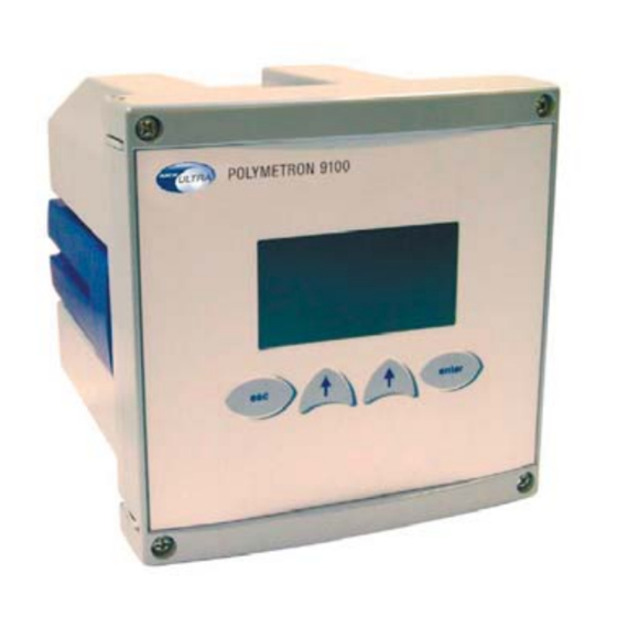
POLYMETRON 9125
Conductivity/resistivity measurement
По вопросам продаж и поддержки обращайтесь:
Астана +7(77172)727-132, Волгоград (844)278-03-48, Воронеж (473)204-51-73, Екатеринбург (343)384-55-89,
Казань (843)206-01-48, Краснодар (861)203-40-90, Красноярск (391)204-63-61, Москва (495)268-04-70,
Нижний Новгород (831)429-08-12, Новосибирск (383)227-86-73, Ростов-на-Дону (863)308-18-15,
Самара (846)206-03-16, Санкт-Петербург (812)309-46-40, Саратов (845)249-38-78, Уфа (347)229-48-12
221=191=025 - Revision L - 23/02/2007
Единый адрес: hca@nt-rt.ru
Веб-сайт: hach.nt-rt.ru
Advertisement
Table of Contents

Related Manuals for Hach POLYMETRON 9125


Summary of Contents for Hach POLYMETRON 9125
- Page 1 Operator Manual POLYMETRON 9125 Conductivity/resistivity measurement По вопросам продаж и поддержки обращайтесь: Астана +7(77172)727-132, Волгоград (844)278-03-48, Воронеж (473)204-51-73, Екатеринбург (343)384-55-89, Казань (843)206-01-48, Краснодар (861)203-40-90, Красноярск (391)204-63-61, Москва (495)268-04-70, Нижний Новгород (831)429-08-12, Новосибирск (383)227-86-73, Ростов-на-Дону (863)308-18-15, Самара (846)206-03-16, Санкт-Петербург (812)309-46-40, Саратов (845)249-38-78, Уфа (347)229-48-12 Единый...
- Page 2 - 73/23/CEE modified by the directive 93/68/CEE Warning ! There are no user-serviceable parts in either the transmitter or sensor. Only Hach Ultra Analytics personnel or their authorized representative should attempt repair of the system and only components expressly approved by the manufacturer should be used.
-
Page 3: Table Of Contents
Transmitter 9125 – Conductivity / resistivity measurement Table of contents 1. General presentation of the conductivity / resistivity measure system ....................3 Presentation of the 9125 transmitter ................3 Introduction........................4 Conductivity measurement ....................4 Characteristics........................6 2. Installation of the transmitter ............11 Unpacking of the transmitter 9125 ................. - Page 4 Transmitter 9125 – Conductivity / resistivity measurement 1 point calibration ................. 32 Execution of a 2 point calibration ............33 TDS measure calibration .................. 34 Temperature electric calibration / Resistor adjust ........ 35 Process calibration ................35 PARAMETERS Menu..................... 36 HISTORIC Menu ......................
-
Page 5: General Presentation Of The Conductivity / Resistivity Measure System
Transmitter 9125 – Conductivity / resistivity measurement General presentation of the conductivity / resistivity measure system Presentation of the 9125 transmitter The 9125 transmitter and associated measuring sensors has been designed for measuring and continuous control of conductivity and resistivity (with possibility of temperature measurement) in industrial process. -
Page 6: Introduction
Transmitter 9125 – Conductivity / resistivity measurement Introduction The 9125 transmitter is a user-friendly instrument (installation, programming), equipped with microprocessor it can be configured to correspond to any application in the following sectors : drinking water, waste water, process (chemistry, paper mills, sugar mills...), measurement in pure/ultrapure water (energy power plants, semiconductor industry, chemistry). - Page 7 Transmitter 9125 – Conductivity / resistivity measurement Mobility of these species in an electric field depends naturally on their size, weight, transport charge, viscosity of the field. The greater the concentration of the species is, the greater the interactions between these ionic species is.
-
Page 8: Characteristics
Transmitter 9125 – Conductivity / resistivity measurement Characteristics The 9125 is equipped with an input measurement channel : a conductivity probe, 2 electrodes and inductive may be connected as well as a temperature Pt100 or Pt1000 probe. The 9125 is also equipped with 2 analogue outputs (0 or 4-20 mA). - Page 9 Transmitter 9125 – Conductivity / resistivity measurement Connections 2,5 mm screw terminals Fuse 5 x 20 mm Cartridge T2AL - 250 V Consumption 25 VA European standards EN 61326-1997 and EN61326 A1-1998 (Industrial level for immunity) EN- 61010-1 UL and CSA agreement File E226594 MECHANICAL CHARACTERISTICS Dimensions...
- Page 10 Transmitter 9125 – Conductivity / resistivity measurement Inductive probe Cell constant Resistivity range 1 cm 1 .cm...10 k .cm 2,35 cm 0,5 .cm...5 k .cm 10 cm 0,1 .cm...1 k .cm Ambient temperature -20°C...+200°C (-4…392 °F) range Display resolution Conductivity/resistivity : automatic point drift (min. resolution 0.001 S/cm) <...
- Page 11 Transmitter 9125 – Conductivity / resistivity measurement Temperature calibration 20 °C ( 36 °F) ANALOGUE OUTPUT Output signals 2 galvanicly outputs insulated Allocation Conductivity/resistivity/temperature Type 0 ... 20 mA 4 ... 20 mA Mode Linear Dual Logarithmic Maximum load Accuracy 0.1 mA ALARMS Alarm number...
- Page 12 Transmitter 9125 – Conductivity / resistivity measurement PROGRAMMING Language French English German Italian Spanish Dutch Display Icones + graphic zone (80*64 pixels) Calibration Protection codes Programming Service Page 10...
-
Page 13: Installation Of The Transmitter
Transmitter 9125 – Conductivity / resistivity measurement Installation of the transmitter Unpacking of the transmitter 9125 Inspect the package at the reception to detect an eventual damage due to the transport. Make sure the package contents are not damaged. Check if the package corresponds to your order : quantity delivered, type of instrument and version accordingly to the instruction plates,... -
Page 14: Dimensions
Transmitter 9125 – Conductivity / resistivity measurement Dimensions (Dimensions are in mm [inches]). Fig. 2.1 Transmitter 9125 dimension Page 12... -
Page 15: Mounting Types
Transmitter 9125 – Conductivity / resistivity measurement Mounting types 3 possibilities to mount the instrument (use of the red clamping bow) : The transmitter housing conforms to norm DIN 43700. Panel mounting : Panel cutting : 138 x 138 mm Front panel dimensions : 144 x 144 mm 2 screws 4 mm lg 16 flat head (provided) for... - Page 16 Transmitter 9125 – Conductivity / resistivity measurement Wall mounting : 2 screws 4 mm lg 60 flat head (not provided)/ 80 mm center distance Fig. 2.3 Wall mounting Page 14...
- Page 17 Transmitter 9125 – Conductivity / resistivity measurement Pipe mounting : 2" maximum - 2 screws 4 mm lg 60 (provided) Fig. 2.4 Vertical mounting Fig. 2.5 Horizontal mounting Page 15...
-
Page 19: Electric Connections
Transmitter 9125 – Conductivity / resistivity measurement Electric connections Electronic board lay-out in the 9125 transmitter enclosure ________________________________________________________________________ Fig. 3.1 Electronic board lay-out Terminal block 4-20 mA CPU board RS485 board (option) Relay board (option) Choice between an inductive (all 4 switches on position I) or a 2 electrode (Kohlraush) probe (all 4 switches on position K) Programmed EEPROM Conductivity module... - Page 20 Transmitter 9125 – Conductivity / resistivity measurement ________________________________________________________________________ Fig. 3.2 9125 shielded plate Electric connections are realised on the terminal inside the housing. Put the cables into the appropriated openings. The main supply and relay cables should be dispatched via the openings behind the shielded plate.
- Page 21 Transmitter 9125 – Conductivity / resistivity measurement ________________________________________________________________________ Fig. 3.3 Power and relays connections 1. Terminal block connections Analogue outputs 4-20 mA 2. Terminal block connections "option RS 485" 3. Terminal block connections of the conductivity sensors 4-20 mA 4. Earth Sensor Page 19...
-
Page 22: Main Connection
Transmitter 9125 – Conductivity / resistivity measurement Main connection Electrical connection should be performed only by qualified personnel. For the base model, the power supply accepts 100-240 VAC 10 %, (50/60 Hz) without changes in configuration. Before switching the transmitter, make sure the site voltage corresponds to the instrument voltage indicated on the identification plate. -
Page 23: Relays Connections
Transmitter 9125 – Conductivity / resistivity measurement Relays connections The 9125 is equipped with 4 relays. Relay S4may be configured as a temporized relay. The nominal value of the cutoff current of each relay is 2A for 250 Vca or 0,5 A for 100 Vcc. -
Page 24: Sensor Connections
TEMP- black yellow white white brown internal internal shield shield (X2) external external shield shield Use only Hach Ultra Analytics supplied cables. Using other types of cables does not ensure the conformity to the electromagnetic compatibility standards. Page 22... -
Page 25: Using The 9125 Transmitter
Transmitter 9125 – Conductivity / resistivity measurement Using the 9125 transmitter Utilization rules for the menus The user interface of the 9125 transmitter is made of a display screen and 4 keys. The (Esc) key is used to go back to the previous menu. -
Page 26: Modification Of A Value
Transmitter 9125 – Conductivity / resistivity measurement Modification of a value The highlighted digit may be modified with the key . Each digit can be validated by pressing ENTER. Repeat both operations for each digit. Note : If you do not use the display for at least 10 minutes, instrument returns... -
Page 27: Main Display
Transmitter 9125 – Conductivity / resistivity measurement Main display 26.8 26.8 mS/cm : conductivity measurement 25.0 °C : temperature measurement S1...S4 : alarm status (invisible if alarm inactive). mS/cm 25.0°C Disp2 Menu Display 2 S1 : °C > 30.0 S1...S4 : alarm status S2 : OK S1 : activated by a temperature >... -
Page 28: Display Options
Transmitter 9125 – Conductivity / resistivity measurement Display options Choice of the language English is the default language. You can choose an MENU other language available (French, German, Italian, Spanish or Dutch) by following the procedure below : CALIBRATION MAINTENANCE Use the right function key MENU. -
Page 29: Unit Choice
Transmitter 9125 – Conductivity / resistivity measurement UNIT choice As the language used, it’s possible to choose the units of the measures in which they will be display. Unit. allows to choose one of the units in DISPLAY conductivity or resistivity in which values will be S/cm done. -
Page 30: Concentration Measure (Tds)
Transmitter 9125 – Conductivity / resistivity measurement Concentration measure (TDS) The Total Dissolved Solid (TDS) measure is a concentration measure in the limits of measure where, for a part given, the concentration of the solution is proportional to its conductivity. The next board show for the mains solutions, the relations existing... -
Page 31: Programming The Transmitter
Transmitter 9125 – Conductivity / resistivity measurement Programming the transmitter Main menu The main menu gives access to 4 main functions of MENU the instrument : CALIBRATION The CALIBRATION menu enables to adjust the MAINTENANCE instrument measurement according PROGRAMMING reference measurements. SERVICE The MAINTENANCE menu enables to intervene Select... -
Page 32: Calibration Menu
Transmitter 9125 – Conductivity / resistivity measurement Calibration Menu MENU Note : CALIBRATION ETALONNAGE Before any calibration launching, check the MAINTENANCE parameters of the MEASURE menu (probe type, PROGRAMMING temp. Comp.) Are correctly configured. SERVICE Select (See page 25). CALIBRATION This option allows to calibrate the conductivity measure, the temperature measure and to display the CALIB. -
Page 33: Type Of Calibration
Transmitter 9125 – Conductivity / resistivity measurement Type of calibration COND. CALIB. With a 2 electrode probe TYPE : Elect. For the first point, remove the probe from liquid or R = 200 unscrew the connector from the probe. Select For the second point connect a resistance to the IN/OUT terminal of the conductivity module. -
Page 34: Point Calibration
Transmitter 9125 – Conductivity / resistivity measurement COND. CALIB. 2 point calibration For the first point, remove the probe from liquid or 2 pts TYPE : unscrew the connector from the probe (2 electrode probe) in a known concentration solution. The user enters this solution value when calibrating. -
Page 35: Execution Of A 2 Point Calibration
Transmitter 9125 – Conductivity / resistivity measurement EXECUTION COND. CALIB. EXECUTION EXECUTION Execution of a 2 point calibration PROGRAMMING Program the manual 2 point calibration and execute it as follows : Select Remove the electrode from liquid. When the measure is stable, the instrument goes automatically to next step. -
Page 36: Tds Measure Calibration
Transmitter 9125 – Conductivity / resistivity measurement TDS measure calibration This option is available only if you have selected the measurement TDS in the menu DISPLAY. Select with the function key Choice CALIB TDS in the menu CALIBRATION and press ENTER. This calibration permits to adjust the coefficient CALIBRATION between... -
Page 37: Temperature Electric Calibration / Resistor Adjust
Transmitter 9125 – Conductivity / resistivity measurement Temperature electric calibration / Resistor adjust TEMP. CALIB This calibration is factory realised. Elect. TYPE : Used to realise an electric calibration for the Pt100 RES1 : 100 measurement. 2 resistances of known values should be connected to the temp + and temp - of the module measure. -
Page 38: Parameters Menu
Transmitter 9125 – Conductivity / resistivity measurement PARAMETERS Menu This menu displays the calibration parameters of the PARAMETERS conductivity measurement. DATE : 01/01/01 Date of last calibration. This date is the date the user SLOPE : 100% has entered after a conductivity calibration ( electric, 2 COEFF : 0.50 points, 1 point). -
Page 39: Maintenance Menu
Transmitter 9125 – Conductivity / resistivity measurement MAINTENANCE Menu MAINTENANCE When changing or cleaning a probe or servicing the instrument, the transmitter continues to display 6.98 measures. mS/cm 26.4°C The analogue output value is the value programmed in the mA menu. The relay status is not modified. Page 37... -
Page 40: Programming Menu
Transmitter 9125 – Conductivity / resistivity measurement PROGRAMMING Menu PROGRAMMATION PROGRAMMING Note : MEASURE MESURE MESURE MESURE Warning ! An access code may be required if SORTIES mA mA OUTPUTS programmed. ALARMES ALARMS RS485 RS485 This menu enables the configuration of the instrument Select Choix according to its application. -
Page 41: S/Measure Menu
Transmitter 9125 – Conductivity / resistivity measurement MEASURE S/MEASURE Menu The PROBE menu allows to configurate the utilized PROBE probe type, TEMP. COMP. temperature TEMP. COMP. compensation, TDS the TDS measure coefficient 0.50 TDS : when it is actived. Select PROBE PROBE 2 elect. -
Page 42: Temperature Compensation
Transmitter 9125 – Conductivity / resistivity measurement TEMPERATURE COMPENSATION MEASURE : - No Choice temperature TEMP. COMP. measurement with without - Pt 100 Pt100 MEASURE : Pt100 / Pt1000. - Pt1000 TYPE : Manual TYPE : - No Choice between no temperature TEMP. -
Page 43: S/Ma Outputs Menu
Transmitter 9125 – Conductivity / resistivity measurement S/mA OUTPUTS Menu mA OUPUTS This menu allows to adjust analogue outputs. OUTPUT 1 OUTPUT 2 SPECIAL PROG. TEST Select Page 41... -
Page 44: Output 1/2
Transmitter 9125 – Conductivity / resistivity measurement OUTPUT 1/2 OUTPUT 1/2 AFFECT. : AFFECT. : choice analogue output TYPE : 0/20 mA allocated to measure or temperature. MODE : Dual LOWER : 10.0 mS °C/°F MIDD : 15.0 mS UPPER : 20.0 mS TYPE : choice of the analogue output type. -
Page 45: S/Alarms Menu
Transmitter 9125 – Conductivity / resistivity measurement S/ALARMS menu ALARMS This sub-menu allows to reach the configuration of ALARM 1 alarms 1 to 4. ALARM 2 ALARM 3 ALARM 4 Select allows to choose the operating The MODE parameter ALARM 3 mode of the 4 alarms : System MODE : Syst... -
Page 46: Alarm 1/2 (Limit)
Transmitter 9125 – Conductivity / resistivity measurement ALARM 1/2 (limit) AFFECT. : choice of a limit on the measurement ALARM 1 or on the temperature. °C/°F AFFECT. : Non LIMIT : 20.3°C DIR. : Up °C/°F DELAY : 30s HYST. : 10% LIMIT : value of the limit. -
Page 47: Usp Mode
Transmitter 9125 – Conductivity / resistivity measurement The TAB menu is used to configure the stored USP curve: W.F.I. (Water For Injection) or P.W. (Pure Water). USP mode USP is a standard used in the pharmaceutical industry. It recommends the use of a non temperature- compensated conductivity measurements and sets the upper limits of acceptable conductivity for USP- compliant water according to temperature. - Page 48 Transmitter 9125 – Conductivity / resistivity measurement Example: if the measured temperature is equal to 22°C, the threshold is of 1.1 S/cm and shall remain at this value as long as the temperature stays at 22°C. If the temperature varies, rising to 25°C, the threshold automatically switches to 1.3 S/cm.
-
Page 49: Alarm 3 (Alarm System)
Transmitter 9125 – Conductivity / resistivity measurement ALARM 3 (Alarm system) ALARM 3 In case of an alarm 3, choice between a limit System MODE : Syst alarm or alarm system function. ACCEPT : Manu MODE : RELAY : NO Limit System Select... -
Page 50: S/Special Prog. Menu
Transmitter 9125 – Conductivity / resistivity measurement SPECIAL PROG. S/SPECIAL PROG. Menu MAINTENANCE This screen allows to adjust 4..20 mA outputs states in special events : CALIBRATION SYST. ALARM MAINTENANCE CALIBRATION Select SYST. ALARM MODE : choice preset value during SPECIAL PROG. -
Page 51: S/Rs485 Menu
Transmitter 9125 – Conductivity / resistivity measurement S/RS485 Menu This option requires the RS485 kit. RS485 N° Monec number (0...32) N° : 4 BAUD : 9600 BAUD 300/600/1200/2400/4800/9600/19200 Transmission speed in bauds PARIT. : odd BIT STOP : 1 PARIT. - Without parity bit : No SWAP WORD : NO - With odd parity bit : Odd... -
Page 52: Service Menu
Transmitter 9125 – Conductivity / resistivity measurement SERVICE Menu SERVICE Note : POLARIZATION An access code may be required if it has been AVERAGE programmed. DISPLAY CODE This screen allows to reach the 9125 transmitter SOFT ISSUE configuration screens. DEFAULT VAL.. The display options are detailed page 26. -
Page 53: S/Polarization Menu
Transmitter 9125 – Conductivity / resistivity measurement S/POLARIZATION Menu POLARIZATION This menu is displayed only if you use a 2 electrode CABLE CAP. CAP. CABLE probe. TEST Select CABLE CAP. CABLE CAP. CABLE measure the electrode cable capacity. CAPACITY It is mandatory to disconnect the probe connector to measure the capacity or to make an electric 1.02 nF calibration. -
Page 54: S/Average Menu
Transmitter 9125 – Conductivity / resistivity measurement S/AVERAGE Menu AVERAGE S/AVERAGE menu program a moving average on the AVERAGE : 9 measurement. TEST : TEST : Select AVERAGE : define the number of measures to calculate the average. TEST : visualize the difference between a measure TEST done with or without average. -
Page 55: S/Code Menu
Transmitter 9125 – Conductivity / resistivity measurement S/CODE Menu CODE 0000 CALIB. : access code for temperature and CALIB. : conductivity calibrations menu. PROG. : 0000 SERVICE : 0000 PROG. : access code for "Programming" menu. Select SERVICE : access code for "service" menu. Note : If you have forgotten your access code, press simultaneously ESC and ENTER to enter into the... -
Page 56: S/Soft Issue Menu
Transmitter 9125 – Conductivity / resistivity measurement S/SOFT ISSUE Menu SOFT ISSUE The transmitter displays the type of instrument and the MONEC 9125 software version installed. Cond X.XX S/DEFAULT/VALUES Menu DEFAULT/VAL. Loading Note : values If you press YES, you load the default values and default ? you loose the programmed values and the calibration parameters. -
Page 57: S/Ma Adjust Menu
Transmitter 9125 – Conductivity / resistivity measurement S/mA ADJUST Menu mA ADJUST This menu adjustment of the analogue outputs to OUTPUT 1 20 mA with internal coefficient between -9999...9999. OUTPUT 2 Select OUTPUT 1/2 VALUE : 0000 S/FACTORY Menu Factory code necessary. The user has no access to this menu. -
Page 59: Polarization
Transmitter 9125 – Conductivity / resistivity measurement Polarization Electric representation of the probe and its cable In a conductivity measurement with a 2 electrode probe the measurement current is transmitted via the electrodes. The current is ensured by electrons in the electrodes and by ionic migration in the solution measured. -
Page 60: Frequency Adjustment According To The Conductivity Measurement
Transmitter 9125 – Conductivity / resistivity measurement where : The dipole Rp, Cp represents the active and reactive part of the energy necessary to the electron exchange between the sample and the electrodes. and : Cc : the cable capacity Frequency adjustment according to the conductivity measurement Probe 8317 (K=1) -
Page 61: Automatic Adjustment Of The Frequency
Transmitter 9125 – Conductivity / resistivity measurement measuring range 100 μS/cm to 1 mS/cm : In this measuring range the cable capacity or the polarization are negligible and do not perturb conductivity measurement. measuring range 1 mS/cm to 20 mS/cm : When the measuring frequency is low, the polarization becomes important and induces an error in the conductivity measurement. -
Page 63: Error Messages
Transmitter 9125 – Conductivity / resistivity measurement Error messages Note : In manual acquittal, in order to suppress an error message press ENTER after correcting the default. ERROR MESSAGE DESCRIPTION/POSSIBLE CAUSE 10.3 Sensor not correctly connected Temperature sensor damaged Replace it if necessary. mS/cm Pt100/Pt1000 SHORT CIRCUIT... - Page 64 Transmitter 9125 – Conductivity / resistivity measurement ERROR MESSAGES DURING A CALIBRATION Note : Press ESC to leave the menu and calibrate again. COND. CALIB. The electronic zero shift is superior to the limit programmed. Calibrate again. OFFSET OUT OF LIMITS COND.
-
Page 65: Appendix A : Default Values
Transmitter 9125 – Conductivity / resistivity measurement Appendix A : Default values CALIBRATION COND. CALIB. PARAMETERS TYPE : Electr. DATE : 01/01/01 SLOPE : 100.0% RES. : 1000 : 0.0°C TEMP. CALIB. TYPE : Process PROGRAMMING MEASURE PROBE TEMP. COMP. TYPE : 2 elect. - Page 66 Transmitter 9125 – Conductivity / resistivity measurement SPECIAL PROG. CALIBRATION MAINTENANCE MODE : Last MODE : Last TIMER SYST. ALARM MODE : Last MODE : Last RS485 BAUD : 19200 PARITY : No STOP BIT : 1 SWAP WORD SERVICE AVERAGE AVERAGE : 1 DISPLAY...
-
Page 67: Appendix B : Spare Parts List
Transmitter 9125 – Conductivity / resistivity measurement Appendix B : Spare parts list No other spare parts except those below in the table should be replaced in the instrument. Part number Description 09125=A=1001 9125 equipped CPU board 09125=A=1500 9125 complete conductivity module 09125=A=2000 9125 power supply (standard version) 09125=A=2020... - Page 68 По вопросам продаж и поддержки обращайтесь: Астана +7(77172)727-132, Волгоград (844)278-03-48, Воронеж (473)204-51-73, Екатеринбург (343)384-55-89, Казань (843)206-01-48, Краснодар (861)203-40-90, Красноярск (391)204-63-61, Москва (495)268-04-70, Нижний Новгород (831)429-08-12, Новосибирск (383)227-86-73, Ростов-на-Дону (863)308-18-15, Самара (846)206-03-16, Санкт-Петербург (812)309-46-40, Саратов (845)249-38-78, Уфа (347)229-48-12 Единый адрес: hca@nt-rt.ru Веб-сайт: hach.nt-rt.ru...
Need help?
Do you have a question about the POLYMETRON 9125 and is the answer not in the manual?
Questions and answers