Table of Contents
Advertisement
Quick Links
Programmable Logic Controllers
CC-Link Master Module
Art. no.: 168595
15 03 2007
JY992D93101
Version D
MELSEC FX Series
User's Manual
(Hardware)
Industrial automation
Elincom Group
European Union: www.elinco.eu
Russia: www.elinc.ru
FX2N-16CCL-M
MITSUBISHI ELECTRIC
MITSUBISHI ELECTRIC
INDUSTRIAL AUTOMATION
Advertisement
Table of Contents
Troubleshooting

Subscribe to Our Youtube Channel
Related Manuals for Mitsubishi FX2N-16CCL-M


Summary of Contents for Mitsubishi FX2N-16CCL-M
- Page 1 MITSUBISHI ELECTRIC MELSEC FX Series Programmable Logic Controllers User's Manual (Hardware) Industrial automation Elincom Group European Union: www.elinco.eu Russia: www.elinc.ru FX2N-16CCL-M CC-Link Master Module Art. no.: 168595 15 03 2007 INDUSTRIAL AUTOMATION MITSUBISHI ELECTRIC JY992D93101 Version D...
- Page 2 • If in doubt about the operation or use of FX -16CCL-M CC-Link System Master Block please consult the nearest Mitsubishi Electric distributor. • This manual is subject to change without notice.
- Page 3 FX2N-16CCL-M CC-Link System Master Block -16CCL-M Control & Communication-Link System Master Block USER’S MANUAL Manual number : JY992D93101 Manual revision : D Date : March 2007...
- Page 4 FX2N-16CCL-M CC-Link System Master Block...
- Page 5 FX2N-16CCL-M CC-Link System Master Block FAX BACK Mitsubishi has a world wide reputation for its efforts in continually developing and pushing back the frontiers of industrial automation. What is sometimes overlooked by the user is the care and attention to detail that is taken with the documentation. However, to continue this process of improvement, the comments of the Mitsubishi users are always welcomed.
- Page 6 FX2N-16CCL-M CC-Link System Master Block...
- Page 7 FX2N-16CCL-M CC-Link System Master Block Guidelines for the Safety of the User and Protection of the FX -16CCL-M CC- Link System Master Block This manual provides information for the use of the FX -16CCL-M CC-Link System Master Block. The manual has been written to be used by trained and competent personnel. The definition of such a person or persons is as follows;...
- Page 8 FX2N-16CCL-M CC-Link System Master Block • Under no circumstances will Mitsubishi Electric be liable responsible for any consequential damage that may arise as a result of the installation or use of this equipment. • All examples and diagrams shown in this manual are intended only as an aid to understanding the text, not to guarantee operation.
-
Page 9: Table Of Contents
FX2N-16CCL-M CC-Link System Master Block Contents 1. Introduction....................1-1 1.1 Associated Manuals .................... 1-1 1.2 General Names and Abbreviations..............1-2 2. Overview ....................2-1 2.1 Overview of CC-Link System................2-1 2.2 Overview of CC-Link Master Block FX -16CCL-M..........2-1 2.3 Characteristics ..................... 2-2 2.4 Major Differences from A/QnA/Q Series.............. - Page 10 FX2N-16CCL-M CC-Link System Master Block Contents 5. Functions ....................5-1 5.1 Function List ......................5-1 5.2 Communication between Master Station and Remote I/O Stations..... 5-2 5.3 Communication between Master Station and Remote Device Stations ....5-4 5.4 Communication in Compound System ..............5-9 5.5 Reserved Station Function ................
- Page 11 FX2N-16CCL-M CC-Link System Master Block Contents 8. Data Link Procedure................8-1 8.1 Data Link Procedure .................... 8-3 8.2 Name of Each Part and Settings ................. 8-4 8.3 Master Block Status Check (Hardware Test)............8-8 8.4 Module Wiring with Dedicated CC-Link Cables ........... 8-9 8.5 T-shaped Branch Connection Using Dedicated CC-Link Cables ......
- Page 12 FX2N-16CCL-M CC-Link System Master Block Contents 12.Communication in Compound System ..........12-1 12.1 System configuration ..................12-1 12.1.1 Setting of master station..................12-1 12.1.2 Setting of remote I/O station..................12-2 12.1.3 Setting of remote device station ................12-2 12.2 Creating a Program ................... 12-3 12.2.1 Program for parameters ..................
-
Page 13: Introduction
FX2N-16CCL-M CC-Link System Master Block Introduction 1 Introduction Associated Manuals Table 1.1: Manual name Manual number Description ★ -16CCL-M JY992D93201 Describes the name of each part and handling of (packed with product) the CC-Link master block FX -16CCL-M. User’s Guide ★... -
Page 14: General Names And Abbreviations
FX2N-16CCL-M CC-Link System Master Block Introduction 1 General Names and Abbreviations Unless otherwise specified, this manual uses the general names and abbreviations shown in the table below to describe the CC-Link system master block FX -16CCL-M. Table 1.2: General name/... -
Page 15: Overview
FX2N-16CCL-M CC-Link System Master Block Overview 2 Overview This chapter describes the overview of the CC-Link system master block FX -16CCL-M for the FX Series PLC. The abbreviated term "CC-Link" stands for "Control & Communication-Link". "CC-Link" is used hereafter in this manual. -
Page 16: Characteristics
FX2N-16CCL-M CC-Link System Master Block Overview 2 Characteristics This section describes the characteristics of the CC-Link. 1) Communication with remote I/O station The switch ON/OFF status and the lamp ON/OFF status are communicated using remote inputs (RX) and remote outputs (RY). - Page 17 FX2N-16CCL-M CC-Link System Master Block Overview 2 3) System down prevention (slave station cutoff function) Because the system employs the bus method, even if there is a remote station which goes down due to power OFF, etc., it will not affect the communication with other functioning stations.
- Page 18 FX2N-16CCL-M CC-Link System Master Block Overview 2 5) Error invalid station function A station which cannot execute the data link because the power is turned off, etc. can be excluded from being handling as a "data link faulty station" in the master station.
- Page 19 FX2N-16CCL-M CC-Link System Master Block Overview 2 6) Parameter registration to the EEPROM By registering the parameters to the EEPROM in advance, the parameter settings do not have to be executed at each startup (power OFF → ON) of the master station.
-
Page 20: Major Differences From A/Qna/Q Series
FX2N-16CCL-M CC-Link System Master Block Overview 2 Major Differences from A/QnA/Q Series Table 2.1: Item FX Series master block A/QnA/Q Series master module • Master station Applicable function • Master station • Local station • Standby master station • Remote I/O stations: 64 max. -
Page 21: System Configuration
FX2N-16CCL-M CC-Link System Master Block System Configuration 3 System Configuration This chapter describes the system configuration for the CC-link in which an FX Series PLC functions as the master station. Total Configuration Up to 7 remote I/O stations and up to 8 remote device stations can be connected to one FX Series PLC functioning as the master station. -
Page 22: Applicable Plc
FX2N-16CCL-M CC-Link System Master Block System Configuration 3 When using a FX , FX or a FX 1) Connection of remote I/O stations (up to 7 stations) Number of I/O points in PLC (including vacant points numbers and extension I/O points) -
Page 23: Configuration Example
FX2N-16CCL-M CC-Link System Master Block System Configuration 3 Configuration Example 3.3.1 Example of maximum configuration, when using a FX 16 points 8 points [7 remote I/O stations] 32 points x 7 stations Main unit Master block -16M -16CCL-M Occupies 1... -
Page 24: Scan Time Of Plc And Connection Of Two Or More Master Blocks
FX2N-16CCL-M CC-Link System Master Block System Configuration 3 3.3.2 Scan time of PLC and connection of two or more master blocks 1) Measured scan time - Configuration: Series PLC main unit]+[FX -16CCL-M]+[7 remote I/O stations]+[8 remote device stations] - Number of link device points: 110 words The scan time in the configuration above is 125 ms. -
Page 25: Example Of Connection Of Two Or More Fx Series Plcs
FX2N-16CCL-M CC-Link System Master Block System Configuration 3 3.3.3 Example of connection of two or more FX Series PLCs When connecting two or more FX Series PLCs in the CC-Link system, connect CC-Link interface blocks FX -32CCL on the child station side and use them as remote device stations. -
Page 26: Example Of Connection To The Cc-Link System For The A/Qna/Q Series
FX2N-16CCL-M CC-Link System Master Block System Configuration 3 3.3.4 Example of connection to the CC-Link system for the A/QnA/Q Series When connecting the CC-Link system for the A/QnA/Q Series and the CC-Link system for the FX Series, provide the CC-Link interface FX -32CCL in the connection area as shown in the figure below. -
Page 27: Number Of Occupied Stations And Station Numbers As Well As Number Of Modules And Number Of Stations
FX2N-16CCL-M CC-Link System Master Block System Configuration 3 Number of Occupied Stations and Station numbers as well as Number of Modules and Number of Stations This section describes the relationship between the number of occupied stations and the station as well as between the number of modules and the number of stations. -
Page 28: System Equipment List
FX2N-16CCL-M CC-Link System Master Block System Configuration 3 System Equipment List The table below shows the list of equipment constructing the CC-Link for the FX Series PLC. Table 3.3: Number of Station Product name Model name Description occupied type stations Master ⎯... - Page 29 FX2N-16CCL-M CC-Link System Master Block System Configuration 3 Table 3.3: Number of Station Product name Model name Description occupied type stations 1-line, 8-point DC input module (sink/source shared) AJ65SBTB1-8D 24V DC, 7 mA, 8 points/common 1-line, 16-point DC input module (sink/source shared)
- Page 30 FX2N-16CCL-M CC-Link System Master Block System Configuration 3 Table 3.3: Number of Station Product name Model name Description occupied type stations I/O module, waterproof type Input: Waterproof, 4-line, 8 DC input points (sink) Small type Remote 24V DC, 5 mA, 16 points/common...
-
Page 31: Precautions When Configuring The System
FX2N-16CCL-M CC-Link System Master Block System Configuration 3 Precautions When Configuring the System 3.6.1 Wiring of power supply When the FX -16CCL-M is supplied with 24V DC, the external power supply of FX -16CCL-M needs to be supplied at same time as the PLC main unit. See examples below. -
Page 32: Wiring Of Remote I/O Modules
FX2N-16CCL-M CC-Link System Master Block System Configuration 3 3.6.2 Wiring of remote I/O modules Design the system with the following considerations to prevent erroneous inputs from remote I/O modules: 1) Timing of power ON and power OFF Turn on the power of remote I/O modules first, then start the data link. - Page 33 FX2N-16CCL-M CC-Link System Master Block System Configuration 3 b) Countermeasures against erroneous input Wire the module power supply, the stabilized power supply and the input external power supply from the same power source. Main unit Remote I/O module For DC input...
- Page 34 FX2N-16CCL-M CC-Link System Master Block System Configuration 3 MEMO 3-14...
-
Page 35: Specification
FX2N-16CCL-M CC-Link System Master Block Specification 4 Specification DESIGN PRECAUTIONS • Refer to Chapter 13 in this manual for the status of each station when a communication error occurred in the data link. • When executing control (data changes) to an operating PLC, construct an interlock circuit in the sequence program so that the entire system always works conservatively. -
Page 36: Performance Specification
FX2N-16CCL-M CC-Link System Master Block Specification 4 Performance Specification Table 4.1: Item Specification Master station function (The local station and standby master station functions Applicable function are not provided.) CC-Link version Ver.1.10 Selectable (by rotary switch) among 156 kbps, 625 kbps, 2.5 Mbps, 5 Mbps... - Page 37 FX2N-16CCL-M CC-Link System Master Block Specification 4 Table 4.1: Item Specification Connection cable Dedicated CC-Link cable/Dedicated high-performance CC-Link cable • Automatic return function RAS function • Slave station cutoff function • Error detection by link special relay/register Number of times of...
-
Page 38: Maximum Transmission Distance
FX2N-16CCL-M CC-Link System Master Block Specification 4 4.4.1 Maximum transmission distance This section describes the relationship between the transmission speed and the maximum transmission distance. 1) In the system consisting of only remote I/O stations and remote device stations Remote I/O station... -
Page 39: Dedicated Cc-Link Cable
FX2N-16CCL-M CC-Link System Master Block Specification 4 Dedicated high-performance CC-Link cable (for the CC-Link system V 1.10) (requiring terminal resistor of 130 Ω) When the entire system consists of only equipment and cables V 1.10, the following advantages are offered. -
Page 40: Buffer Memory
FX2N-16CCL-M CC-Link System Master Block Specification 4 Buffer Memory The buffer memory is used to swap data between the master block and the PLC. In the PLC, the FROM/TO instructions are used to read/write data. The contents of the buffer memory return to the default values when the power is turned off. -
Page 41: Buffer Memory List
FX2N-16CCL-M CC-Link System Master Block Specification 4 4.6.1 Buffer memory list Table 4.5: BFM number Read/write Item Description Reference possibility Hex. Dec. Parameter Stores the information (parameters) Read/write 4.6.2 information area to execute the data link. enabled Read/write I/O signal I/O signals to control the master block 4.6.3... - Page 42 FX2N-16CCL-M CC-Link System Master Block Specification 4 4.6.2 Parameter information area Set the conditions to perform the data link. The contents of setting can be registered to the EEPROM. Table 4.6: number Item Description Default Hex. Dec. ⎯ ⎯ (Prohibited to use)*...
- Page 43 FX2N-16CCL-M CC-Link System Master Block Specification 4 a) Number of connected modules Set the number of remote station modules (including reserved stations) connected to the master station. This is not a station count. The setting range is "1 to 15 (modules)".
- Page 44 FX2N-16CCL-M CC-Link System Master Block Specification 4 Setting example: When setting a remote device station with the station No. 4 and a remote station with the station No. 9 as reserved in the system configuration below. Stations to be connected in the future Station No.
- Page 45 FX2N-16CCL-M CC-Link System Master Block Specification 4 g) Station information Set the station type for connected remote stations and reserved stations. 1) The figure below shows the data configuration to be set. Number of occupied Station type Station No. stations 1: Occupies 1 station.
-
Page 46: I/O Signals To Plc
FX2N-16CCL-M CC-Link System Master Block Specification 4 4.6.3 I/O signals to PLC This section describes I/O signals used to control the master block. The signals used to control the master block are assigned to the buffer memory (BFM#A BFM#B ) built in the FX -16CCL-M. - Page 47 FX2N-16CCL-M CC-Link System Master Block Specification 4 Table 4.9: PLC → Master block Write (when TO instruction is used) Write Reference: Output number Output signal name number in A/QnA/Q Series Refresh command (Prohibited to use) Request for module reset (Prohibited to use)
- Page 48 FX2N-16CCL-M CC-Link System Master Block Specification 4 Table 4.10: PLC ← Master block Read (when FROM instruction is used) Read Reference: Input number Signal name number in A/QnA/Q Series X(n+1)0 X(n+1)1 X(n+1)2 X(n+1)3 X(n+1)4 X(n+1)5 X(n+1)6 X(n+1)7 (Prohibited to use)
-
Page 49: I/O Signal Details
FX2N-16CCL-M CC-Link System Master Block Specification 4 4.6.4 I/O signal details This section describes the ON/OFF timing, the conditions, etc. of the I/O signals shown in Section 4.6.3. [Read signals] 1) Read module error: BFM#A Indicates whether the module is normal or not. - Page 50 FX2N-16CCL-M CC-Link System Master Block Specification 4 5) Read module reset acceptance completion: BFM#A Indicates the acceptance status of the request by the write request for module reset (BFM#A b4). This signal cannot be reset when the read module error is given (when BFM#A b0 is ON.).
- Page 51 FX2N-16CCL-M CC-Link System Master Block Specification 4 6) Read normal completion of data link startup by buffer memory parameters: BFM#A Indicates the normal completion status of the data link startup request by the write request for data link startup by buffer memory parameters (BFM#A b6).
- Page 52 FX2N-16CCL-M CC-Link System Master Block Specification 4 8) Read normal completion of data link startup by EEPROM parameters: BFM#A Indicates the normal completion status of the data link startup request by the write request for data link startup by EEPROM parameters (BFM#A b8).
- Page 53 FX2N-16CCL-M CC-Link System Master Block Specification 4 10)Read normal completion of parameter registration to EEPROM: BFM#A Indicates the normal completion status of the parameter (buffer memory address) registration to the EEPROM by the write request for parameter registration to EEPROM (BFM#A b10).
- Page 54 FX2N-16CCL-M CC-Link System Master Block Specification 4 12)Read module ready: BFM#A Indicates whether or not the module is ready for operation. a) The signal automatically turns ON when the module becomes ready for operation. b) The signal turns OFF when one of the following conditions occur: 1) There is an error in the module switch settings.
- Page 55 FX2N-16CCL-M CC-Link System Master Block Specification 4 14)Write request for module reset: BFM#A Resets the module. The module can be reset individually without resetting the PLC. For the signal timing, refer to 5). 15)Write request for data link startup by buffer memory parameters: BFM#A Starts up the data link in accordance with the contents of the parameters in the buffer memory.
-
Page 56: Master Block Control Signals
FX2N-16CCL-M CC-Link System Master Block Specification 4 4.6.5 Master block control signals 1) FROM/TO instruction access error judgement time: BFM#1C This buffer memory sets the period of time to judge FROM/TO instruction access errors in the unit of 10 ms. -
Page 57: Remote Input (Rx)
FX2N-16CCL-M CC-Link System Master Block Specification 4 4.6.6 Remote input (RX) - The input (RX) status from remote I/O stations and remote device stations is stored. - Each station uses 2 words. Remote I/O station Remote device station (Station No. 1: Occupies 1 station.) (Station No. - Page 58 FX2N-16CCL-M CC-Link System Master Block Specification 4 [Correspondence among buffer memory number in master station, station number and remote input (RX)] 4-24...
-
Page 59: Remote Output (Ry)
FX2N-16CCL-M CC-Link System Master Block Specification 4 4.6.7 Remote output (RY) - The output (RY) status to remote I/O stations and remote device stations is stored as below. - Each station uses 2 words. Remote I/O station Remote device station (Station No. - Page 60 FX2N-16CCL-M CC-Link System Master Block Specification 4 [Correspondence among buffer memory number in master station, station number and remote output (RY) number] 4-26...
-
Page 61: Remote Register (Rww) Master Station --> Remote Device Station
FX2N-16CCL-M CC-Link System Master Block Specification 4 4.6.8 Remote register (RWw) Master station --> Remote device station - The data transmitted to the remote register (RWw) in remote device stations is stored as below. - Each station uses 4 words. - Page 62 FX2N-16CCL-M CC-Link System Master Block Specification 4 [Correspondence among buffer memory number in master station, station number and remote register (RWw) number] Station Remote register Station Remote register number number number number number number RWw 0 RWw 20 RWw 1...
-
Page 63: Remote Register (Rwr) Master Station <-- Remote Device Station
FX2N-16CCL-M CC-Link System Master Block Specification 4 4.6.9 Remote register (RWr) Master station <-- Remote device station - The data transmitted from the remote register (RWr) in remote device stations is stored as below. - Each station uses 4 words. - Page 64 FX2N-16CCL-M CC-Link System Master Block Specification 4 [Correspondence among buffer memory number in master station, station number and remote register (RWr) number] Station Remote register Station Remote register number number number number number number RWr 0 RWr 20 RWr 1...
-
Page 65: Link Special Relay (Sb) And Link Special Register (Sw)
FX2N-16CCL-M CC-Link System Master Block Specification 4 4.6.10 Link special relay (SB) and link special register (SW) 1) Link special relay (SB) The data link status is stored in the form of bit ON/OFF information. Buffer memory addresses 5E0 to 5FF correspond to SB0000 to SB01FF. - Page 66 FX2N-16CCL-M CC-Link System Master Block Specification 4 MEMO 4-32...
-
Page 67: Functions
FX2N-16CCL-M CC-Link System Master Block Functions 5 Functions This chapter describes the functions of the CC-Link master block for the FX Series. Function List Table 5.1: Item Function summary Reference Communication between master station and remote Transfers the ON/OFF information with remote I/O stations. -
Page 68: Communication Between Master Station And Remote I/O Stations
FX2N-16CCL-M CC-Link System Master Block Functions 5 Communication between Master Station and Remote I/O Stations This section describes the overview of the communication between the master station and remote I/O stations. Master station Remote I/O station ➀ Refresh command BFM#A ➁... - Page 69 FX2N-16CCL-M CC-Link System Master Block Functions 5 [Remote input] 3) The input status of the remote I/O stations is automatically (for each link scan) stored in the buffer memory "remote input (RX)" in the master station. 4) The PLC receives the input status stored in the buffer memory "remote input (RX)" using the FROM instruction.
-
Page 70: Communication Between Master Station And Remote Device Stations
FX2N-16CCL-M CC-Link System Master Block Functions 5 Communication between Master Station and Remote Device Stations This section describes the overview of the communication between the master station and remote device stations. Master station Remote device station Refresh command BFM#A Data link startup by... - Page 71 FX2N-16CCL-M CC-Link System Master Block Functions 5 [Data link startup] 1) The PLC sets to ON the write refresh command (BFM#A b0), and makes the data of the remote output (RY) effective. When the write refresh command (BFM#A b0) is OFF, all data of the remote output (RY) is treated as "0 (OFF)".
- Page 72 FX2N-16CCL-M CC-Link System Master Block Functions 5 [Remote output] 5) The PLC writes the ON/OFF information of the remote output (RY) in the remote device stations to the buffer memory "remote output (RY)" using the TO instruction. 6) The remote output (RY) in the remote device stations is automatically (for each link scan) set to ON or OFF in accordance with the output status stored in the buffer memory "remote...
- Page 73 FX2N-16CCL-M CC-Link System Master Block Functions 5 [Write to remote register (RWw)] 7) The PLC writes the transmission data to the buffer memory "remote register (RWw)" using the TO instruction. 8) The data stored in the buffer memory "remote register (RWw)" is automatically transmitted to the remote register (RWw) in the remote device stations.
- Page 74 FX2N-16CCL-M CC-Link System Master Block Functions 5 [Read from remote register (RWr)] 9) The data of the remote register (RWr) in the remote device stations is automatically stored in the buffer memory "remote register (RWr)" in the master station. 10)The PLC receives the data of the remote register (RWr) in the remote device stations stored in the buffer memory "remote register (RWr)"...
-
Page 75: Communication In Compound System
FX2N-16CCL-M CC-Link System Master Block Functions 5 Communication in Compound System This section describes the overview of the communication in the system in which remote I/O stations and remote device stations exist together. Remote I/O station Remote device station (station No. 1) (station No. - Page 76 FX2N-16CCL-M CC-Link System Master Block Functions 5 [ON/OFF information from the remote I/O station/remote device station to the master station] 3) The input status of the input (X) in the remote I/O station and the remote input (RX)in the remote device station is automatically (for each link scan) stored in the buffer memory "remote input (RX)"...
- Page 77 FX2N-16CCL-M CC-Link System Master Block Functions 5 [ON/OFF information from the master station to the remote I/O station/remote device station] 5) The PLC writes the ON/OFF information to be transmitted to the remote I/O station and the remote device station to the buffer memory "remote output (RY)" in the master station using the TO instruction.
- Page 78 FX2N-16CCL-M CC-Link System Master Block Functions 5 [Word information from the master station to the remote device station] 7) The PLC writes the word information to be transmitted to the remote device station to the buffer memory "remote register (RWw)" in the master station using the TO instruction.
- Page 79 FX2N-16CCL-M CC-Link System Master Block Functions 5 [Word information from the remote device station to the master station] 9) The data of the remote register (RWr) in the remote device station is automatically (for each link scan) stored in the remote register (RWr) in the master station.
-
Page 80: Reserved Station Function
FX2N-16CCL-M CC-Link System Master Block Functions 5 Reserved Station Function This function sets remote stations to be connected in the future (which are not currently connected) as reserved ones so that such stations are not handled as data link faulty stations. -
Page 81: Error Invalid Station Function
FX2N-16CCL-M CC-Link System Master Block Functions 5 Error Invalid Station Function This function sets remote stations in which data link is disabled by power OFF, etc. as error invalid ones so that such stations are not handled as data link faulty stations. -
Page 82: Data Link Status Setting Against Error In Master Station Plc
FX2N-16CCL-M CC-Link System Master Block Functions 5 Data Link Status Setting against Error in Master Station PLC This function sets the data link status for a case in which an operation stop error occurs in the master station PLC. Point Even if an operation continue error occurs in the master station PLC, the data link continues. -
Page 83: Setting Of Input Data Status From Data Link Faulty Station
FX2N-16CCL-M CC-Link System Master Block Functions 5 Setting of Input Data Status from Data Link Faulty Station The status of the data input (received) from a data link faulty station can be set. 1) Target input (received) data The figure below shows the buffer memory area regarded as the setting target. -
Page 84: Module Reset Function From Sequence Program
FX2N-16CCL-M CC-Link System Master Block Functions 5 Module Reset Function from Sequence Program This function resets a module from a sequence program without resetting the PLC or the master block when the switch settings are changed or an error occurs in the master block. -
Page 85: Data Link Stop/Restart
FX2N-16CCL-M CC-Link System Master Block Functions 5 5.10 Data Link Stop/Restart This function stops and restarts the data link in the host station. When the data link is stopped in the master station, the data link is stopped in the entire system. -
Page 86: Ras Function
FX2N-16CCL-M CC-Link System Master Block Functions 5 5.11 RAS Function The term "RAS" stands for "reliability, availability and serviceability", and refers to the total operability of an automated facility. 5.11.1 Automatic return function This function allows a module which was disconnected from the data link by power OFF, etc. to automatically join the data link again when it recovers the normal status. -
Page 87: Station Number Overlap Check Function
FX2N-16CCL-M CC-Link System Master Block Functions 5 5.11.3 Station number overlap check function This function checks the status of actually connected stations when the write request for data link start is given (when BFM#A b6/b8 is set to ON), and checks whether the assigned station numbers overlap. -
Page 88: Temporary Error Invalid Station Specification Function
FX2N-16CCL-M CC-Link System Master Block Functions 5 5.12 Temporary Error Invalid Station Specification Function This function allows a remote station to be replaced in the online status without detecting an error in the corresponding module. Different from the error invalid station specification by parameters, error invalid stations can be temporarily specified with arbitrary timing. - Page 89 FX2N-16CCL-M CC-Link System Master Block Functions 5 2) Link special registers (SW) The table below shows the link special registers (SW) related to the temporary error invalid station specification function. Table 5.4: Number number Name Description Hex. Selects whether or not two or more stations are specified as temporary error invalid stations.
-
Page 90: Temporary Error Invalid Station Specification Procedure
FX2N-16CCL-M CC-Link System Master Block Functions 5 5.12.3 Temporary error invalid station specification procedure This section describes the procedure to execute the temporary error invalid station function. Select whether two or more stations are to be specified as temporary error invalid stations (SW0003). -
Page 91: Data Link Processing Time
FX2N-16CCL-M CC-Link System Master Block Data Link Processing Time 6 Data Link Processing Time Status of Each Station when an Error has Occurred The table below shows the status of each station when an error has occurred. Table 6.1: Master station... - Page 92 FX2N-16CCL-M CC-Link System Master Block Data Link Processing Time 6 Table 6.2: Remote I/O station Remote device station Remote Remote Remote Remote Data link status Input Output input output register register (RX) (RY) (RWw) (RWr) When the master station PLC is stopped...
-
Page 93: Link Scan Time
FX2N-16CCL-M CC-Link System Master Block Data Link Processing Time 6 Link Scan Time The link scan time in the CC-Link system is calculated using the expression below. [Link scan time (LS)] LS = BT {29.4 + (NI × 4.8) + (NW × 9.6) + (N × 32.4) + (ni × 4.8) + (nw × 9.6)} + ST + {Number of communication faulty stations ×... -
Page 94: Transmission Delay Time
FX2N-16CCL-M CC-Link System Master Block Data Link Processing Time 6 Transmission Delay Time This section describes the transmission delay time (time required for data transmission). Master station ↔ remote I/O station 6.3.1 1) Master station (RX) ← remote I/O station (input) [Calculation expression] SM + LS ×... -
Page 95: Master Station ↔ Remote Device Station
FX2N-16CCL-M CC-Link System Master Block Data Link Processing Time 6 Master station ↔ remote device station 6.3.2 1) Master station (RX) → remote device station (RX) [Calculation expression] SM + LS × 2 + Remote device station processing time [ms] SM : Scan time of master station’s sequence program... - Page 96 FX2N-16CCL-M CC-Link System Master Block Data Link Processing Time 6 3) Master station (RWw) → remote device station (RWw) [Calculation expression] SM + LS × 3 + Remote device station processing time [ms] SM : Scan time of master station’s sequence program LS : Link scan time (Refer to Section 6.2.)
-
Page 97: Parameter Setting
FX2N-16CCL-M CC-Link System Master Block Parameter Setting 7 Parameter Setting This chapter describes the parameter setting required to execute data link in the CC-Link system. Procedure from Parameter Setting to Data Link Startup This section describes the flow from parameter setting to data link startup. - Page 98 FX2N-16CCL-M CC-Link System Master Block Parameter Setting 7 Point • In debugging (startup) in which set values of parameters are not determined, set parameters by executing "setting and operation using the buffer memory" (Refer to 7.3.1.). • After debug (startup) is completed, register parameter set values to the EEPROM, then execute "operation based on parameters registered in the...
-
Page 99: Procedure From Parameter Setting To Data Link Startup
FX2N-16CCL-M CC-Link System Master Block Parameter Setting 7 7.1.2 Procedure from parameter setting to data link startup Perform the procedure shown below. Master station Write the data (such as the number of connected Buffer memory modules and the number of... -
Page 100: Parameter Setting Items
FX2N-16CCL-M CC-Link System Master Block Parameter Setting 7 Parameter Setting Items The table below shows the items set in the buffer memory "parameter information area" in the master station. For details of each item, refer to Section 4.6.2. Table 7.1:... -
Page 101: Setting From Sequence Program
FX2N-16CCL-M CC-Link System Master Block Parameter Setting 7 Setting from Sequence Program This section explains the parameter setting within the sequence program. Parameters can be set using the following two methods: 1) Setting and operation using the buffer memory (Refer to subsection 7.3.1) Use this method when starting up the system or when giving a change or addition to the system after operation. - Page 102 FX2N-16CCL-M CC-Link System Master Block Parameter Setting 7 M8002 Refresh command Initial pulse Module Module error ready When data link startup by buffer memory parameters is completed normally FROM H0668 D100 When data link startup by buffer memory parameters is completed abnormally M8000 M55 to M40→BFM#A...
-
Page 103: Parameter Registration Procedure To The Eeprom And Operation Based On Parameters Registered In The Eeprom
FX2N-16CCL-M CC-Link System Master Block Parameter Setting 7 7.3.2 Parameter registration procedure to the EEPROM and operation based on parameters registered in the EEPROM 1) Parameter registration procedure to the EEPROM 1.Write the parameter setting program shown below. 2.Turn ON the EEPROM registration command. - Page 104 FX2N-16CCL-M CC-Link System Master Block Parameter Setting 7 M8002 Refresh command Initial pulse Registration command Module Module error ready When parameter registration to EEPROM is completed normally FROM H6B9 D101 When parameter registration to EEPROM is completed abnormally M8000 M55 to M40→BFM#A...
- Page 105 FX2N-16CCL-M CC-Link System Master Block Parameter Setting 7 2) Operation based on parameters registered in the EEPROM This program operates the system based on parameter set values registered in the EEPROM. When the parameter set values have to be changed due to a change or addition to the system, it is necessary to re-register parameters to the EEPROM.
-
Page 106: Program Example
FX2N-16CCL-M CC-Link System Master Block Parameter Setting 7 7.3.3 Program example The diagram below shows an example of program for parameter setting in the system configuration shown below. System configuration example Reserved station (to be connected in the future) Station No. 3 Invalid station ➂... - Page 107 FX2N-16CCL-M CC-Link System Master Block Parameter Setting 7 ➀ Remote I/O station H0101 ➁ Remote I/O station H0102 ➂ Remote device station H1403 (reserved station) ➃ Remote device station H1207 ➄ Remote device station H1209 H0020 M8002 Refresh command Initial pulse...
- Page 108 FX2N-16CCL-M CC-Link System Master Block Parameter Setting 7 2) Operation based on parameters registered in the EEPROM a) Parameter registration procedure to the EEPROM 1.Write the parameter setting program shown below. 2.Turn ON the EEPROM registration command. 3.When parameter registration to the EEPROM is completed, the system can be operated using only the program for "a) Operation based on parameters registered in...
- Page 109 FX2N-16CCL-M CC-Link System Master Block Parameter Setting 7 ➀ Remote I/O station H0101 ➁ Remote I/O station H0102 ➂ Remote device station H1403 (reserved station) ➃ Remote device station H1207 ➄ Remote device station H1209 H0020 M8002 Refresh command Initial pulse...
- Page 110 FX2N-16CCL-M CC-Link System Master Block Parameter Setting 7 b) Operation based on parameters registered in the EEPROM This program operates the system based on parameter set values registered in the EEPROM. When the parameter set values have to be changed due to a change or addition to the system, it is necessary to re-register parameters to the EEPROM.
-
Page 111: Data Link Procedure
FX2N-16CCL-M CC-Link System Master Block Data Link Procedure 8 Data Link Procedure INSTALLATION PRECAUTIONS • Use the module in the environment for the general specification described in Chapter 4 of this manual. Do not use the PLC in a place with dust, soot, conductive dust, corrosive gas (Sea breeze,... - Page 112 FX2N-16CCL-M CC-Link System Master Block Data Link Procedure 8 WIRING PRECAUTIONS • Perform Class D grounding (100Ω or less) with a wire of 2 mm or more to the grounding terminal in the PLC main unit. However, never perform common grounding with a high voltage system.
-
Page 113: Data Link Procedure
FX2N-16CCL-M CC-Link System Master Block Data Link Procedure 8 Data Link Procedure The flowchart below shows the procedure for data link in the CC-Link system. Connect the PLC and the master block. For installation, refer to ƒV•[ƒPƒ“ƒT‚ƃ}ƒXƒ^ƒuƒ•ƒbƒN‚ð•Ú‘±‚·‚é•B the supplied manual. -
Page 114: Name Of Each Part And Settings
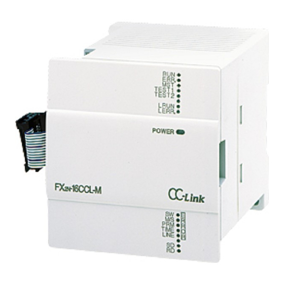
FX2N-16CCL-M CC-Link System Master Block Data Link Procedure 8 Name of Each Part and Settings This section describes the name of each part of the master block, the external dimensions the contents indicated by the LED indicators and the setting method of each switch. - Page 115 FX2N-16CCL-M CC-Link System Master Block Data Link Procedure 8 Table 8.1: Number Name Description LED indicators 1 LED status Description name Normal Error ON : Module is normal. ERR. OFF : Watchdog time error has occurred. TEST 1 Indicates the communication status with the TEST 2 stations set in parameter.
- Page 116 FX2N-16CCL-M CC-Link System Master Block Data Link Procedure 8 Number Name Description Mode setting Sets the operation status of the module. (Default setting at shipment: 0) switch Number Name Description Online Sets connection to data link. MODE ⎯ (Unusable) Offline Sets disconnection from data link.
- Page 117 FX2N-16CCL-M CC-Link System Master Block Data Link Procedure 8 Number Name Description Condition setting Sets the operation condition. (Default setting at shipment: All OFF) switch Switch status Number Setting description ⎯ ⎯ (Unusable) Always OFF ⎯ ⎯ ⎯ ⎯ (Unusable)
-
Page 118: Master Block Status Check (Hardware Test)
FX2N-16CCL-M CC-Link System Master Block Data Link Procedure 8 Master Block Status Check (Hardware Test) Check in the master block single module whether it operates normally. Make sure to execute this hardware test before constructing the system. Execute the test using the following procedure. -
Page 119: Module Wiring With Dedicated Cc-Link Cables
FX2N-16CCL-M CC-Link System Master Block Data Link Procedure 8 Module Wiring with Dedicated CC-Link Cables This section describes the connection method of dedicated CC-Link cables. • The cables can be connected without regard to the station number. • Make sure to connect a terminal resistor (offered as an accessory of the module) between the terminals DA and DB in modules at both ends. -
Page 120: T-Shaped Branch Connection Using Dedicated Cc-Link Cables
FX2N-16CCL-M CC-Link System Master Block Data Link Procedure 8 T-shaped Branch Connection Using Dedicated CC-Link Cables This section describes the T-shaped branch connection using dedicated CC-Link cables. 8.5.1 System configuration with T-shaped branch connection The figure below shows the system configuration with T-shaped branch connection. -
Page 121: T-Shaped Branch Communication Specification List
FX2N-16CCL-M CC-Link System Master Block Data Link Procedure 8 8.5.2 T-shaped branch communication specification list The table below shows the communication specification in T-shaped branch connection. For communication specification not shown in the table below, refer to Section 4.4. Table 8.2:... -
Page 122: Switch Settings
FX2N-16CCL-M CC-Link System Master Block Data Link Procedure 8 Switch Settings This section describes the setting method of each switch in the modules. 8.6.1 Station number setting (master station, remote I/O stations and remote device stations) This section describes the method to set the station number of the master station, remote I/O stations and remote device stations. - Page 123 FX2N-16CCL-M CC-Link System Master Block Data Link Procedure 8 2) Do not skip station numbers The skipped station numbers are treated as "data link faulty stations" (which can be checked in the link special register SW0080 or the buffer memory address 680 ).
-
Page 124: Mode Setting
FX2N-16CCL-M CC-Link System Master Block Data Link Procedure 8 8.6.2 Mode setting When executing the data link, the normal setting is "0(online)". 8.6.3 Transmission speed setting The available transmission speed varies depending on the total extension distance. For the details, refer to Section 4.4.1. -
Page 125: Connection Status Check (Line Test)
FX2N-16CCL-M CC-Link System Master Block Data Link Procedure 8 Connection Status Check (Line Test) After connecting all modules with dedicated CC-Link cables, execute the line test to check whether connection is correctly established to execute data link with remote stations. -
Page 126: Check Of Communication Status With Specific Remote Station (Line Test 2)
FX2N-16CCL-M CC-Link System Master Block Data Link Procedure 8 8.7.2 Check of communication status with specific remote station (line test 2) Execute the line test 2 to check whether data link is normally executed with a specific remote station. There is no need to set parameters. -
Page 127: Parameter Check (Parameter Verification Test)
FX2N-16CCL-M CC-Link System Master Block Data Link Procedure 8 Parameter Check (Parameter Verification Test) The contents of the parameters can be verified. Execute the test using the following procedure. Start Set the mode setting switch in the master block to 5. - Page 128 FX2N-16CCL-M CC-Link System Master Block Data Link Procedure 8 Continued from the previous page The test result is indicated by the LED indicators in the master module. By changing over the setting of the mode setting switch, the contents of the parameter corresponding to each mode number are indicated by the LED indicators.
-
Page 129: Programming
FX2N-16CCL-M CC-Link System Master Block Programming 9 Programming Precautions in Programming This section describes precautions in creating a program. 1) Word information of the remote device station is processed in FX -16CCL-M in one word unit. Therefore, trying to transfer double word (32-bit data) between FX... - Page 130 FX2N-16CCL-M CC-Link System Master Block Programming 9 4) Create such a program that detects the data link status in remote I/O stations and remote device stations and executes interlock. Create a program for error handling. SW0080(Data link status in other stations)
-
Page 131: Programming Procedure
FX2N-16CCL-M CC-Link System Master Block Programming 9 Programming Procedure This section describes the program creation procedure. 9.2.1 Communication between master station and remote I/O stations The flowchart below shows the basic programming procedure for communication between the master station and remote I/O stations. -
Page 132: Communication Between Master Station And Remote Device Stations
FX2N-16CCL-M CC-Link System Master Block Programming 9 9.2.2 Communication between master station and remote device stations The flowchart below shows the basic programming procedure for communication between the master station and remote device stations. For a program example, refer to Chapter 11. -
Page 133: Communication In Compound System
FX2N-16CCL-M CC-Link System Master Block Programming 9 9.2.3 Communication in compound system The basic programming procedure for the system where both remote I/O stations and remote device stations are present is equivalent to that described in "9.2.2 Communication between master station and remote device stations". -
Page 134: Link Special Relay/Register (Sb/Sw)
FX2N-16CCL-M CC-Link System Master Block Programming 9 Link Special Relay/Register (SB/SW) The data link status can be checked using the bit information (link special relay SB) and the word information (link special register SW). "SB" and "SW" represent the buffer memory information in the master block, and can be read and written by the FROM/TO instruction. - Page 135 FX2N-16CCL-M CC-Link System Master Block Programming 9 Buffer memory Number Name Description Number Indicates the data link restart specification Data link restart acceptance status. SB0040 acceptance status OFF : Not accepted ON : Accepted Indicates the data link restart specification Data link restart acceptance completion status.
- Page 136 FX2N-16CCL-M CC-Link System Master Block Programming 9 Buffer memory Number Name Description Number Indicates the offline test execution status. Offline test SB0050 OFF : Not executed execution status ON : Being executed Indicates the setting status of the mode setting switch in the module.
- Page 137 FX2N-16CCL-M CC-Link System Master Block Programming 9 Buffer memory Number Name Description Number Indicates the error invalid station specification status Error invalid station by parameter (SW0078). SB0075 specification status OFF : Not specified ON : Specified Indicates the temporary error invalid station Temporary error specification status (SW007C).
-
Page 138: Link Special Register (Sw)
FX2N-16CCL-M CC-Link System Master Block Programming 9 9.3.2 Link special register (SW) Table 9.2: Buffer Number Name Description memory Selects whether or not to specify two or more temporary error invalid stations. Specification of 00: Specifies two or more stations stored in SW0004. - Page 139 FX2N-16CCL-M CC-Link System Master Block Programming 9 Buffer Number Name Description memory Indicates the execution result of request for parameter Result of request for verification test by SB0009. SW004F parameter 0 : Normal: verification test Other than 0 : Error code Stores the setting status of the mode setting switch.
- Page 140 FX2N-16CCL-M CC-Link System Master Block Programming 9 Buffer Number Name Description memory Current link scan SW006E Stores the current value of the link scan time (unit: 1 ms). time Minimum link scan SW006F Stores the minimum value of the link scan time (unit: 1 ms).
- Page 141 FX2N-16CCL-M CC-Link System Master Block Programming 9 Buffer Number Name Description memory Stores the data link status in each station. 0: Normal 1: Data link error Data link status in SW0080 b15 b14 b13 b12 other stations SW0080 ⎯ Numbers 1 to 15 above indicate station numbers Stores the watchdog timer error occurrence status in each station.
- Page 142 FX2N-16CCL-M CC-Link System Master Block Programming 9 Buffer Number Name Description memory Stores the overlap status in which the head station number of each module does not overlap. 0: Normal 1: Station number overlap (only the head station number) Station number...
- Page 143 FX2N-16CCL-M CC-Link System Master Block Programming 9 Buffer Number Name Description memory Stores the line test 2 result. SW00B8 Line test 2 result 0 : Normal Other than 0 : Error code (Refer to Section 13.3.) Stores the status of parameter registration to the EEPROM EEPROM.
- Page 144 FX2N-16CCL-M CC-Link System Master Block Programming 9 MEMO 9-16...
-
Page 145: Communication Between Master Station And Remote I/O Stations
FX2N-16CCL-M CC-Link System Master Block Communication between Master Station and Remote I/O Stations 10 Communication between Master Station and Remote I/O Stations This chapter describes module setting, programming and operation check using a system configuration example. 10.1 System Configuration It is supposed that three remote I/O stations are connected in the system. -
Page 146: Setting Of Remote I/O Station
FX2N-16CCL-M CC-Link System Master Block Communication between Master Station and Remote I/O Stations 10 10.1.2 Setting of remote I/O station The figure below shows the setting of the switches in a remote I/O station. Transmission speed setting switch Station number setting switch. -
Page 147: Creating A Program
FX2N-16CCL-M CC-Link System Master Block Communication between Master Station and Remote I/O Stations 10 10.2 Creating a Program 10.2.1 Program for parameters In the program below, data link automatically starts when the PLC starts to run. [Caution] The auxiliary relays in the non-keep area must be used as auxiliary relays (M) for parameter setting programs. - Page 148 FX2N-16CCL-M CC-Link System Master Block Communication between Master Station and Remote I/O Stations 10 M8002 Refresh command Initial pulse Module Module error ready When data link startup by buffer memory parameters is completed normally FROM H0668 D100 When data link...
-
Page 149: Program For Communication
FX2N-16CCL-M CC-Link System Master Block Communication between Master Station and Remote I/O Stations 10 10.2.2 Program for communication The figure below shows a program to control remote I/O stations. It is supposed that the relationship among the PLC, the master station buffer memory and the remote I/O stations is as shown below. - Page 150 FX2N-16CCL-M CC-Link System Master Block Communication between Master Station and Remote I/O Stations 10 [Program to control remote I/O stations] M500 Data link is being executed in the Module Module Data link status in master station. error ready host station...
-
Page 151: Execution Of Data Link
FX2N-16CCL-M CC-Link System Master Block Communication between Master Station and Remote I/O Stations 10 10.3 Execution of Data Link Turn on the power of the remote I/O stations first, turn on the power of the master station, then start the data link. -
Page 152: Confirmation Of Operation By Program
FX2N-16CCL-M CC-Link System Master Block Communication between Master Station and Remote I/O Stations 10 10.3.2 Confirmation of operation by program Using a sequence program, make sure that data link is normally proceeding. ➀ For example, when the input X00 in the remote I/O station AJ65BTB1-16D (station No. 1) is set to ON, the output Y000 in the master station turns ON. -
Page 153: Communication Between Master Station And Remote Device Stations
FX2N-16CCL-M CC-Link System Master Block Communication between Master Station and Remote Device Stations 11 Communication between Master Station and Remote Device Stations This chapter describes module setting, programming and operation check using a system configuration example. 11.1 System Configuration It is supposed that two remote device stations are connected in the system. -
Page 154: Setting Of Remote Device Station
FX2N-16CCL-M CC-Link System Master Block Communication between Master Station and Remote Device Stations 11 11.1.2 Setting of remote device station The figure below shows the setting of the switches in a remote device station. Transmission speed setting switch Station number setting switch. -
Page 155: Creating A Program
FX2N-16CCL-M CC-Link System Master Block Communication between Master Station and Remote Device Stations 11 11.2 Creating a Program 11.2.1 Program for parameters In the program below, data link automatically starts when the PLC starts to run. [Caution] The auxiliary relays in the non-keep area must be used as auxiliary relays (M) for parameter setting programs. - Page 156 FX2N-16CCL-M CC-Link System Master Block Communication between Master Station and Remote Device Stations 11 M8002 Refresh command Initial pulse Module Module error ready When data link startup by buffer memory parameters is completed normally FROM H0668 D100 When data link...
-
Page 157: Program For Communication
FX2N-16CCL-M CC-Link System Master Block Communication between Master Station and Remote Device Stations 11 11.2.2 Program for communication The figure below shows a program to control remote device stations. It is supposed that the relationship among the PLC, the master station buffer memory and the remote device stations is as shown below. - Page 158 FX2N-16CCL-M CC-Link System Master Block Communication between Master Station and Remote Device Stations 11 [Remote register (RWw, RWr)] Remote device station (station No. 1) AJ65BT-64AD Master station Address Remote register (RWw) Remote register (RWw) Averaging processing Averaging processing D100 specification...
- Page 159 FX2N-16CCL-M CC-Link System Master Block Communication between Master Station and Remote Device Stations 11 [Program to control remote device stations] Reads the data link status in FROM H0680 K4M501 remote device station (SW0080). Module Module Data link status in error...
- Page 160 FX2N-16CCL-M CC-Link System Master Block Communication between Master Station and Remote Device Stations 11 (CH1 A/D conversion completion flag: RX0) Remote ready M127 M100 (RX1B) FROM H02E0 D200 CH1 digital output value Reads digital (CH2 A/D conversion completion flag: RX1) M101 values.
-
Page 161: Execution Of Data Link
FX2N-16CCL-M CC-Link System Master Block Communication between Master Station and Remote Device Stations 11 11.3 Execution of Data Link Turn on the power of the remote device stations first, turn on the power of the master station, then start the data link. -
Page 162: Confirmation Of Operation By Program
FX2N-16CCL-M CC-Link System Master Block Communication between Master Station and Remote Device Stations 11 11.3.2 Confirmation of operation by program Using a sequence program, make sure that data link is proceeding normally. ➀ The digital values converted by the AJ65BT-64AD are stored in D200 (CH1 digital value) and D201 (CH2 digital value). -
Page 163: Communication In Compound System
FX2N-16CCL-M CC-Link System Master Block Communication in Compound System 12 Communication in Compound System This chapter describes module setting, programming and operation confirmation in the system in which remote I/O station and remote device station exist together using a system configuration example. -
Page 164: Setting Of Remote I/O Station
FX2N-16CCL-M CC-Link System Master Block Communication in Compound System 12 12.1.2 Setting of remote I/O station The figure below shows the setting of the switches in the remote I/O station. Transmission speed setting switch Station number setting switch. 0 (×10) 2 (2.5Mbps) -
Page 165: Creating A Program
FX2N-16CCL-M CC-Link System Master Block Communication in Compound System 12 12.2 Creating a Program 12.2.1 Program for parameters In the program below, data link automatically starts when the PLC starts to run. [Caution] The auxiliary relays in the non-keep area must be used as auxiliary relays (M) for parameter setting programs. - Page 166 FX2N-16CCL-M CC-Link System Master Block Communication in Compound System 12 M8002 Refresh command Initial pulse Module Module error ready When data link startup by buffer memory parameters is completed normally FROM H0668 D100 When data link startup by buffer memory parameters...
-
Page 167: Program For Communication
FX2N-16CCL-M CC-Link System Master Block Communication in Compound System 12 12.2.2 Program for communication The figure below shows a program to control the remote I/O station and the remote device station. It is supposed that the relationship among the PLC, the master station buffer memory, the remote I/O station and the remote device station is as shown below. - Page 168 FX2N-16CCL-M CC-Link System Master Block Communication in Compound System 12 [Remote register (RWw, RWr) Master station Address Remote register (RWw) D100 RWw 0 Remote device station (station No. 2) D101 RWw 1 For station -32CCL No. 1 D102 RWw 2...
- Page 169 FX2N-16CCL-M CC-Link System Master Block Communication in Compound System 12 [Program to control remote I/O stations and remote device stations] Reads the data link status in remote FROM H0680 K4M501 station (SW0080). Module Module Data link error ready status in...
-
Page 170: Execution Of Data Link
FX2N-16CCL-M CC-Link System Master Block Communication in Compound System 12 12.3 Execution of Data Link Turn on the power of the modules in the order "remote I/O station, remote device station → master station", then start the data link. 12.3.1... -
Page 171: Confirmation Of Operation By Program
FX2N-16CCL-M CC-Link System Master Block Communication in Compound System 12 3) LED indication in the remote device station Make sure that the LED indication status is as shown below. 5V DC is supplied from the PLC. Data link is normally proceeding. - Page 172 FX2N-16CCL-M CC-Link System Master Block Communication in Compound System 12 MEMO 12-10...
-
Page 173: Troubleshooting
FX2N-16CCL-M CC-Link System Master Block Troubleshooting 13 Troubleshooting STARTING AND MAINTENANCE PRECAUTIONS • Do not touch the terminals while the power is supplied. Otherwise, electrical shock or malfunction may be caused. • Turn off the power first, then clean the module or tightening the screws. -
Page 174: Verification When Trouble Occurs
FX2N-16CCL-M CC-Link System Master Block Troubleshooting 13 13.1 Verification when Trouble Occurs The table below shows the details to be checked and corrective actions for each trouble occurrence. Table 13.1: Trouble description Details to be checked Confirmation method Check the cable status visually or by the line Are any cables broken? test. - Page 175 FX2N-16CCL-M CC-Link System Master Block Troubleshooting 13 Trouble description Details to be checked Confirmation method Check the following: Is the remote device station executing data • LED indication in the module link? • Communication status in the master station with other stations (SW0080)
- Page 176 FX2N-16CCL-M CC-Link System Master Block Troubleshooting 13 Trouble description Details to be checked Confirmation method Is the data link stop (SB0002) ON? Confirm the sequence program. Data link cannot Check the data link stop result be stopped. Has an error occurred? (SW0045).
-
Page 177: Troubleshooting When Err Led Is Flashing In Master Station
FX2N-16CCL-M CC-Link System Master Block Troubleshooting 13 13.2 Troubleshooting when ERR LED is Flashing in Master Station ERR LED is flashing in master station. Is parameter setting consistent with loading system configuration? Correct parameter setting or loading system configuration. Is link special... - Page 178 FX2N-16CCL-M CC-Link System Master Block Troubleshooting 13 From the From the From the previous page previous page previous page Is L RUN LED lit? Is SD LED lit (flashing)? Is transmission speed correctly set? Is SD LED lit (flashing)? Set transmission speed correctly.
-
Page 179: Error Codes
FX2N-16CCL-M CC-Link System Master Block Troubleshooting 13 13.3 Error Codes The table below shows the error codes stored in the link special register (SW). Table 13.2: Error code Description Cause of error (details) Corrective action (hex.) Message receive B110 A line error has occurred. - Page 180 FX2N-16CCL-M CC-Link System Master Block Troubleshooting 13 Table 13.2: Error code Description Cause of error (details) Corrective action (hex.) Loading/ The station type is different between B30A parameter Set the parameter correctly. the module and the parameter. consistency error Loading/...
- Page 181 FX2N-16CCL-M CC-Link System Master Block Troubleshooting 13 Error code Description Cause of error (details) Corrective action (hex.) Number of retries The number of retries (address 2 Set a value inside the range from 1 to B391 setting error (parameter) is not set inside the (parameter) range from 1 to 7.
- Page 182 FX2N-16CCL-M CC-Link System Master Block Troubleshooting 13 Error code Description Cause of error (details) Corrective action (hex.) When the write request for parameter registration to EEPROM (BFM#A b10) was executed, the EEPROM B901 EEPROM error Replace the module. was defective or the specified number of times of write (10,000 times) is exceeded.
-
Page 183: Led Indication Status
FX2N-16CCL-M CC-Link System Master Block Troubleshooting 13 13.4 LED Indication Status This section shows the LED indication status in each station in each data link (system) status. Use this section as reference of troubleshooting. 13.4.1 When data link is normal The RUN, MST, L RUN, SD and RD LED indicators are ON. -
Page 184: When A Cable Is Short-Circuited
FX2N-16CCL-M CC-Link System Master Block Troubleshooting 13 13.4.3 When a cable is short-circuited Data link is disabled in all stations. The L RUN LED indicator is OFF in all stations except the master station. However, the short- circuited point cannot be detected from the LED indication. -
Page 185: When Power Supply To A Remote I/O Station Is Turned Off
FX2N-16CCL-M CC-Link System Master Block Troubleshooting 13 13.4.5 When power supply to a remote I/O station is turned off Data link continues excluding the remote I/O station. The ERR LED indicator is flashing in the master station. ★ ERR. Because data link is... -
Page 186: When A Station Number Overlaps
FX2N-16CCL-M CC-Link System Master Block Troubleshooting 13 13.4.7 When a station number overlaps The example below shows a case in which a station number overlaps in a remote I/O station and a remote device station. Because a skipped number (number without a slave station) is made in the system due to station number overlap, the ERR LED indicator is flashing in the master station. -
Page 187: When The Switch Setting Is Changed During Data Link
FX2N-16CCL-M CC-Link System Master Block Troubleshooting 13 13.4.9 When the switch setting is changed during data link The example below shows a case in which the switch setting is changed in a remote I/O station. The L ERR LED indicator is flashing in a remote I/O station in which the switch setting is changed. -
Page 188: 11When A Remote I/O Station Is Not Set In The Parameter (And Set As A Reserved Station)
FX2N-16CCL-M CC-Link System Master Block Troubleshooting 13 13.4.11 When a remote I/O station is not set in the parameter (and set as a reserved station) Data link is completely disabled in the remote I/O station, and no error occurs. The L RUN and SD LED indicators are OFF in the remote I/O station. -
Page 189: Appendix
FX2N-16CCL-M CC-Link System Master Block Appendix 14 Appendix Parameter setting sheet Table 14.1: Buffer Preset Item Setting range memory Remarks Default value address Number of ⎯ 1 to 15 connected modules ⎯ Number of retries 1 to 7 Number of automatic ⎯... - Page 190 FX2N-16CCL-M CC-Link System Master Block Appendix 14 Station information setting sheet Table 14.2: Station Number of Reserved station/invalid station Station type number occupied stations specification 14-2...
- Page 191 FX2N-16CCL-M CC-Link System Master Block Appendix 14 Device assignment sheet (remote I/O) Table 14.3: Station Remote input (RX) Remote output (RY) number RX00 to RX1F → RY00 to RY1F → RX20 to RX3F → RY20 to RY3F → RX40 to RX5F →...
- Page 192 FX2N-16CCL-M CC-Link System Master Block Appendix 14 MEMO 14-4...
- Page 194 Fax: +371 (0)784 / 2281 MITSUBISHI ELECTRIC Mitsubishi Electric Europe B.V. /// FA - European Business Group /// Gothaer Straße 8 /// D-40880 Ratingen /// Germany Tel.: +49(0)2102-4860 /// Fax: +49(0)2102-4861120 /// info@mitsubishi-automation.com /// www.mitsubishi-automation.com FACTORY AUTOMATION Specifications subject to change /// 01.2008...
Need help?
Do you have a question about the FX2N-16CCL-M and is the answer not in the manual?
Questions and answers