Mitsubishi FX2N Hardware Manual
16ccl-m cc-link system master block
Hide thumbs
Also See for FX2N:
- Hardware manual (127 pages) ,
- User manual (70 pages) ,
- Programming manual (466 pages)
Table of Contents
Advertisement
Quick Links
This manual contains text, diagrams and explanations which will guide the reader in the correct installation
and operation of the FX
understood before attempting to install or use the unit. Further information can be found in the FX series
PLC hardware manuals.
Guidelines for the safety of the user and protection of the FX
SYSTEM MASTER BLOCK
•
If in doubt at any stage during the installation of the FX
BLOCK always consult a professional electrical engineer who is qualified and trained to the local
and national standards. If in doubt about the operation or use of the FX
SYSTEM MASTER BLOCK please consult the nearest Mitsubishi Electric distributor.
•
Under no circumstances will Mitsubishi Electric be liable or responsible for any consequential
damage that may arise as a result of the installation or use of this equipment.
•
All examples and diagrams shown in this manual are intended only as an aid to
understanding the text, not to guarantee operation. Mitsubishi Electric will accept no
responsibility for actual use of the product based on these illustrative examples.
•
Owing to the very great variety in possible application of this equipment, you must satisfy
yourself as to its suitability for your specific application.
Note's on the symbology used in this manual
At various times through out this manual certain symbols will be used to highlight points of information
which are intended to ensure the user's personal safety and protect the integrity of the equipment.
Whenever any of the following symbols are encountered, its associated note must be read and
understood. Each of the symbols used will now be listed with a brief description of its meaning.
Hardware warnings
1) Indicates that the identified danger WILL cause physical and property damage.
2) Indicates that the identified danger could POSSIBLY cause physical and property damage.
1. INTRODUCTION
1.1 Associated Manuals
Manual name
#FX
-16CCL-M
2N
User's Manual
#FX
/FX
/FX
/FX
1S
1N
2N
Programming Manual II
✩FX
Hardware Manual
1N
✩FX
Hardware Manual
2N
✩FX
Hardware Manual
2NC
✩FX
-32CCL
2N
User's Manual
#: Indispensable manual
✩: Manual required depending on equipment used
FX
-16CCL-M CC-Link SYSTEM MASTER BLOCK. It should be read and
2N
Manual number
JY992D93101
(sent separately)
JY992D88101
2NC
(sent separately)
JY992D89301
(packed with product)
JY992D66301
(packed with product)
JY992D76401
(packed with product)
JY992D71801
(packed with product)
-16CCL-M CC-Link SYSTEM MASTER BLOCK
2N
HARDWARE MANUAL
-16CCL-M CC-Link SYSTEM MASTER
2N
Describes programming and handling of the CC-
Link master block FX
Explains the instructions in the FX
FX
Series PLC.
2NC
Describes the contents related to the hardware
such as specification, wiring and mounting of the
FX
Series PLC.
1N
Describes the contents related to the hardware
such as specification, wiring and mounting of the
FX
Series PLC.
2N
Describes the contents related to the hardware
such as specification, wiring and mounting of the
FX
Series PLC.
2NC
Describes programming and handling of the CC-
Link interface block FX
JY992D93201B
-16CCL-M CC-Link
2N
-16CCL-M CC-Link
2N
Description
-16CCL-M.
2N
1S
-32CCL.
2N
CC-Link Ver.1.10
/FX
/FX
/
1N
2N
Advertisement
Table of Contents

Related Manuals for Mitsubishi FX2N


Summary of Contents for Mitsubishi FX2N
- Page 1 SYSTEM MASTER BLOCK please consult the nearest Mitsubishi Electric distributor. • Under no circumstances will Mitsubishi Electric be liable or responsible for any consequential damage that may arise as a result of the installation or use of this equipment. •...
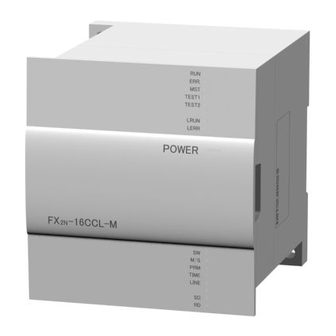
- Page 2 1.2 Overview The CC-Link master block FX -16CCL-M is a special extension block which assigns an FX Series PLC as the master station of the CC-Link system. 1) Remote I/O stations and remote device stations can be connected to the master station (FX Series PLC).
- Page 3 Number Name Description ON : Switch setting error has occurred. indicators 2 ON : The master station is already present in the same line. PRM ON : Parameter setting error has occurred. ON : Data link watchdog timer is actuated TIME TIME (error in all stations).
- Page 4 2. Installation and wiring INSTALLATION PRECAUTIONS • Use the module in the environment described in the USER’S MANUAL General Specification. Do not use the PLC in a place with dust, soot, conductive dust, corrosive gas or combustible gas, place exposed to high temperature, condensation, wind or rain or place with vibration or impact.
- Page 5 2.3 Module Wiring with Dedicated CC-Link Cables This section describes the connection method of dedicated CC-Link cables. • The cables can be connected without regard to the station number. • Make sure to connect a terminal resistor (offered as an accessory of the module) between the terminals DA and DB in modules at both ends.
- Page 6 -CNV-IF is required. Manual number : JY992D93201 Manual revision : B Date : MAR. 2003 HEAD OFFICE : MITSUBISHI DENKI BLDG MARUNOUTI TOKYO 100-8310 HIMEJI WORKS : 840, CHIYODA CHO, HIMEJI, JAPAN Effective MAR. 2003 JY992D93201B Specifications are subject to...
- Page 7 Remote device station Online Sets connection to data link. • Under no circumstances will Mitsubishi Electric be liable or responsible for any consequential (Unusable) damage that may arise as a result of the installation or use of this equipment.
- Page 8 Remote device station : Remote I/O = 32/32 (RX/RY) points Number of link points Remote register = 4 (RWw) points HEAD OFFICE : MITSUBISHI DENKI BLDG MARUNOUTI TOKYO 100-8310 HIMEJI WORKS : 840, CHIYODA CHO, HIMEJI, JAPAN (master station → remote device station)
Need help?
Do you have a question about the FX2N and is the answer not in the manual?
Questions and answers