Table of Contents
Advertisement
Quick Links
Advertisement
Table of Contents

Related Manuals for Mitsubishi FX2N-16LNK-M


Summary of Contents for Mitsubishi FX2N-16LNK-M
- Page 1 USER’S MANUAL -16LNK-M MELSEC-I/O LINK REMOTE I/O SYSTEM MASTER BLOCK...
- Page 2 -16LNK-M MELSEC-I/O LINK REMOTE I/O SYSTEM • If in doubt about the operation or use of MASTER BLOCK please consult the nearest Mitsubishi Electric distributor. • This manual is subject to change without notice.
- Page 3 -16LNK-M MELSEC-I/O LINK REMOTE I/O SYSTEM MASTER BLOCK -16LNK-M MELSEC-I/O LINK REMOTE I/O SYSTEM MASTER BLOCK Manual number : JY992D73701 USER’S MANUAL Manual revision : Date October 2004...
- Page 4 -16LNK-M MELSEC-I/O LINK REMOTE I/O SYSTEM MASTER BLOCK Guidelines for the safety of the user and protection of the FX -16LNK-M MELSEC-I/O LINK SYSTEM MASTER BLOCK This manual provides information for the installation and use of the FX -16LNK-M MELSEC-I/O LINK SYSTEM MASTER BLOCK.
- Page 5 -16LNK-M MELSEC-I/O LINK REMOTE I/O SYSTEM MASTER BLOCK Hardware warnings 1 ) Indicates that the identified danger WILL cause physical and property damage. 2 ) Indicates that the identified danger POSSIBLY cause physical and property damage. 3 ) Indicates a point of further interest or further explanation. Software warnings 1 ) Indicates special care must be taken when using this element of software.
- Page 6 • All examples and diagrams shown in this manual are intended only as an aid to understanding the text, not to guarantee operation. Mitsubishi Electric will accept no responsibility for actual use of the product based on these illustrative examples.
-
Page 7: Table Of Contents
-16LNK-M MELSEC-I/O LINK REMOTE I/O SYSTEM MASTER BLOCK Contents CONTENTS 1. Notes to User .....................1-1 1.1 Outline of product ...................... 1-1 1.2 Manual configuration and diversified data ..............1-2 2. Product Specifications ................2-1 2.1 System configuration ....................2-1 2.2 Appearance and name of each portion ..............2-3 2.3 General specifications and performance specifications .......... - Page 8 -16LNK-M MELSEC-I/O LINK REMOTE I/O SYSTEM MASTER BLOCK Contents MEMO...
-
Page 9: Notes To User
-16LNK-M MELSEC-I/O LINK REMOTE I/O SYSTEM MASTER BLOCK Notes to user 1 Notes to User Outline of product The MELSEC-I/O LINK REMOTE I/O SYSTEM MASTER BLOCK FX -16LNK-M (hereinafter referred to as "master block") is connected to an FX Series programmable controller (PC), and realizes a remote I/O system which saves wiring and enables easy programming for communication with remote I/O units. -
Page 10: Manual Configuration And Diversified Data
-16LNK-M MELSEC-I/O LINK REMOTE I/O SYSTEM MASTER BLOCK Notes to user 1 Manual configuration and diversified data This user manual exclusively is packed together with the master block. For programs in a basic PC unit, handling of remote I/O units, etc., refer to the corresponding data. User manual (this manual) This manual describes cautions on safety, specifications, attachment and wiring of the master block, program- ming and troubleshooting. -
Page 11: Product Specifications
-16LNK-M MELSEC-I/O LINK REMOTE I/O SYSTEM MASTER BLOCK Product Specifications 2 Product Specifications System configuration Example of system configuration • Basic unit • I/O link master block FX Series -16LNK-M -CNV-IF is required when FX *1:Extension unit, extension block, special extension unit or is connected. - Page 12 -16LNK-M MELSEC-I/O LINK REMOTE I/O SYSTEM MASTER BLOCK Product Specifications 2 Number of connected master blocks The number of connected master blocks can be arbitrary as far as the total number of I/O points of a basic unit, master blocks, extension units/blocks and special extension units/blocks (occupying eight input or output points) satisfies the following.
-
Page 13: Appearance And Name Of Each Portion
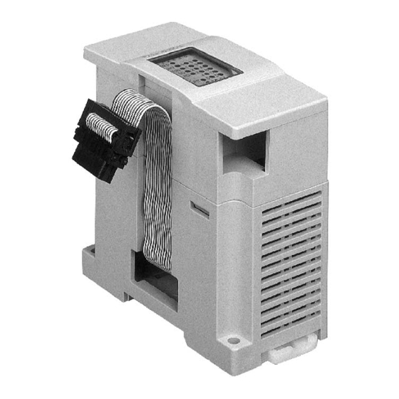
-16LNK-M MELSEC-I/O LINK REMOTE I/O SYSTEM MASTER BLOCK Product Specifications 2 Appearance and name of each portion Face painting color: Munsell 0.08GY/7.64/0.81 Weight: 0.5 kg External 24 VDC Terminal screw M3 ground terminal On-line station POWER LED setting switch 8 9 A B C D E F POWER POWER Error... -
Page 14: General Specifications And Performance Specifications
-16LNK-M MELSEC-I/O LINK REMOTE I/O SYSTEM MASTER BLOCK Product Specifications 2 General specifications and performance specifications General specifications Specifications item Description During operation 0 to 55°C (32 to 131°F) Ambient temperature During storage -20 to 70°C (-4 to 158°F) Ambient During operation 35 to 85%RH (no condensation) humidity EN68-2-6 :10 - 57 Hz, 0.075mm Half Amplitude. - Page 15 -16LNK-M MELSEC-I/O LINK REMOTE I/O SYSTEM MASTER BLOCK Product Specifications 2 Performance specifications Specifications item Description Maximum number of con- 128 points (16 remote units with 4 points each) per master block trolled I/O points I/O refresh time Approx. 5.4 ms (without regard to number of I/O points) Communication speed 38400 bps Communication method...
- Page 16 -16LNK-M MELSEC-I/O LINK REMOTE I/O SYSTEM MASTER BLOCK Product Specifications 2 Cable specifications Specifications item Description Cable type Shielded twisted-pair cable Cabtyre cable * × 1P × 2C Logarithm 0.75 mm 0.75 mm Conductive resistance (20° ° ° ° C) 29 Ω/km or less ...
- Page 17 -16LNK-M MELSEC-I/O LINK REMOTE I/O SYSTEM MASTER BLOCK Product Specifications 2 • Recommended cables The table below shows the model names, the specifications and the manufacturer of recommended cables. Recommended cables Item Specifications Model name KNPEV-SB 0.75SQ×1P KNEV 0.75SQ×2C Cable type Shielded twisted-pair cable Unshielded cabtyre cable ×...
- Page 18 -16LNK-M MELSEC-I/O LINK REMOTE I/O SYSTEM MASTER BLOCK Product Specifications 2 Model name Type SPEV(SB)-0.75-1P Shielded twisted-pair cable (1 P) KMPEV-SB CWS-178 0.75SQ×1P Shielded twisted-pair cable (1 P) 2PNCT 0.75SQ×2C Two-cored cabtyre cable DPEV SB 0.75×1P Shielded twisted-pair cable (1 P) VCT 0.75×2C Two-cored cabtyre cable D-KPEV-SB 0.75×1P...
-
Page 19: Connection And Wiring
-16LNK-M MELSEC-I/O LINK REMOTE I/O SYSTEM MASTER BLOCK Connection and Wiring 3 Connection and Wiring Cautions on connection Cautions on design • Construct interlock circuits on a sequence program so that the system operates conservatively when a communication error has occurred in a data link. If the system does not operate conservatively, an accident may be caused by erroneous outputs and/or malfunction. - Page 20 -16LNK-M MELSEC-I/O LINK REMOTE I/O SYSTEM MASTER BLOCK Connection and Wiring 3 Cautions on system configuration Pay attention to the following points in the power supply wiring (system design) so that erroneous inputs to or outputs from remote I/O units can be prevented. 1 ) Countermeasures against erroneous inputs or outputs occurred when the power is turned on or off •...
- Page 21 -16LNK-M MELSEC-I/O LINK REMOTE I/O SYSTEM MASTER BLOCK Connection and Wiring 3 ➀ 24V DC supplied from outside (for I/O unit power and input power supplied from outside) 5 V DC inside Input (Xn) When the input power supplied from the outside is turned off, the input Xn is turned off after the response time of input unit ON →...
- Page 22 -16LNK-M MELSEC-I/O LINK REMOTE I/O SYSTEM MASTER BLOCK Connection and Wiring 3 Countermeasures against erroneous inputs or outputs Perform wiring of a PC unit and a stabilized power supply unit from a same power supply. • When the 24V DC service power supply of a PC unit is used Series AC power supply type 24+ 24- 24+ 24-...
- Page 23 -16LNK-M MELSEC-I/O LINK REMOTE I/O SYSTEM MASTER BLOCK Connection and Wiring 3 Series DC power supply type 24+ 24- 24+ 24- 24+ 24- Basic or extension unit Master block Remote I/O unit Series (DC power supply type) When an FX Series PC is combined and used in an environment with much noises, provide a noise filter between a DC power supply and the FX PC.
- Page 24 -16LNK-M MELSEC-I/O LINK REMOTE I/O SYSTEM MASTER BLOCK Connection and Wiring 3 Grounding • When grounding the FG terminal, use a wire as thick as possible (2.0 mm Perform grounding as shown below. Never perform common grounding with equipment with high fre- quency.
-
Page 25: Connection Method
-16LNK-M MELSEC-I/O LINK REMOTE I/O SYSTEM MASTER BLOCK Connection and Wiring 3 Connection method The figures below show the connection diagrams with twisted-pair cables and cabtyre cables respectively. Connection with twisted-pair cables Remote I/O unit ➀ Remote I/O unit ➁ Remote I/O unit ➂... - Page 26 -16LNK-M MELSEC-I/O LINK REMOTE I/O SYSTEM MASTER BLOCK Connection and Wiring 3 Reference When two or more units are supplied from one power supply unit, make sure that the voltage required by each unit is satisfied. Remote I/O unit ➀ Remote I/O unit ➁...
-
Page 27: Operation
-16LNK-M MELSEC-I/O LINK REMOTE I/O SYSTEM MASTER BLOCK Operation 4 Operation Operating procedure The flowchart below shows the operating procedure. Start Set the on-line station setting switch and the I/O occupation setting switch on the front ..Refer to 4.2 face of a master block. -
Page 28: Setting And Function Of Each Portion
-16LNK-M MELSEC-I/O LINK REMOTE I/O SYSTEM MASTER BLOCK Operation 4 Setting and function of each portion The table below shows the setting contents and the function of each setting switch provided on a master block. For layout of the each setting switch, refer to Paragraph 2.2. Setting switches Name Description... - Page 29 -16LNK-M MELSEC-I/O LINK REMOTE I/O SYSTEM MASTER BLOCK Operation 4 Name Description Set the station Nos. of connected remote I/O units. "0" to "F" indicate station On-line station setting Nos. switch ON: To be communicated (with error check) OFF: Not to be communicated (without error check) 0 1 2 3 4 5 6 7 * Station Nos.
- Page 30 -16LNK-M MELSEC-I/O LINK REMOTE I/O SYSTEM MASTER BLOCK Operation 4 LED indication and terminal block Name Status Description Supply voltage of power (24V DC) supplied from out- side is normal. 24 V POWER Extin- Supply voltage of power (24V DC) supplied from out- guished side is insufficient.
- Page 31 -16LNK-M MELSEC-I/O LINK REMOTE I/O SYSTEM MASTER BLOCK Operation 4 Name Status Description Terminal block Connects signals, power supplies and RUN outputs (size: M3, tightening torque: 100 to 135 N cm). Name Description DATA Data Data ground Ground +24V DC power supply for transmission (plus side) -24V DC power supply for transmission (minus side) External output for lighting (or extinguished) status of RUN LED RUNA...
- Page 32 -16LNK-M MELSEC-I/O LINK REMOTE I/O SYSTEM MASTER BLOCK Operation 4 Terminals RUNA and RUNB Indicator lamps can be attached outside a terminal block by utilizing these terminals so that it can be checked wither or not the I/O link system is correctly operating. Rated current Load voltage 250V AC, 30V DC (External commutating diode is required.)
-
Page 33: Setting Of Station No
-16LNK-M MELSEC-I/O LINK REMOTE I/O SYSTEM MASTER BLOCK Operation 4 Setting of station No. This paragraph describes how to set the station No. of an remote I/O unit. Remote I/O unit station No. setting (ST.NO.) switch • Set the station No. within the range of 0 to F. Station Nos. -
Page 34: Program
-16LNK-M MELSEC-I/O LINK REMOTE I/O SYSTEM MASTER BLOCK Operation 4 Program Set the station Nos., set the mode and perform wiring in accordance with "4.1 Operating procedure". Set the station Nos. and the mode using the following procedure. Standard mode 1 ) Set the I/O occupation setting switch MOD2 to ON (initial value). - Page 35 -16LNK-M MELSEC-I/O LINK REMOTE I/O SYSTEM MASTER BLOCK Operation 4 4 ) Assign remote I/O units to be used to the table above from the station No. 0 in turn. Example Master block FX -16LNK-M Arbitrary number can be assigned as a 8 I/O points (4 for input 4 input points 8 output points...
- Page 36 -16LNK-M MELSEC-I/O LINK REMOTE I/O SYSTEM MASTER BLOCK Operation 4 5 ) Assign actual I/O Nos. to the assignment table shown on the previous page. Assign I/O No. to each remote I/O unit from the I/O No. in the position in which a master block FX 16LNK-M is connected.
- Page 37 -16LNK-M MELSEC-I/O LINK REMOTE I/O SYSTEM MASTER BLOCK Operation 4 [ Hint ] • When the available first input No. is not equivalent to the available first output No. in the position in which a master block is connected In the example on the previous page, the available first input No. (X050) is equivalent to the available first output No.
- Page 38 -16LNK-M MELSEC-I/O LINK REMOTE I/O SYSTEM MASTER BLOCK Operation 4 [ Example of I/O assignment in standard mode ] X000 to X007 X010 to Y010 to X020 to X117 X020 to X023 X064 to X067 Y000 to Y007 Y017 Y017 Y020 to Y117 Y050 to Y057 Y020 to Y023...
- Page 39 -16LNK-M MELSEC-I/O LINK REMOTE I/O SYSTEM MASTER BLOCK Operation 4 The table below shows I/O assignment to remote I/O units in the system shown on the left. (X or Y) 20 Station No. : A bold line frame shows one remote unit. Vacant: A vacant No.
- Page 40 -16LNK-M MELSEC-I/O LINK REMOTE I/O SYSTEM MASTER BLOCK Operation 4 Dedicated I/O type unit mode When remote I/O units dedicated to input or output (having eight or four input or output points) are used, the dedicated I/O type unit mode can be selected. (When a mixed I/O type remote I/O unit having both input and output points in one unit or a remote I/O unit having 16 points in one unit is used, this mode cannot be selected.) 1 ) When the I/O occupation setting switch MOD2 is set to OFF, I/O No.
- Page 41 -16LNK-M MELSEC-I/O LINK REMOTE I/O SYSTEM MASTER BLOCK Operation 4 4 ) Assign remote I/O units to be used to the table on the left. Example 8 points dedicated 4 points dedicated 8 points dedicated to input to input to output 8 points dedicated to input 4 points dedicated to input ...
- Page 42 -16LNK-M MELSEC-I/O LINK REMOTE I/O SYSTEM MASTER BLOCK Operation 4 5 ) Assign actual I/O Nos. From the I/O No. in the position in which the master block FX -16LNK-M is connected, I/O Nos. can be assigned to remote I/O units. When 64 points are occupied Example X040 to...
- Page 43 -16LNK-M MELSEC-I/O LINK REMOTE I/O SYSTEM MASTER BLOCK Operation 4 [ Example of I/O assignment in dedicated I/O type unit mode ] X000 to 007 X010 to Y010 to X030 to 047 X030 to Y000 to 007 Y030 to 047 Y030 to 033 Y034 to 037 Master...
- Page 44 -16LNK-M MELSEC-I/O LINK REMOTE I/O SYSTEM MASTER BLOCK Operation 4 Programming • To a remote I/O unit, input points X and output points Y are assigned in the same way as a basic unit, extension units and extension blocks. Assigned I/O points X and Y can be handled by instructions LD, AND and OUT.
-
Page 45: Troubleshooting
-16LNK-M MELSEC-I/O LINK REMOTE I/O SYSTEM MASTER BLOCK Troubleshooting 5 Troubleshooting If a problem has occurred, check the following contents. Checked position Status Action POWER LED is extinguished. 5V DC supplied from PC has come down. 24V DC LED is extinguished. Supply 24 VDC power to "+24" and "-24". An error has occurred in communication with a remote I/O unit set by on-line station setting switch. - Page 46 -16LNK-M MELSEC-I/O LINK REMOTE I/O SYSTEM MASTER BLOCK Troubleshooting 5 [ Reference ] The list below shows what can be judged from the LED status in the system configuration shown below. Use this table as a reference of error check. ➂...
- Page 47 -16LNK-M MELSEC-I/O LINK REMOTE I/O SYSTEM MASTER BLOCK Troubleshooting 5 LED status ( : Lit, : Extinguished) Remote I/O unit System status Master block POWER Normal SHORT OPEN PARITY ERROR STATION POWER 24V LED is Power is not supplied to +24 and -24 extinguished.
- Page 48 -16LNK-M MELSEC-I/O LINK REMOTE I/O SYSTEM MASTER BLOCK Troubleshooting 5 LED status ( : Lit, : Extinguished) Remote I/O unit System status Master block POWER Wiring may be disconnected, a remote I/O unit may be defective, or power may be turned off. PW LEDs on remote I/O units are SHORT extinguished, so power is turned off or...
- Page 49 -16LNK-M MELSEC-I/O LINK REMOTE I/O SYSTEM MASTER BLOCK Troubleshooting 5 LED status ( : Lit, : Extinguished) Remote I/O unit System status Master block Wiring may be disconnected, a remote POWER I/O unit may be defective, or power may be turned off. PW LEDs on remote I/O units are lit, so wiring is disconnected in position Master...
- Page 50 -16LNK-M MELSEC-I/O LINK REMOTE I/O SYSTEM MASTER BLOCK Troubleshooting 5 Memo...
-
Page 51: Remote I/O Unit
-16LNK-M MELSEC-I/O LINK REMOTE I/O SYSTEM MASTER BLOCK Remote I/O Unit 6 Remote I/O Unit Model name structure For the detailed specifications of a remote I/O unit, refer to the manual of the MELSEC-I/O LINK REMOTE I/O SYSTEM MASTER UNIT (page 1-2). AJ55TB2-4T AJ55TB32-4DT Output... -
Page 52: Outside Dimensions
-16LNK-M MELSEC-I/O LINK REMOTE I/O SYSTEM MASTER BLOCK Remote I/O Unit 6 Outside dimensions The figure and the table below show the outside dimensions of a remote I/O unit. 2-φ4.5 mounting hole ST.N0. PW RUN SD RD ERR. MITSUBISHI AJ55TB3-8D DATA +24V Dimensions Model name AJ55TB AJ55TB... - Page 53 -16LNK-M MELSEC-I/O LINK REMOTE I/O SYSTEM MASTER BLOCK Appendix Appendix [ Number of I/O points and stations ] The figures below show the number of occupied I/O points and stations of each remote I/O unit. For details of use, refer to the user manual of A Series MELSEC-I/O LINK REMOTE I/O SYSTEM MASTER UNIT (detailed volume).
- Page 54 -16LNK-M MELSEC-I/O LINK REMOTE I/O SYSTEM MASTER BLOCK Appendix • Unit having 4 points dedicated to output AJ55TB -4 Number of occupied stations: 1 0 1 2 3 • Unit having 8 points dedicated to output AJ55TB -8 Number of occupied stations: 2 0 1 2 3...
- Page 55 -16LNK-M MELSEC-I/O LINK REMOTE I/O SYSTEM MASTER BLOCK Appendix • Unit having 4 points for input and output (2 for input and 2 for output) AJ55TB -4 Number of occupied stations: 1 0 1 2 3 •...
-
Page 56: Appendix
-16LNK-M MELSEC-I/O LINK REMOTE I/O SYSTEM MASTER BLOCK Appendix [ I/O assignment table for remote I/O units ] Use this table to assign I/O Nos. to remote I/O units. (It is recommended to copy it in a larger size.) Standard mode 32 points are occupied. - Page 57 -16LNK-M MELSEC-I/O LINK REMOTE I/O SYSTEM MASTER BLOCK Appendix Dedicated I/O type unit mode 16 points are occupied. Station 32 points are occupied. Station 48 points are occupied. Station 64 points are occupied. Station...
- Page 58 -16LNK-M MELSEC-I/O LINK REMOTE I/O SYSTEM MASTER BLOCK Appendix Memo...
- Page 59 -16LNK-M MELSEC-I/O LINK REMOTE I/O SYSTEM MASTER BLOCK...
- Page 60 USER’S MANUAL -16LNK-M MELSEC-I/O LINK REMOTE I/O SYSTEM MASTER BLOCK HEAD OFFICE: MITSUBISHI DENKI BLDG MARUNOUCHI TOKYO 100-8310 HIMEJI WORKS: 840, CHIYODA CHO, HIMEJI, JAPAN FX2N16LNK-M-U-E MODEL 09R709 MODEL CODE JY992D73701D Effective oct. 2004 (MEE) Specifications are subject to change without notice.
Need help?
Do you have a question about the FX2N-16LNK-M and is the answer not in the manual?
Questions and answers