Table of Contents
Advertisement
Quick Links
This manual only describes the specifications for FX
For complete operation, wiring, mounting and programming instructions please refer to the FX
FX
-20GM HARDWARE PROGRAMMING MANUAL, FX PROGRAMMING MANUAL and FX SERIES
2N
HARDWARE MANUAL.
These manuals should be read and understood before attempting to install or use the unit.
1. Reference manual
Refer to the under mentioned manual for details about product installation, and programming.
1) FX
-10GM, FX
2N
2N
The installation of FX
2) E-20TP OPERATION MANUAL
The operation of the input of the program which uses E-20TP and the monitor and the test is
explained.
3) FX-PCS-KIT-GM-EE SOFTWARE MANUAL
The program is input via the FX-PCS-KIT-GM-EE. The manual explains the operation of the monitor
and test functions.
The manual in 1) is not included with the product. Please request from the shop where the units was pur-
chased if required.
The manuals in 2) and 3) are included with the product.
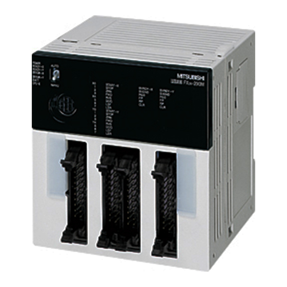
2. Outline of the unit
The FX
-10GM positioning controller (hereinafter call FX
2N
that enables the positioning control of a stepping motor or a servo motor via the drive unit.
•
One FX
-20GM can control 2 axes.
2N
•
Both dedicated positioning language (cod instructions) and sequence language (basic instructions
and application instructions) are available.
•
A pulse generator can be connection.(The manual pulse generators must be an open collector output
type.)
•
The zero return operation at each start can be omitted with a servo amplifier with the absolute position
(ABS) detection function.
•
The FX
-10GM can be used alone. When an FX
2N
series Programmable controller (here after call PLC), reading and writing the positioning data can be
done. (When FX
3. External dimensions
87(3.43)
74(2.91)
-20GM HARDWARE PROGRAMMING MANUAL
-10GM and FX
2N
-10GM is connected with the FX
2N
13(0.51)
POWER
READY
AUTO
ERROR
CPU-E
MANU
Power supply
cable
-10GM positioning controller.
2N
-20GM and wiring and the instructions are explained.
2N
-10GM or 10GM) is a pulse chain output unit
2N
-10GM is connected with an FX
2N
series PLC, an FX
2NC
60(2.36)
FX -10GM
2N
START
STOP
ZRN
SVRDY
FWD
SVEND
RVS
PGO
DOG
FP
LSF
RP
LSR
CLR
X0
X1
X2
X3
Y0
Y1
Y2
Y3
Y4
Y5
FX
-10GM
2N
USER'S GUIDE
JY992D77701B
-CNV-IF is necessary.)
2NC
Din rail width: 35mm
Weight: approx.0.3kg
Dimensions mm(inch)
-10GM,
2N
or FX
2N
2NC
Advertisement
Table of Contents

Related Manuals for Mitsubishi FX2N-10GM


Summary of Contents for Mitsubishi FX2N-10GM
- Page 1 -10GM USER’S GUIDE JY992D77701B This manual only describes the specifications for FX -10GM positioning controller. For complete operation, wiring, mounting and programming instructions please refer to the FX -10GM, -20GM HARDWARE PROGRAMMING MANUAL, FX PROGRAMMING MANUAL and FX SERIES HARDWARE MANUAL. These manuals should be read and understood before attempting to install or use the unit.
- Page 2 4. Product composition 4.1 Each part name The name and description of each part of the FX -10GM are explained below. Operation indicator LED MANU/AUTO switch POWER Connector for programming tool READY AUTO FX -10GM ERROR CPU-E START STOP SVRDY MANU SVEND I/O display...
- Page 3 4.5 Connection with PLC Refer to the FX -10GM, FX -20GM HARDWARE PROGRAMMING MANUAL for details concerning the system configuration. -CNV-IF -10GM Main unit -16EX GM-5EC (I/O Extension of main unit of the PLC) The FX -GM-5EC cable is used to connect the FX -10GM to an FX PLC.
- Page 4 5. Specification 5.1 Power supply specification Item Contents Power supply DC24V -15%, +10% Allowance power The operation is continued to the momentary power failure is 5ms or less. failure time Power consumption 5.2 General specifications Item Contents 0 to 55 °C (operation). -20 to 70 °C (storage). Ambient temperature Surrounding humidity 35 to 85%,No condensation (operation).
- Page 5 Item Contents Program method: The program is written in the FX -10GM by a special programming tool, and the positioning control is done. Control method Table method : When the PLC is used together, the positioning control is done by the FROM/TO instruction. Program No.
- Page 6 All examples and diagrams shown in this manual are intended only as an aid to understand- ing the text, not to guarantee operation. Mitsubishi Electric will accept no responsibility for actual use of the product based on these illustrative examples.
Need help?
Do you have a question about the FX2N-10GM and is the answer not in the manual?
Questions and answers