Table of Contents
Advertisement
Quick Links
Advertisement
Table of Contents

Related Manuals for Mitsubishi FX2N-10GM


Summary of Contents for Mitsubishi FX2N-10GM
- Page 1 HARDWARE / PROGRAMMING MANUAL -10GM, FX -20GM...
- Page 2 • If in doubt about the operation or use of the communication facilities of FX -10GM, FX 20GM units please consult the nearest Mitsubishi Electric distributor. • This manual is subject to change without notice.
- Page 3 FX Series Positioning Controllers -10GM, FX -20GM Hardware / Programming Manual Manual number : JY992D77801 Manual revision : B Date : February 2000...
- Page 4 FX Series Positioning Controllers...
- Page 5 FX Series Positioning Controllers FAX BACK Mitsubishi has a world wide reputation for its efforts in continually developing and pushing back the frontiers of industrial automation. What is sometimes overlooked by the user is the care and attention to detail that is taken with the documentation. However,to continue this process of improvement, the comments of the Mitsubishi users are always welcomed.
- Page 6 FX Series Positioning Controllers...
- Page 7 FX Series Positioning Controllers Guidelines for the Safety of the User and Protection of the FX -10GM, FX 20GM unit This manual provides information for the use of the FX -10GM, FX -20GM Units. The man- ual has been written to be used by trained and competent personnel. The definition of such a person or persons is as follows;...
- Page 8 • All examples and diagrams shown in this manual are intended only as an aid to understand- ing the text, not to guarantee operation. Mitsubishi Electric will accept no responsibility for actual use of the product based on these illustrative examples.
-
Page 9: Table Of Contents
1. Introduction....................1-1 1.1 Introduction Procedure and Reference Manuals ..........1-1 1.2 Outline of Product....................1-2 1.3 Outline dimensions ....................1-3 1.4 Product composition .................... 1-4 1.4.1 Part names ........................ 1-4 1.4.2 Installation method ....................1-5 1.4.3 MANU/AUTO selector switch ..................1-5 1.4.4 Connecting the PLC main unit................... - Page 10 5. Program format ..................5-1 5.1 Positioning program..................... 5-1 5.2 Subtask program ....................5-3 5.3 Instruction List and Execution Time..............5-5 5.3.1 Instruction list ......................5-5 5.3.2 Instruction execution time and startup time ............... 5-7 5.4 General Rules for Positioning Control Instructions ..........5-9 5.4.1 m code instruction format ..................
- Page 11 5.10.18FNC26 (WAND): Logical product, FNC27 (WOR): Logical sum, FNC28 (WXOR): Logical equivalence ..............5-58 5.10.19FNC29 (NEG): Complement................... 5-59 5.10.20FNC72 (EXT): Time-sharing reading of digital switches......... 5-60 5.10.21FNC74 (SEGL): 7-segment time sharing display............ 5-62 5.10.22FNC90 (OUT): Output..................... 5-65 5.10.23FNC92 (XAB), FNC93 (YAB): Absolute position detection........5-66 6.
- Page 12 9. Program Examples ................9-1 9.1 Configuration of Model System ................9-1 9.2 Setting of Parameters ..................9-2 9.2.1 Command pulse frequency and maximum operation speed ........9-2 9.2.2 System of units ......................9-3 9.2.3 Pulse rate and feed rate .................... 9-3 9.2.4 Setting of parameters ....................
-
Page 13: Introduction
FX Series Positioning Controllers Introduction 1 Introduction Introduction Procedure and Reference Manuals Introduction procedure Purchase of product The FX -10GM/20GM is packed together with the following accessories. Confirmation of accessories Power cable After purchasing the -100MPCB 1 cable product, make sure at first -100BPCB (only in FX -20GM) that all accessories are... -
Page 14: Outline Of Product
FX Series Positioning Controllers Introduction 1 Reference manuals 1) E-20TP Operation Manual This manual describes inputs, monitoring and tests of programs using the E-20TP . 2) FX-PCS-KIT-GM-EE Operation Manual This manual describes inputs, monitoring and tests of programs using a personal computer and the FX-PCS-KIT-GM-EE. -
Page 15: Outline Dimensions
FX Series Positioning Controllers Introduction 1 Outline dimensions -10GM -20GM... -
Page 16: Product Composition
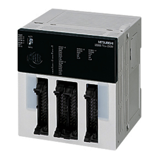
FX Series Positioning Controllers Introduction 1 Product composition 1.4.1 Part names The name and description of each part of the FX -10GM are explained below. Operation indicator LED Hook for DIN rail installation MANU/AUTO switch Connector for motor amplifier: CON2 Connector for programming tool Connector for I/O: CON1 I/O display... -
Page 17: Installation Method
FX Series Positioning Controllers Introduction 1 1.4.2 Installation method The positioning unit can be directly attached to a DIN rail DIN46277 (width: 35 mm). When removing the positioning unit, slightly pull out the DIN rail hook. When the DIN rail hook is pulled out by one more step, it can be locked in the open status. When using an extension block for the Extension Series together with the FX... - Page 18 FX Series Positioning Controllers Introduction 1 • Make sure to shut down the power supplies of all phases on the outside before starting installation or wiring. If the power supplies are not shut down, you may get electrical shock or the unit may be damaged.
-
Page 19: Connecting The Plc Main Unit
FX Series Positioning Controllers Introduction 1 1.4.4 Connecting the PLC main unit Connect the PLC main unit and the positioning unit with a PLC connection cable FX -GM- 5EC (which is offered as an accessory) or FX -GM-65EC (which is separately sold). •... -
Page 20: System Configuration And I/O Assignment
FX Series Positioning Controllers Introduction 1 1.4.5 System configuration and I/O assignment -10GM The FX -10GM is equipped with a power supply, a CPU, operation system inputs, mechanical system inputs and an I/O drive unit. It can also operate inclependantly. The FX -10GM is equipped with four input points (X0 to X3) and six output points (Y0 to Y5) for general purpose, and can be connected to external I/O equipment. - Page 21 FX Series Positioning Controllers Introduction 1 -20GM The FX -20GM is equipped with a power supply, CPU, operation system inputs, mechanical system inputs and an I/O drive unit. It can also operate independently. The FX -20GM is equipped with eight input points (X00 to X07) and eight output points (Y00 to Y07) for general purpose, and can be connected to external I/O equipment.
- Page 22 FX Series Positioning Controllers Introduction 1 I/O assignment When independently using the FX -20GM: In addition to 16 I/O points (8 input points and 8 output points) built in to the FX -20GM, up to 48 I/O points can be added. (Accordingly, up to 64 points in total are available.) Extended inputs and extended outputs are separately assigned from the one nearest to the FX -20GM unit.
-
Page 23: Status Indication
FX Series Positioning Controllers Introduction 1 1.4.6 Status indication LEDs provided on the positioning unit indicate the status of the unit. Table 1.1: Status indication -10GM -20GM Lit while power is normally supplied.If this LED is not lit even while power is supplied, POWER supply voltage may be abnormal or power circuit may be abnormal caused by invasion of conductive foreign objects, etc. -
Page 24: I/O Connector
FX Series Positioning Controllers Introduction 1 1.4.7 I/O connector -10GM All terminals with identical names are shorted internally. (Ex. COM1-COM1, VIN-VIN, etc.) Do not wire " y " terminals. Refer to the FX -10GM, FX -20GM HARDWARE PROGRAMMING MANUAL for wiring information. - Page 25 FX Series Positioning Controllers Introduction 1 Signals in connectors Table 1.2: Signals in connectors -10GM -20GM Abbre- Function/application viation Connector Pin No. Connector Pin No. Automatic operation start input In ready status (while pulses are not output) in AUTO 1 (Y) START mode, when START signal turns ON from OFF, start com- 11(X)
- Page 26 FX Series Positioning Controllers Introduction 1 Table 1.2: Signals in connectors -10GM -20GM Abbre- Function/application viation Connector Pin No. Connector Pin No. General-purpose inputs Through parameters, these pins can be assigned to inputs of digital switch, m code OFF command, manual pulse generator, absolute position (ABS) detection data, step mode, etc.
- Page 27 FX Series Positioning Controllers Introduction 1 *1:In the table 1.2, "(X)" indicates assignment for the X axis, and "(Y)" indicates assignment for the Y axis. -10GM ..CON1:Connector dedicated to I/O CON2: Connector to connect a drive unit -20GM ..CON1: Connector dedicated to I/O CON2: Connector dedicated to I/O CON3: Connector to connect a drive unit (for the X axis) CON4: Connector to connect a drive unit (for the Y axis)
-
Page 28: System Configuration
The figure below shows the system configuration to use the positioning unit. Servo amplifier/drive Motor unit (manufactured (manufactured by Programming tool E-20TP-E -10GM by Mitsubishi or for Mitsubishi or for (E-20TP-E-SET0 sold separately) -20GM general-purpose) general-purpose) Connection cable Connection cable... - Page 29 FX Series Positioning Controllers Introduction 1 g Connection cable to connect general-purpose I/O equipment/terminal block (sold sepa- rately) FX-16E-150CAB: Flat cable with connector on each end (1.5 m) FX-16E-300CAB: Flat cable with connector on each end (3.0 m) FX-16E-500CAB: Flat cable with connector on each end (5.0 m) FX-16E-150CAB-R: Round multi-core cable with connector on each end (1.5 m) FX-16E-300CAB-R: Round multi-core cable with connector on each end (3.0 m) FX-16E-500CAB-R: Round multi-core cable with connector on each end (5.0 m)
-
Page 30: Pin Assignment And Connection Diagram Of Each Cable
FX Series Positioning Controllers Introduction 1 Pin Assignment and Connection Diagram of Each Cable Connection cable FX-20P-CAB0 MINI-DIN 8-pin male MINI-DIN 8-pin male connector connector RS-232C connection cable F -232CAB MINI-DIN 25-pin male MINI-DIN 25-pin male connector connector RS-232C connection cable F -232CAB-1 MINI-DIN 25-pin male D-SUB 9-pin female... - Page 31 FX Series Positioning Controllers Introduction 1 RS-422 connection cable FX-422CAB0 MINI-DIN 25-pin male MINI-DIN 8-pin male connector connector Connection cable FX-50DU-CAB0, FX-50DU-CAB0-1M, FX-50DU-CAB0-10M, FX-50DU-CAB0-20M, FX-50DU-CAB0-30M and FX-50DU-CAB0L MINI-DIN 9-pin male MINI-DIN 8-pin male connector connector 1-19...
- Page 32 FX Series Positioning Controllers Introduction 1 Cable to connect MR-C E-GMC-200CAB Cable to connect MR-J E-GMJ-200CAB • The figures above indicate the pin assignment when the connector is seen from the side on which the positioning unit/extension block/terminal block is connected (engaged). 1-20...
- Page 33 FX Series Positioning Controllers Introduction 1 Cable to connect MR-J2 E-GMJ2-200CAB1A Cable to connect MR-H E-GMH-200CAB • The figures above indicate the pin assignment when the connector is seen from the side on which the positioning unit/extension block/terminal block is connected (engaged). 1-21...
- Page 34 FX Series Positioning Controllers Introduction 1 Cable to connect general-purpose drive unit E-GM-200CAB I/O cables FX-16E-150CAB, FX-16E-300CAB, FX-16E-500CAB, FX-16E-150CAB-R, FX-16E-300CAB-R, FX-16E-500CAB-R • The figures above indicate the pin assignment when the connector is seen from the side on which the positioning unit/extension block/terminal block is connected (engaged). 1-22...
- Page 35 Model name and configuration of I/O connector Applicable electric wire and tool Included parts Crimp tool Model name in (manufactured by Electric wire size (manufactured by Mitsubishi Daiichi Denshi) Daiichi Denshi) -I/O-CON for flat Crimp connector FRC2- AWG28 (0,1 mm ), 1.27 Main body 357J-4674D...
-
Page 36: Terminal Block
FX Series Positioning Controllers Introduction 1 Terminal Block A terminal block converts the I/O area of a positioning unit or a connector type extension block from a connector into a terminal block. The following terminal blocks are available. FX-16E-TB : For both input and output, 16 points, can be connected to positioning unit and extension block FX-32E-TB : For both input and output, 32 points, can be connected to... -
Page 37: I/O Specifications Of Terminal Block (Ac Input Type)
FX Series Positioning Controllers Introduction 1 1.7.2 I/O specifications of terminal block (AC input type) Table 1.4: I/O specifications of terminal block (AC input type ) Model FX-16E-A1-TB (AC input type) Input signal voltage 100 to 120V AC+10%-15%, 50/60 Hz Input signal current 6.2 mA / 110V AC, 60 Hz or 4.7 mA / 100V AC, 50 Hz Input ON current... -
Page 38: Internal Connection Diagram Of Terminal Block
FX Series Positioning Controllers Introduction 1 1.7.4 Internal connection diagram of terminal block FX-16E-TB Connector pin No. (20) (10) (11)(12)(13) (14) (15)(16)(17) (18) (19) (9) (18) (8) (17) (7) (16) (6) Notch (15) (5) (14) (4) (13) (3) (12) (2) (11) (1) Terminal block 1-26... - Page 39 FX Series Positioning Controllers Introduction 1 FX-32E-TB Connector pin No. (20) (10) (11)(12)(13) (14) (15)(16)(17) (18) (19) (9) (18) (8) (17) (7) (16) (6) Notch (15) (5) (14) (4) (13) (3) (12) (2) (11) (1) Terminal block Connector pin No. (20) (10) (11)(12)(13) (14) (15)(16)(17) (18)
- Page 40 FX Series Positioning Controllers Introduction 1 FX-16EX-A1-TB Connector (11) ~ (14) (15) ~ (18) pin No. (20) (10) (19) (9) (18) (8) (17) (7) (16) (6) Photocoupler power supply (15) (5) (14) (4) (13) (3) 1kΩ (12) (2) (11) (1) Terminal block DC24V +10% -15%...
- Page 41 FX Series Positioning Controllers Introduction 1 FX-16EYS-TB Surge absorber is connected to each output point. Connector pin No. (3) (4) (7) (8) (11) (12) (13) ( 14) (15) (16) (17) ( 18) (20) (10) Power (19) (9) supply for (18) (8) photo- (17) (7) thyristor...
- Page 42 FX Series Positioning Controllers Introduction 1 FX-16EYT-H-TB Surge absorber is connected to each output point. Connector pin No. (3) (4) (7) (8) (11) (12) (13) ( 14) (15) (16) (17) ( 18) (20) (10) (19) (9) Photocou- (18) (8) pler power (17) (7) supply (16) (6)
-
Page 43: Terminal Block Layout
FX Series Positioning Controllers Introduction 1 1.7.5 Terminal block layout The terminal layout in the terminal block varies depending on the connector of the connected positioning unit or extension block. Major terminal layout combinations are shown below. In any cases not shown below, assign the terminal layout while referring to "1.7.4 Internal con- nection diagram of terminal block". - Page 44 FX Series Positioning Controllers Introduction 1 -16EX(The first) → FX-16E-TB (connected with FX-16E-{{{CAB) -16EX(The second) → FX-16E-TB (connected with FX-16E-{{{CAB) -16EX(The third) → FX-16E-TB (connected with FX-16E-{{{CAB) -16EYT(The first) → FX-16E-TB (connected with FX-16E-{{{CAB) -16EYT(The second) → FX-16E-TB (connected with FX-16E-{{{CAB) -16EYT(The third) →...
- Page 45 FX Series Positioning Controllers Introduction 1 CN1 of the MR-JA servo amplifier → FX-16E-TB (connected with E-GMH-200CAB) CN1 of the MR-HA servo amplifier → FX-16E-TB (connected with E-GMH-200CAB) 1-33...
- Page 46 FX Series Positioning Controllers Introduction 1 MEMO 1-34...
-
Page 47: Specifications
FX Series Positioning Controllers Specifications 2 Specifications Power Supply Specifications Table 2.1: Power Supply Specifications Item -10GM -20GM Power supply 24V DC -15%, +10% Allowance power The operation is continued if the momentary power failure is 5ms or less. failure time Power consumption Fuse 125V AC... -
Page 48: Performance Specifications
FX Series Positioning Controllers Specifications 2 Table 2.3: Performance Specifications Item -10GM -20GM Accumulation -2,147,483,648 to 2,147,483,647 pulses address 200kHz max., 153,000cm/min (200kHz or less). Automatic trapezoidal pattern Speed instruction acceleration/deceleration (The interpolation drive is 100kHz or less). Manual operation or automatic operation. The DOG type machine zero return Zero return (The DOG search function is provided). - Page 49 FX Series Positioning Controllers Specifications 2 Table 2.3: Performance Specifications Item -10GM -20GM Inputs: X0 to X67, X372 to X377 Out- Inputs: X0 to X3, X375 to X377 puts:Y0 to Y67, Outputs: Y0 to Y5, Supplementary relay: M0 to M99 (gen- Supplementary relay: M0 to M511 eral purpose), M100 to M511 (general (general purpose), M9000 to M9175...
-
Page 50: Input Specification
FX Series Positioning Controllers Specifications 2 Input Specification Table 2.4: Input Specification Input from general-purpose Item Input from drive unit equipment START, STOP , ZRN, FWD, RVS, LSF, Group 1 SVRDY, SVEND Group 2 General-purpose input: X00 to X03 (FX -10GM) Input signal ... - Page 51 FX Series Positioning Controllers Specifications 2 Each signal fetch timing Table 2.5: Each signal fetch timing MANU mode AUTO mode Input signals Motor stopped Motor running Motor stopped Motor running Continuously mon- Continuously mon- SVRDY Before drive. Before drive. itored itored ...
-
Page 52: Output Specification
FX Series Positioning Controllers Specifications 2 Output Specification Table 2.6: Output Specification Item General-purpose output Output to drive unit Signal name Y00 to Y07 FP , RP, CLR Output circuit configuration Circuit isolation By photocoupler Operation indication LED is lit while output is ON External power supply 5 to 24V DC ±... -
Page 53: Wiring
FX Series Positioning Controllers Wiring 3 Wiring This section describes the wiring related to the positioning unit. After finishing wiring, it is recommended to check the wiring by JOG operation before writing a program. (At this time, set the positioning unit to the MANU mode. The JOG speed is deter- mined by the setting of PARA. - Page 54 FX Series Positioning Controllers Wiring 3 • Make sure to shut down the power supplies of all phases on the outside before starting installation or wiring. If the power supplies are not shut down, you may get electrical shock or the unit may be damaged.
- Page 55 FX Series Positioning Controllers Wiring 3 When connecting the positioning unit to the PLC Extension block -10GM for input (only in FX-30DU-GM (AC power supply) -20GM Drive unit -20GM) Input Class 3 grounding 24V DC 100V~240V AC 24V DC -15% -15% -15% +10%...
- Page 56 FX Series Positioning Controllers Wiring 3 • Make sure to shut down the power supplies of all phases on the outside before starting installation or wiring. If the power supplies are not shut down, you may get electrical shock or the unit may be damaged.
-
Page 57: Wiring Of I/O
FX Series Positioning Controllers Wiring 3 Wiring of I/O 3.2.1 Example of wiring of input -10GM -20GM • Input circuit When an input terminal and a COM terminal are connected with no-voltage contact or NPN open collector transistor, the input turns on. Two or more input COM terminals are con- nected inside the PLC. - Page 58 FX Series Positioning Controllers Wiring 3 • Input sensitivity The input current of the positioning unit is 24V DC, 7 mA. However, in order to securely turn on the positioning unit, the input current should be 4.5 mA or more. In order to securely turn off the positioning unit, the input current should be 1.5 mA or less.
- Page 59 FX Series Positioning Controllers Wiring 3 Selecting DC input device Example: Following products manufactured by OMRON Micro switch: Z, V, D2RV Proximity switch: TL, E2M Operation switch: A3P Photoelectric switch:E3S, E3N Imperfect contact may occur when a switch for large current is used. Input device with diodes connected in series Make sure that the voltage drop of the diodes connected in series is approximately 4 V or less.
-
Page 60: Output Connection Example
FX Series Positioning Controllers Wiring 3 3.2.2 Output connection example • In the positioning unit, use COM1 for both input and output (common I/O). • For pairs of inputs such as forward/reverse rotation contacts which would pose a hazard if turned ON simultaneously, provide external interlocks, in addition to interlocks in the program inside the positioning unit, to ensure that they cannot be turned ON simulta- neously. - Page 61 FX Series Positioning Controllers Wiring 3 • Output terminals: The output terminals of the positioning unit are located in a 16-point connector in which both inputs and outputs are located. The power supply for driving the loads must be 5 to 30V DC smoothed power supply. •...
-
Page 62: Operation Input Wiring
FX Series Positioning Controllers Wiring 3 3.2.3 Operation input wiring *1:In simultaneous 2-axis operation, connect either of the X and Y axes. *2:In AUTO mode (while the MANU input is OFF), the input terminals [ZRN], [FWD] and [RVS] can be used as general purpose inputs. 3-10... -
Page 63: Drive System/Mechanical System I/O Wiring
FX Series Positioning Controllers Wiring 3 3.2.4 Drive system/mechanical system I/O wiring 3-11... -
Page 64: Manual Pulse Generator Wiring
FX Series Positioning Controllers Wiring 3 3.2.5 Manual pulse generator wiring This section explains the wiring when a manual pulse generator is used. When a manual pulse generator is used, parameter settings are required. In the wiring shown below, the parameters are set as follows. PARA 39 : Manual pulse generator Set to "1"... -
Page 65: Absolute Position (Abs) Detection Wiring
3.2.6 Absolute position (ABS) detection wiring This section explains the wiring needed when a Mitsubishi MR-H/MR-J2/MR-J2-Super servo motor is connected and the absolute position detection function (ABS) is used. To detect the absolute position, the parameter Nos. 50, 51 and 52 must be set. -
Page 66: I/O Connection Example
FX Series Positioning Controllers Wiring 3 3.2.7 I/O connection example When the FX -10GM is connected to a stepping motor. 3-14... - Page 67 FX Series Positioning Controllers Wiring 3 When the FX -10GM is connected to a MR-C servo motor. 3-15...
- Page 68 FX Series Positioning Controllers Wiring 3 When the FX -10GM is connected to a MR-J servo motor. 3-16...
- Page 69 FX Series Positioning Controllers Wiring 3 When the FX -10GM is connected to a MR-J2 servo motor. 3-17...
- Page 70 FX Series Positioning Controllers Wiring 3 When the FX -10GM is connected to a MR-H servo motor. 3-18...
- Page 71 FX Series Positioning Controllers Wiring 3 When the FX -20GM is connected to a stepping motor. 3-19...
- Page 72 FX Series Positioning Controllers Wiring 3 When the FX -20GM is connected to a MR-C servo motor. 3-20...
- Page 73 FX Series Positioning Controllers Wiring 3 When the FX -20GM is connected to a MR-J servo motor. 3-21...
- Page 74 FX Series Positioning Controllers Wiring 3 When the FX -20GM is connected to the MR-J2 servo motor. 3-22...
- Page 75 FX Series Positioning Controllers Wiring 3 When the FX -20GM is connected to the MR-H servo motor. 3-23...
- Page 76 FX Series Positioning Controllers Wiring 3 MEMO 3-24...
-
Page 77: Parameters
FX Series Positioning Controllers Parameters 4 Parameters Notes on Parameters in General Set parameters to determine the operating condition of the positioning unit. The positioning unit can satisfy diversified needs through parameter setting in accordance with the operation specifications and the control specifications. Parameters are mainly classified into the following three types. - Page 78 FX Series Positioning Controllers Parameters 4 With some exceptions, each parameter is assigned a special data register (special D). When parameters are set from the panel of a peripheral unit, the same data is simultaneously set in the special Ds. The data in the special Ds can be changed using the positioning program during operation.
-
Page 79: Parameter List
FX Series Positioning Controllers Parameters 4 Parameter List Table 4.1: Parameter List PARA. Initial Item Description ([ ]: unit) value 0: Mechanical system of units System of unit 1: Motor system of units 2: Composite system of units 1 to 65,535 [PLS/REV] 2,000 Pulse rate 1 to 999,999... - Page 80 FX Series Positioning Controllers Parameters 4 Table 4.1: Parameter List PARA. Initial Item Description ([ ]: unit) value 0: Normally open contact (A - contact) DOG input logic 1: Normally closed contact (B - contact) 0: Normally open contact (A - contact) LS logic 1: Normally closed contact (B - contact) Error judgement time 0 to 5,000 ms (When "0"...
- Page 81 FX Series Positioning Controllers Parameters 4 Table 4.1: Parameter List PARA. Initial Item Description ([ ]: unit) value 0: Program No. 0 (fixed) 1: 1 digit of digital switch (0 to 9) Program No. specifi- cation method 2: 2 digits of digital switch (00 to 99) 3: Specified by special data registers (D9000, D9010) Head No.
- Page 82 FX Series Positioning Controllers Parameters 4 Table 4.1: Parameter List PARA. Initial Item Description ([ ]: unit) value -20GM:X0 to X67, X372 to X377 (One points are occupied.) Step mode input No. -10GM:X0 to X3, X375 to X377 (One points are occupied.) ...
- Page 83 FX Series Positioning Controllers Parameters 4 Table 4.1: Parameter List PARA. Initial Item Description ([ ]: unit) value 20GM:0 0: 8K step, 1: 4K step Memory size In FX -10GM, only "1 (4K step)" is available. 10GM:1 File register 0 to 3,000 [points] (assigned by D4,000 to D6,999) 0:Lights LED, and does not make GM give output (M9127 : OFF).
-
Page 84: Positioning Parameters
FX Series Positioning Controllers Parameters 4 Positioning Parameters 4.3.1 Positioning Parameters Setting the units used PARA. 0: System of units Set the units used for the position and the speed. Table 4.2: System of units -10GM -20GM Setting = "0" :Controls the position based on "mm, deg, 1/10 inch, etc.", which is called the mechani- cal system of units. - Page 85 FX Series Positioning Controllers Parameters 4 PARA. 2: Feed rate (The feed rate is expressed as "B".) Set the travel of the machine per rotation of the motor. Table 4.5: Feed rate -10GM -20GM 1 to 999,999 µm/REV 1 to 999,999 mdeg/REV 1 to 999,999 ×...
- Page 86 FX Series Positioning Controllers Parameters 4 Concept of mechanical system of units When PARA. 0 (system of units) is set to "0" or "2", the mechanical system of units ("mm", "deg", "inch", etc.) is selected. At this time, there is no parameter to select either one among "mm", "deg", "inch", etc.
- Page 87 For example, the command pulse frequency required to operate the HC-MF Series servo motor manufactured by Mitsubishi at the rated rotation speed of 3,000 rev/ min can be obtained as follows. (Suppose that the electronic gear ratio is the initial value "1/1".) Command pulse frequency [Hz] (open collector type) f0 = Pt ×...
- Page 88 FX Series Positioning Controllers Parameters 4 The table below shows the setting of major electronic gears and pulse rates obtained by the above calculation. Table 4.7: Setting of major electronic gears and pulse rates Command pulse Command pulse frequency (100 kHz) Servo amplifier Rated frequency (200 kHz)
- Page 89 FX Series Positioning Controllers Parameters 4 PARA. 4: Maximum speed Set the maximum speed in this parameter. When the speed is not specified in a positioning program, the machine operates at the speed set here. Other speeds must be set to a value equivalent to or less than this maximum value.
- Page 90 FX Series Positioning Controllers Parameters 4 PARA. 7: Backlash compensation (Valid exclusively for the cod 00 instruction.) When the rotation direction is reversed by the cod 00 (DRV) instruction, the compensation quantity set to this parameter is automatically added to the travel quantity, then positioning is performed.
- Page 91 FX Series Positioning Controllers Parameters 4 PARA. 10: Interpolation time constant Set the time required to achieve the speed specified by the program. (The bias speed is always regarded as "0".) This parameter is valid while interpolation control is performed in the FX 20GM.
- Page 92 FX Series Positioning Controllers Parameters 4 PARA. 11: Pulse output format Set the pulse output format for the drive unit. Table 4.15: Pulse output format -10GM -20GM Setting = "0": Forward rotation pulses and reverse rotation pulses. Setting = "1": Rotation pulses and direction specification (Interpolation operations are not possible). Refer to figures below for the pulse format.
- Page 93 FX Series Positioning Controllers Parameters 4 PARA. 15: Zero return direction Set the direction in which the machine travels when the zero return instruction is given. Table 4.20: Zero return direction -10GM -20GM Setting = "0" : Direction in which the present value increases. Setting = "1"...
- Page 94 FX Series Positioning Controllers Parameters 4 PARA. 20: Limit switch logic Set the logic of the limit switch (LS) used to confirm the machine operation limit. Apart from the limit switches, software limits (set by PARA. 25 and PARA. 26) are also available. Table 4.25: Limit switch logic -10GM -20GM...
- Page 95 FX Series Positioning Controllers Parameters 4 PARA. 21: Positioning completion error evaluation time If the positioning completion signal is not entered within the time set to this parameter when output of pulses is finished, a servo end error occurs. When the servo end check instruction (cod 09 (CHK)) or an instruction (cod 00 (DRV), cod 28 (DRVZ), etc.
- Page 96 FX Series Positioning Controllers Parameters 4 PARA. 23: Stop mode Set the operation mode of the positioning program when the stop instruction is entered (that is, when the external input terminal [STOP] or the special auxiliary relays M9002 for the X axis and M9018 for the Y axis is turned ON.
- Page 97 FX Series Positioning Controllers Parameters 4 Operation caused by STOP command Table 4.29: Operation caused by STOP command Operation caused by STOP command Setting 10GM 20GM Remaining distance Timer m code The machine does not The machine does not 0, 4 Not changed stop stop...
- Page 98 FX Series Positioning Controllers Parameters 4 PARA. 26: Software limit (lower) When the present value becomes equal to or less than the set value, a limit error occurs. Table 4.32: Software limit (lower) -10GM -20GM Set a 32-bit value within the following range. -2,147,483,648 to +2,147,483,647 •...
-
Page 99: I/O Control Parameters
FX Series Positioning Controllers Parameters 4 4.3.2 I/O Control Parameters This section explains the settings of the parameters to read the program No., output the m code and detect the absolute position by utilizing the general purpose I/Os of the positioning unit. - Page 100 FX Series Positioning Controllers Parameters 4 When PARA. 30 is set to "2", attach 50 V, 0.1 A diodes to the digital switch to prevent revolving paths. The DSW data to specify the program No. to be executed is automatically read immediately after the START command is given even if the EXT instruction is not given.
- Page 101 FX Series Positioning Controllers Parameters 4 PARA. 34: Ready (RDY) output valid Set whether or not to output the ready (preparation completion) signal of the positioning unit. Table 4.37: Ready (RDY) output valid -10GM -20GM Setting = "0" : Invalid Setting = "1"...
- Page 102 FX Series Positioning Controllers Parameters 4 Example of a program in which output of m code to the outside is used The program below shows an example of control in which auxiliary unit control commands are transferred to the PLC by I/O signals while using the FX -20GM and a general PLC.
- Page 103 FX Series Positioning Controllers Parameters 4 Program in the programmable controller BIN [P] K2X20 m code → ON signal (X27 to X20)BCD D 0(BIN) DECO M 00 → Decode D0(7bit) (M99 to M00) M 00 WAIT indication M 01 X 31 Auxiliary equipment No.1 M 02...
- Page 104 FX Series Positioning Controllers Parameters 4 PARA. 41: Division rate for multiplied result The input pulses multiplied by the value set to PARA. 40 are divided by the value set here. Table 4.44: Division rate for multiplied result -10GM -20GM ...
- Page 105 FX Series Positioning Controllers Parameters 4 • While manual pulse generators are used, the interrupt input No. from cod31 or cod72 instruction is not available because the input No. from the manual pulse generators overlaps the interrupt input No. from cod31 or cod72 instruction. The interrupt input No.
- Page 106 FX Series Positioning Controllers Parameters 4 PARA. 52: Head output No. for ABS control Set the head output No. of the destination for the absolute position data control. Table 4.49: Head output No. for ABS control -10GM -20GM Y0 to Y3 (Three points are occupied.) Y0 to Y3 (Three points are occupied.) Specified device No.
- Page 107 FX Series Positioning Controllers Parameters 4 PARA. 56: General purpose input declaration for FWD/RVS/ZRN The dedicated inputs FWD (forward rotation JOG), RVS (reverse rotation JOG) or ZRN (zero return) can be used as general purpose inputs. When X372 to X377 (X375 to X377 in the FX -10GM) are used for general purpose inputs in the parameters or the programs, this parameter must be set properly.
-
Page 108: System Parameters
FX Series Positioning Controllers Parameters 4 4.3.3 System Parameters The system parameters set the positioning program memory size, the number of file registers, the battery status and items related to subtasks. PARA. 100: Memory size Set the program memory size. Table 4.55: Memory size -10GM -20GM... - Page 109 FX Series Positioning Controllers Parameters 4 PARA. 103: Battery status output No. Set the output No. in the FX -20GM when PARA. 102 is set to "2". Table 4.58: Battery status output No. -10GM -20GM Setting = Output relay (Y) No. in a range of 0 to 67. Initial value=0 PARA.
- Page 110 FX Series Positioning Controllers Parameters 4 PARA. 108: Subtask error Set whether or not the positioning unit outputs an error when the error occurs in the subtask. Table 4.63: Subtask error -10GM -20GM Setting = "0" :Does not output from the positioning unit when an error occurs (initial value). Setting = "1"...
-
Page 111: Program Format
FX Series Positioning Controllers Program format 5 Program format Positioning program The positioning program is expressed as follows. Line No. Program No. Ox 10 N0000 cod28(DRVZ); N0001 m00(WAIT); N0002 cod00(DRV) Program x100 f1000; N0003 m00(WAIT); N0100 m02(END); c Line No. •... - Page 112 FX Series Positioning Controllers Program format 5 • The END instruction ("m02" for simultaneous 2-axis operation, X axis operation or Y axis operation and "m102" for subtasks) must be provided at the end of each program. • Program No.00 to 99 (100 in total) are available as follows. ("O100" only is available for subtasks.) O00 to O99 Ox00 to Ox99...
-
Page 113: Subtask Program
FX Series Positioning Controllers Program format 5 Subtask program This section explains the subtask which mainly processes programmable controller programs. Main task and subtask • A main task is a positioning program expressed as O, Ox and Oy which performs position- ing in the simultaneous 2-axis mode or independent 2-axis mode (Ox exclusively is avail- able in the FX -10GM.). -
Page 114: Program Examples
FX Series Positioning Controllers Program format 5 Processing of subtasks The subtask is processed one line at a time in the same way as O100 a positioning program. When the START signal is entered, the LD X00; subtask is processed from the first line, and finishes at "m102 Unconditional AND X01;... -
Page 115: Instruction List And Execution Time
FX Series Positioning Controllers Program format 5 Instruction List and Execution Time 5.3.1 Instruction list Table 5.1: Instruction list Instruction Description 10GM 20GM Positioning instructions cod00 DRV Positioning at high speed cod01 LIN Linear interpolation positioning × cod02 CW Circular interpolation positioning (clockwise) ×... - Page 116 FX Series Positioning Controllers Program format 5 Table 5.1: Instruction list Instruction Description 10GM 20GM Sequence control instructions FNC00 CJ Conditional jump FNC01 CJN Negated conditional jump FNC02 CALL Subroutine call FNC03 RET Subroutine return FNC04 JMP Unconditional jump FNC05 BRET Return to bus line FNC08 RPT Repetition start...
-
Page 117: Instruction Execution Time And Startup Time
FX Series Positioning Controllers Program format 5 5.3.2 Instruction execution time and startup time Instruction execution time Basic instructions Table 5.2: Basic instructions [Unit: ms] 10GM 20GM 10GM 20GM Sequence instructions Table 5.3: Sequence instructions [Unit: ms] 10GM 20GM 10GM 20GM FNC00(CJ) FNC20(ADD) - Page 118 FX Series Positioning Controllers Program format 5 Positioning instructions (Instructions generating pulses are described in "Startup time" below.) Table 5.4: Positioning instructions [Unit: ms] -10GM -20GM Motor system Mechanical system Motor system Mechanical system cod29(SETR) cod73(MOVC) cod74(CNTC) ...
-
Page 119: General Rules For Positioning Control Instructions
FX Series Positioning Controllers Program format 5 General Rules for Positioning Control Instructions A command matter of the cod instruction and m code are explained. 5.4.1 m code instruction format m code instructions are used to drive various auxiliary equipment (such as chucks, drills, etc.) in association with positioning operations. -
Page 120: Continuous Paths (Fx 2N -20Gm)
FX Series Positioning Controllers Program format 5 • Only the X axis is available in the FX -10GM. • In the FX -20GM or the FX -10GM, m codes can be transmitted with the FX Series programmable controller using buffer memories. •... - Page 121 FX Series Positioning Controllers Program format 5 Number of continuous paths The number of continuous paths varies depending on the operation of the special auxiliary relay M9015. When the M9015 is OFF While an interpolation operation is performed, preparation for interpolation control for the next process is performed.
- Page 122 FX Series Positioning Controllers Program format 5 Operations of m codes during continuous paths When m codes of the WITH mode are specified in continuous path interpolation instructions, a series of continuous operations are performed even if the m code OFF command is not entered. When a series of operations are completed and the m code OFF command is entered, the machine proceeds to the next operation.
-
Page 123: Multistep Operation Using Continuous Paths (Fx 2N -10Gm)
FX Series Positioning Controllers Program format 5 5.4.3 Multistep operation using continuous paths (FX -10GM). Though the cod 01 (LIN) is a linear interpolation instruction, it can be used for multistep opera- tion by specifying continuous paths in the FX -10GM. - Page 124 FX Series Positioning Controllers Program format 5 m code control during operation at multi-step speed by M9160 (FX -10GM) Operation while an m code is used is equivalent to operation by continuous passes described in the previous page. However, operation is different if the special auxiliary relay M9160 is driven. Outline: When operation at multi-step speed is performed while the special auxiliary relay M9160 in the -10GM is ON, an m code (WITH mode) realizes the following operation.
- Page 125 FX Series Positioning Controllers Program format 5 Use example 2 (M9160 is ON.) N0000 Ox0,N0; N0010 SET M9160; N0011 cod01 xC f100,000 m10; N0012 cod01 xD f200,000; N0013 RST M9160; N0020 m02(END) N0011 N0012 Deceleration range Operation in the use example 2 is equivalent to that in the use example 1. 1) When the m code OFF command is given in the range between the points A and B, the speed changes to the next step.
-
Page 126: Instruction Format
FX Series Positioning Controllers Program format 5 Instruction format (E)Servo end check (D)Instruction group (A)Applicable models cod 00 High speed positioning Applicable models Series name Remarks Remarks Servo end check -10GM DRIVE Instruction group -20GM -10GM -20GM cod 00 cod 00 Basic format X axis... - Page 127 FX Series Positioning Controllers Program format 5 Units of operands The units of the value specified by the operands are determined by the parameters. • Travel (x, y, i, j, r) The motor system (PLS) or the mechanical system (mm, inch, deg) is valid in accordance with the setting of PARA.
- Page 128 FX Series Positioning Controllers Program format 5 (D) Instruction groups In this manual, instructions are classified into four groups (A to D). Group A When the same instruction (same code No.) is used consecutively the code No. can be omitted and only the necessary operands are required. Instruction names : cod00(DRV), cod01(LIN), cod02(CW), cod03(CCW), cod31(INT) Example : N100 cod00(DRV) x100;...
-
Page 129: Drive Control Instructions
FX Series Positioning Controllers Program format 5 Drive Control Instructions This section explains the drive control instructions which function as the basis of positioning control. 5.6.1 cod 00 (DRV): High speed positioning cod 00 Applicable models High speed positioning Series name Remarks Remarks Servo end check... - Page 130 FX Series Positioning Controllers Program format 5 d’ e’ Operation speed Set these operands to operate the machine at a speed less than the maximum speed (set to PARA. 4). If these operands are not set, the machine operates at the maximum speed. When programming, use "f"...
-
Page 131: Cod 01 (Lin): Linear Interpolation Positioning
FX Series Positioning Controllers Program format 5 5.6.2 cod 01 (LIN): Linear interpolation positioning Linear interpolation positioning, cod 01 Applicable models Multi-step operation (10GM) Series name Remarks Remarks Servo end check -10GM LINEAR Instruction group -20GM • -20GM This instruction is not available in the programs (Ox, Oy and O100) for independendent 2-axis operation and cod 01... - Page 132 FX Series Positioning Controllers Program format 5 When the vector speed (f) is omitted, the machine operates at the following speed. (The value is not same PARA.4 (maximum speed)) Table 5.12: Vector speed (f) 10GM 20GM 1st time 200kHz 100kHz 2nd time or Later Previous f value When interpolation instructions are consecutively executed, path operation is performed.
-
Page 133: Cod 02 (Cw), Cod 03 (Ccw): Circular Interpolation With Center Point Specification
FX Series Positioning Controllers Program format 5 5.6.3 cod 02 (CW), cod 03 (CCW): Circular interpolation with center point specification cod 02 Applicable models Circular interpolation with center point specification Series name Remarks Remarks Servo end check -10GM cod 03 Instruction group -20GM -20GM... - Page 134 FX Series Positioning Controllers Program format 5 cod 02 Applicable models Circular interpolation with radius specification Series name Remarks Remarks Servo end check -10GM cod 03 Instruction group -20GM -20GM This instruction is not available in cod 02 the programs (Ox, Oy and O100) for independent 2-axis operation Radius X axis...
- Page 135 FX Series Positioning Controllers Program format 5 Program example cod90 (ABS); Absolute drive method. cod02 (CW) x1000 y1000 i250 j250 f1000; When interpolation instructions are executed consecutively, path operation is performed (Refer to Section 5.4.2.). 5-25...
-
Page 136: Cod 04 (Tim): Stabilization Time
FX Series Positioning Controllers Program format 5 5.6.4 cod 04 (TIM): Stabilization time cod 04 Applicable models Stabilization time (Dwell) T I M Series name Remarks Remarks Servo end check TIMER -10GM Instruction group -20GM -10GM -20GM cod 04 cod 04 Basic format Stabilization time... -
Page 137: Cod 09 (Chk): Servo End Check
FX Series Positioning Controllers Program format 5 5.6.5 cod 09 (CHK): Servo end check cod 09 Applicable models Servo end check Series name Remrks Remarks SERVO Servo end check -10GM Instruction group CHECK -20GM -10GM -20GM cod 09 cod 09 Basic format c CHECK... -
Page 138: Cod 28 (Drvz): Machine Zero Return
FX Series Positioning Controllers Program format 5 5.6.6 cod 28 (DRVZ): Machine zero return cod 28 Applicable modeols Machine zero return DRVZ Series name Remarks Remarks Servo end check -10GM DRIVE TO ZERO Instruction group -20GM -10GM -20GM Basic cod 28 cod 28 format DRVZ... -
Page 139: Cod 29 (Setr): Electrical Zero Point Setting
FX Series Positioning Controllers Program format 5 5.6.7 cod 29 (SETR): Electrical zero point setting cod 29 Applicable models Electrical zero point setting SETR Series name Remarks Remarks Servo end check -10GM RETURN Instruction group ADDRESS -20GM -10GM -20GM cod 29 cod 29 Basic format... -
Page 140: Cod 31 (Int): Interrupt Stop (Ignoring The Remaining Distance)
FX Series Positioning Controllers Program format 5 5.6.9 cod 31 (INT): Interrupt stop (ignoring the remaining distance) cod 31 Applicable models Interrupt stop (ignoring the remaining distance) Series name Remarks Remarks Servo end check INTERRUPT -10GM STOP Instruction group -20GM -10GM -20GM cod 31... - Page 141 FX Series Positioning Controllers Program format 5 Program example (in the FX -20GM) cod 31 (INT) x1500 y1000 f2000; cod 01 (LIN) x2000 y1500 f2000; *1: When the interrupt input X06 is turned ON, the machine is decelerated and stopped. Then, the machine proceeds to the next positioning while ignoring the remaining distance indi- cated in dotted line.
-
Page 142: Cod 71 (Sint): Interrupt Jog Feed (One-Step Speed)
FX Series Positioning Controllers Program format 5 5.6.10 cod 71 (SINT): Interrupt jog feed (one-step speed) cod 71 Applicable models Interrupt jog feed (one-step speed) SINT Series name Remarks Remarks Servo end check -10GM INTERRUPT STOP Instruction group -20GM -10GM -20GM cod 71 cod 71... -
Page 143: Cod 72 (Dint): Interrupt Jog Feed (Two-Step Speed)
FX Series Positioning Controllers Program format 5 5.6.11 cod 72 (DINT): Interrupt jog feed (two-step speed) cod 72 Applicable models Interrupt jog feed (two-step speed) DINT Series name Remarks Remarks Servo end check INTERRUPT -10GM STOP Instruction group -20GM -10GM -20GM cod 72 cod 72... - Page 144 FX Series Positioning Controllers Program format 5 Interrupt Drive Instructions The inputs shown in the table below are assigned as the stop commands and deceleration commands for interrupt drive control. Table 5.15: Interrupt Drive Instructions Input -10GM -20GM cod 72 : x axis speed-change input cod 72 : x axis speed-change input cod 72 : x axis stop input cod 72 : x axis stop input...
-
Page 145: Cod 73 (Movc): Travel Compensation
FX Series Positioning Controllers Program format 5 5.6.12 cod 73 (MOVC): Travel compensation Travel compensation/Center point compensation/ cod 73 Applicable models Radius compensation/Compensation cancel MOVC Series name Remarks Remarks Servo end check -10GM Instruction group -20GM -10GM -20GM cod 73 cod 73 Basic Travel... -
Page 146: Cod 74 (Cntc): Center Point Compensation, Cod 75 (Radc): Radius Compensation
FX Series Positioning Controllers Program format 5 5.6.13 cod 74 (CNTC): Center point compensation, cod 75 (RADC): Radius compensation Travel compensation/Center point compensation/ cod 74 Applicable models Radius compensation/Compensation cancel CNTC Series name Remarks Remarks Servo end check cod 75 -10GM RADC Instruction group... -
Page 147: Cod 76 (Canc): Compensation Cancel
FX Series Positioning Controllers Program format 5 5.6.14 cod 76 (CANC): Compensation cancel Travel compensation/Center point compensation/ cod 76 Applicable models Radius compensation/Compensation cancel CANC Series name Remarks Remarks Servo end check -10GM Instruction group -20GM -10GM -20GM cod 76 cod 76 Basic Compensation cancel... -
Page 148: Cod 90 (Abs): Absolute Address, Cod 91 (Inc): Incremental Address
FX Series Positioning Controllers Program format 5 5.6.15 cod 90 (ABS): Absolute address, cod 91 (INC): Incremental address cod 90 Absolute/Incremental address Applicable models Series name Remarks Remarks Servo end check cod 91 -10GM Instruction group -20GM -10GM -20GM Absolute address cod 90 cod 90 Basic... -
Page 149: Cod 92 (Set): Present Value Change
FX Series Positioning Controllers Program format 5 5.6.16 cod 92 (SET): Present value change cod 92 Applicable models Present value change Series name Remarks Remarks Servo end check -10GM Instruction group -20GM -10GM -20GM Basic cod 92 cod 92 format X axis X axis Y axis... -
Page 150: Common Items In Sequence Control Instructions
FX Series Positioning Controllers Program format 5 Common Items in Sequence Control Instructions This paragraph describes basic instructions (such as LD and AND) and application instructions in sequence control. These instructions are used together with positioning control instructions, and control auxiliary units accompanied by positioning. -
Page 151: Applicable Devices
FX Series Positioning Controllers Program format 5 5.7.2 Applicable devices Table 5.16: Applicable device s -10GM -20GM Main unit Main unit Extension Input relays X00 to X03 4 points X00 to X07 8 points X10 to X67 (X) *5 X375 to X377 3 points *1 X372 to X377 6 points *1 48 points *2... -
Page 152: Bit Devices
FX Series Positioning Controllers Program format 5 5.7.3 Bit devices The devices such as X, Y and M which handle ON/OFF information are called bit devices. Other devices such as D, V and Z which handle numeric data are called word devices. Bit devices, however, can be grouped to handle numeric data. -
Page 153: Data Length And Instruction Execution Format
FX Series Positioning Controllers Program format 5 5.7.4 Data length and instruction execution format Application instructions which handle numerics are either 16-bit or 32-bit depending on the bit length of the numeric data. FNC 12 D 10 D 12 Data is transmitted from (D10) to (D12). FNC 12 D 20 D 22... -
Page 154: Basic Sequence Instructions
FX Series Positioning Controllers Program format 5 Basic sequence instructions The sequence instructions are classified into the basic type and the application type. The for- mat of both types is equivalent to that for the FX Series programmable controller. These sequence instructions are used in positioning programs (including subtasks). Table 5.17: Basic sequence instructions Symbol and Circuit indication and applica-... -
Page 155: Application Instruction Format
FX Series Positioning Controllers Program format 5 Application instruction format In this manual, each application instruction is expressed as follows. Execution format Applicable models FNC 10 Applicable models Transfer Applicable Series name Remarks devices COMPARE -10GM M O V 32-bit operation [D] M O V 16-bit operation 5 steps... - Page 156 FX Series Positioning Controllers Program format 5 f Applicable devices Devices such as X, Y, M and D can be used as operands. X, Y and M can be used as bit devices or word devices (Refer to "5.6.3 Bit devices".). The data registers D (16-bit) and the index registers V (16-bit) and Z (32-bit) are handled as data.
-
Page 157: Description On Sequence Application Instructions
FX Series Positioning Controllers Program format 5 5.10 Description on Sequence Application Instructions This paragraph describes the details of sequence application instructions. 5.10.1 FNC00 (CJ): Conditional jump FNC 00 Applicable models Conditional jump Series name Remarks 16-bit operation CONDITIONAL -10GM 3 steps JUMP -20GM... -
Page 158: Fnc02 (Call): Subroutine Call, Fnc03 (Ret): Subroutine Return
FX Series Positioning Controllers Program format 5 5.10.3 FNC02 (CALL): Subroutine call, FNC03 (RET): Subroutine return FNC 02 Applicable models Subroutine call/Subroutine return CALL Series name Remarks 16-bit operation -10GM FNC 03 3 steps : CALL 1 steps : RET -20GM : Pointers P0 to P127 (in the 10GM) S·... -
Page 159: Fnc05 (Bret): Bus Return
FX Series Positioning Controllers Program format 5 5.10.5 FNC05 (BRET): Bus return FNC 05 Applicable models Bus return BRET Series name Remarks 16-bit operation BRET -10GM 1 steps RETURN -20GM No applicable devices Applicable devices and basic format • When FNC 05 (BUS RETURN)instruction is executed, the FNC 05 instructions after that are treated as those connected to the bus. -
Page 160: Fnc08 (Rpt): Start Of Repeat, Fnc09 (Rpe): End Of Repeat
FX Series Positioning Controllers Program format 5 5.10.6 FNC08 (RPT): Start of repeat, FNC09 (RPE): End of repeat FNC 08 Applicable models Start/End of repeat R P T Series name Remarks REPEAT 16-bit operation -10GM 3 steps : RPT 1 steps :RPE FNC 09 -20GM... - Page 161 FX Series Positioning Controllers Program format 5 Continuous paths and repeat instructions (in the FX -20GM only) If a cod 01, cod 02 or cod 03 instruction is used at the beginning and end of a program delimited by RPT and RPE instructions, these cod instructions are processed as if they are continuing. Using this function, a locus can be tranced repeatedly.
-
Page 162: Fnc10 (Cmp): Comparison
FX Series Positioning Controllers Program format 5 5.10.7 FNC10 (CMP): Comparison FNC 10 Applicable models Comparison Series name Remarks 16-bit operation 32-bit operation COMPARE [D]CMP -10GM 7 steps 11 steps -20GM S1· S2· Word devices devices Applicable D· devices The comparison source and basic S1·... -
Page 163: Fnc12 (Mov): Transfer
FX Series Positioning Controllers Program format 5 5.10.9 FNC12 (MOV): Transfer FNC 12 Applicable models Transfer Series name Remarks 16-bit operation 32-bit operation MOVE [D]MOV -10GM 5 steps 8 steps -20GM S· Word devices Applicable devices When the drive input is ON, the data of D·... -
Page 164: 11Fnc14 (Rmov): Reduction Transfer
FX Series Positioning Controllers Program format 5 5.10.11 FNC14 (RMOV): Reduction transfer FNC 14 Applicable models Reduction transfer RMOV Series name Remarks RMOV 16-bit operation REDUCE -10GM 5 steps MOVE -20GM (not V.) S· Word devices Applicable D· devices (not Z.) Drive and basic input... -
Page 165: 12Fnc18 (Bcd): Bcd Conversion
FX Series Positioning Controllers Program format 5 5.10.12 FNC18 (BCD): BCD conversion FNC 18 Applicable models BCD conversion Series name Remarks 16-bit operation 32-bit operation BINARY CODED [D]BCD -10GM TO DECIMAL 5 steps 8 steps -20GM S· Word devices Applicable D·... -
Page 166: 14Fnc20 (Add): Addition, Fnc21 (Sub): Subtraction
FX Series Positioning Controllers Program format 5 5.10.14 FNC20 (ADD): Addition, FNC21 (SUB): Subtraction FNC 20 Applicable models Addition/Subtraction Series name Remarks 16-bit operation 32-bit operation [S]ADD -10GM FNC 21 7 steps 11 steps [D]SUB -20GM S1· S2· S1· S2· Flags: Described below. -
Page 167: Fnc22 (Mul): Multiplication
FX Series Positioning Controllers Program format 5 5.10.15 FNC22 (MUL): Multiplication FNC 22 Applicable models Multiplication Series name Remarks MULTIPLI 16-bit operation 32-bit operation [D]MUL -10GM CATION 7 steps 11 steps -20GM S1· S2· S1· S2· Word devices Applicable D· devices and basic Drive... -
Page 168: Fnc28 (Wxor): Logical Equivalence
FX Series Positioning Controllers Program format 5 5.10.17 FNC24 (INC): Increment, FNC25 (DEC): Decrement FNC 24 Applicable models Increment/Decrement Series name Remarks INCREMENT 16-bit operation 32-bit operation [D]INC -10GM FNC 25 3 steps 5 steps [D] DEC -20GM DECREMENT D· Change to in a 16-bit operation Word... -
Page 169: 19Fnc29 (Neg): Complement
FX Series Positioning Controllers Program format 5 5.10.19 FNC29 (NEG): Complement FNC 29 Applicable models Complement Series name Remarks 16-bit operation 32-bit operation BINARY [D]NEG -10GM 3 steps 5 steps -20GM Word devices Applicable D· devices and basic Each bit of data in the device specified by D·... -
Page 170: 20Fnc72 (Ext): Time-Sharing Reading Of Digital Switches
FX Series Positioning Controllers Program format 5 5.10.20 FNC72 (EXT): Time-sharing reading of digital switches FNC 72 Applicable models Time-sharing reading of digital switches Series name Remarks 16-bit operation 16-bit operation [D] EXT EXTERNAL -10GM 9 steps 14 steps -20GM Word devices devices... - Page 171 FX Series Positioning Controllers Program format 5 Reading a positive/negative numeric (Not available in the FX -10GM.) When K17 to K24 are used to specify the number of digits, negative numeric values can also be read. S· D1· D2· FNC 72 This instruction performs time-sharing reading of the data from the digital switches.
-
Page 172: 21Fnc74 (Segl): 7-Segment Time Sharing Display
FX Series Positioning Controllers Program format 5 5.10.21 FNC74 (SEGL): 7-segment time sharing display FNC 74 Applicable models 7-segment time sharing display SEGL Series name Remarks SEVEN [D] × 16-bit operation 32-bit operation [D] SEGL SEGL -10GM SEGMENT 9 steps 14 steps -20GM WITH LATCH... - Page 173 FX Series Positioning Controllers Program format 5 4) Logic parameter Refer to "7-segment display logic" on the next page. • The internal binary data is converted into BCD data, then output using the time-sharing method. • This instruction is processed in accordance with an operation cycle.
- Page 174 FX Series Positioning Controllers Program format 5 List of specification of number of digits The I/Os shown in the table below are required for the SEGL instruction in accordance with the number of digits to be displayed. Table 5.20: List of specification of number of digits Reading a positive value Reading a negative value Number of...
-
Page 175: 22Fnc90 (Out): Output
FX Series Positioning Controllers Program format 5 5.10.22 FNC90 (OUT): Output FNC 90 Applicable models Output Series name Remarks 16-bit operation -10GM 3 steps -20GM Bit devices D· Applicable devices • This is an ordinary coil instruction. and basic Drive When this instruction is driven with the contact turned format input... -
Page 176: 23Fnc92 (Xab), Fnc93 (Yab): Absolute Position Detection
FX Series Positioning Controllers Program format 5 5.10.23 FNC92 (XAB), FNC93 (YAB): Absolute position detection FNC 92 Applicable models Absolute position detection Series name Remarks X ABSOLUTE 16-bit operation XAB 9 -10GM FNC 93 1 steps -20GM Y ABSOLUTE Applicable devices: Y, M (specified by PARA.50 and PARA.51) Drive •... -
Page 177: Special Auxiliary Relays And Special Data Registers
FX Series Positioning Controllers Special auxiliary relays and Special data registers 6 Special auxiliary relays and Special data registers This section explain the special auxiliary relays and the special data registers of the positioning unit. General description The auxiliary relays from M9000 and the data registers from D9000 onwards are assigned as special devices. - Page 178 FX Series Positioning Controllers Special auxiliary relays and Special data registers 6 How to use the special Ms/Ds The special Ms and the special Ds are used (in the positioning program) as follows. How to use the special auxiliary relays for reading •...
-
Page 179: Special Auxiliary Relays List
FX Series Positioning Controllers Special auxiliary relays and Special data registers 6 Special auxiliary relays list Special auxiliary relays (specification inputs) for writing. (Y axis not available in FX -10GM.) Table 6.1: Special auxiliary relays list X axis Y axis Subtask Attribute Description M9000... - Page 180 FX Series Positioning Controllers Special auxiliary relays and Special data registers 6 Special auxiliary relays (status information) for reading. (Y axis not available in FX -10GM.) Table 6.2: Special auxiliary relays list X axis Y axis Subtask Attribute Description M9048 M9080 M9128 READY/BUSY...
- Page 181 FX Series Positioning Controllers Special auxiliary relays and Special data registers 6 Table 6.2: Special auxiliary relays list X axis Y axis Subtask Attribute Description Present value establish flag *2 (This is set when zero return M9144 M9145 or absolute position detection is performed once and reset when the power is turned OFF).
-
Page 182: Special Data Registers List
FX Series Positioning Controllers Special auxiliary relays and Special data registers 6 Special data registers list Special data registers (Y axis not available in FX -10GM.) Table 6.3: Special data registers list X axis Y axis Subtask Attribute Description Direction of Instruc- Upper Lower... - Page 183 FX Series Positioning Controllers Special auxiliary relays and Special data registers 6 Table 6.3: Special data registers list X axis Y axis Subtask Attribute Description Direction of Instruc- Upper Lower Upper Lower Upper Lower forwarding tion form Step No. being exe- ...
- Page 184 FX Series Positioning Controllers Special auxiliary relays and Special data registers 6 Table 6.3: Special data registers list X axis Y axis Subtask Attribute Description Direction of Instruc- Upper Lower Upper Lower Upper Lower forwarding tion form ...
- Page 185 FX Series Positioning Controllers Special auxiliary relays and Special data registers 6 Special data registers for parameters. (Positioning parameters) (Y axis not available in FX -10GM) Table 6.4: Special data registers list X axis Y axis Attribute Description Direction of Instruc- Upper Lower...
- Page 186 FX Series Positioning Controllers Special auxiliary relays and Special data registers 6 Special data register for parameters. (I/O control parameters) (Y axis not available in FX -10GM) Table 6.5: Special data registers list X axis Y axis Attribute Description Direction of Instruc- Upper Lower...
-
Page 187: Communication With Programmable Controller
FX Series Positioning Controllers Communication with Programmable Controller 7 Communication with Programmable Controller When the FX -10GM/FX -20GM positioning unit is connected to the FX Series pro- grammable controller, positioning data such as the travel, the operation speed, etc., can be set and the present position can be monitored. -
Page 188: Buffer Memories
FX Series Positioning Controllers Communication with Programmable Controller 7 Buffer Memories 7.2.1 Configuration of the buffer memories The buffer memories correspond to the device memories such as parameters, various special Ms and various special Ds as shown in the configuration diagram on the previous page. (For details, refer to Section 6.) •... - Page 189 FX Series Positioning Controllers Communication with Programmable Controller 7 • Buffer memories are classified into the independent use type (16-bit [S]) and the consecu- tive use type (32-bit [D]). For 32-bit data such as the current position, add "[D]" to the FROM/TO instruction.
-
Page 190: Assignment Of Buffer Memories
FX Series Positioning Controllers Communication with Programmable Controller 7 7.2.2 Assignment of buffer memories Buffer memories, diversified devices and parameters in the positioning unit are assigned as shown in the table below, and same data is stored in each pair of buffer memory and devices/ parameters. - Page 191 FX Series Positioning Controllers Communication with Programmable Controller 7 Table 7.1: BFM list Assigned BFM No. Attribute Remarks devices #7000 Not defined #8999 #9000 D9000 Varies depending on attribute Special data registers are assigned. of special data registers. These buffer memories overlap #9019 D9019...
-
Page 192: Program Example
FX Series Positioning Controllers Communication with Programmable Controller 7 Program example This section explains examples of the basic functions available in the programmable controller such as specification of the program No., operation commands, reading of the present value, etc. Specifying the program No....Section 7.3.1 Operation commands (start/stop) ..Section 7.3.2 Reading the present value ....Section 7.3.3 Setting the travel and speed .....Section 7.3.4... -
Page 193: Operation Commands (Start/Stop)
FX Series Positioning Controllers Communication with Programmable Controller 7 7.3.2 Operation commands (start/stop) Give various operation commands from the programmable controller. Buffer memory No. BFM #20 (simultaneous 2-axis, X axis), #21 (Y axis) and #27 (subtask) Assignment of each bit is shown below. 16-bit Zero Error... -
Page 194: Reading The Present Value
FX Series Positioning Controllers Communication with Programmable Controller 7 7.3.3 Reading the present value Read the present value to the programmable controller. Buffer memory No. #5, #4 or #9005, #9004: X axis (FX -10GM) #15, #14 or #9015, #9014:Y axis The same present position is saved. -
Page 195: Setting The Travel And The Operation Speed
FX Series Positioning Controllers Communication with Programmable Controller 7 7.3.4 Setting the travel and the operation speed Set the positioning data such as the travel and operation speed from the programmable controller. Buffer memory No. #100 to #1999:FX -10GM #100 to #6999:FX -20GM These buffer memories are always handled as 32-bit data. -
Page 196: Reading M Codes
FX Series Positioning Controllers Communication with Programmable Controller 7 7.3.5 Reading m codes Read out m codes to the programmable controller to drive auxiliary equipment. Buffer memory No. The table below shows the buffer memories related to the m codes. Table 7.2: Buffer memory No. - Page 197 FX Series Positioning Controllers Communication with Programmable Controller 7 Sequence program example (Example for the X axis) Programmable Number Unit No. BFM # Positioning unit controller of points M8000 M 215 to M 200 M9063 to M9048 K 23 K4M200 FROM (M 203) (M9051)
-
Page 198: Reading / Changing The Parameters
FX Series Positioning Controllers Communication with Programmable Controller 7 7.3.6 Reading / Changing the parameters Read or change the contents of the parameters in the positioning unit. The system parameters cannot be changed. Buffer memory No. #9200 to #9513 (X axis only in the FX -10GM. -
Page 199: Positioning Using The Table Method (Fx 2N -10Gm)
FX Series Positioning Controllers Communication with Programmable Controller 7 Positioning using the table method (FX -10GM) In the Single-axis positioning unit FX -10GM of the following version, a new function is added so that positioning is enabled using the FROM/TO instructions of the PLC. This function allows positioning control operations using peripheral equipment for the PLC even when peripheral equipment dedicated to the positioning unit is not available. -
Page 200: Assignment Of Table Data
FX Series Positioning Controllers Communication with Programmable Controller 7 7.4.3 Assignment of table data • When the table method becomes valid, the data registers D1000 to D1999 of the FX 10GM are assigned as the positioning data storage registers. (The data is not backed up by the battery.) •... -
Page 201: Setting Of Table Data
FX Series Positioning Controllers Communication with Programmable Controller 7 7.4.4 Setting of table data It is necessary to set four data (Command cod, position data, speed data m code ). Command code Specify the operation such as high-speed positioning (DRV), returning to the mechanical zero point (DRVZ), etc. - Page 202 FX Series Positioning Controllers Communication with Programmable Controller 7 m code information When a positioning instruction is driven, an m code is output. At this time, the m code ON signal, the m code No. and the m code wait signal are written to special auxiliary relays and special data registers (assigned to the X axis).
- Page 203 FX Series Positioning Controllers Communication with Programmable Controller 7 Cautions on command codes 1) Handling of command code 0 (high-speed positioning) When the speed is set to "0" no processing is performed and the entry is skipped. Though the speed can be omitted in the cod 00 instruction, it cannot be omitted in the table method.
- Page 204 FX Series Positioning Controllers Communication with Programmable Controller 7 Table method operation In the table method operation, the special data register D9000 specifies the start (first) table entry No. When the start input is given, the commands are executed in turn starting with the table entry No.
-
Page 205: Operation, Maintenance And Inspection
FX Series Positioning Controllers Operation, Maintenance and Inspection 8 Operation, Maintenance and Inspection Before Starting Operation Check the following items before starting operation. 8.1.1 System design Check the machine with regard to the following items to ensure that a suitable motor is selected. -
Page 206: Incremental/Absolute Drive Method
FX Series Positioning Controllers Operation, Maintenance and Inspection 8 8.1.4 Incremental/absolute drive method To specify the travel (or rotation angle) of the machine, absolute drive and incremental drive methods can be selected. Absolute drive method indicates the position from a reference point and incremental drive method indicates the position by travel distance from the present position. -
Page 207: Direction Of Motor Rotation
FX Series Positioning Controllers Operation, Maintenance and Inspection 8 8.1.5 Direction of motor rotation This section explains the setting to drive the motor correctly. Direction of motor rotation The direction of motor rotation is determined by the settings of PARA 12 and PARA 15 and by the method used to connect the positioning unit and the drive unit. - Page 208 FX Series Positioning Controllers Operation, Maintenance and Inspection 8 Remarks If driving a servo motor, operation will not be possible unless LSF and LSR are connected to the drive unit and the positioning unit is set to always ON (PARA 20: 1) or always OFF (PARA 20: 0).
-
Page 209: Each Signal Fetch Timing
FX Series Positioning Controllers Operation, Maintenance and Inspection 8 8.1.7 Each signal fetch timing In order to write programs correctly, the writer must be aware of the timing in which the posi- tioning unit detects and executes operations in response to the various inputs. Table 8.3: Each signal fetch timing MANU mode AUTO mode... -
Page 210: Pulse Output Waveform
FX Series Positioning Controllers Operation, Maintenance and Inspection 8 8.1.8 Pulse output waveform The following types of pulse waveforms are output to a drive unit. You do not have to set the pulse output waveform using parameters. The pulse output wave- form automatically changes in accordance with the practical frequency. -
Page 211: Diversified Operations
FX Series Positioning Controllers Operation, Maintenance and Inspection 8 Diversified Operations In order to safely use the positioning unit, you should know available control. This paragraph describes operations realized by the positioning unit. 8.2.1 Zero return The positioning unit incorporates a present value register in order to record the absolute posi- tion. - Page 212 FX Series Positioning Controllers Operation, Maintenance and Inspection 8 Operation command methods The following methods are available to perform machine zero return. • ZRN signal entered from an external unit (The ZRN signal is entered to each of the X and Y axes in the FX -20GM.) MANU mode :Always valid AUTO mode :Valid during m02 (END) standby...
- Page 213 FX Series Positioning Controllers Operation, Maintenance and Inspection 8 The figure below shows the relationship between the parameters and the special data regis- ters while the machine zero return operation is performed. Valid only for the X Programming tool axis in the FX -10GM Writes parameters PARA 16 : Machine zero point...
- Page 214 FX Series Positioning Controllers Operation, Maintenance and Inspection 8 Handling of DOG switch The following four methods are available for the machine zero return operation depending on the design of the DOG (width from the front end to the rear end) and the DOG switch. 1) Method used to avoid installation of a DOG switch (Operation example 1).
- Page 215 FX Series Positioning Controllers Operation, Maintenance and Inspection 8 Operation example 2 When the DOG width must be as small as possible. • If the ZRN input is turned ON in the MANU mode or the DRVZ instruction is executed in the AUTO mode, a machine zero return operation will be executed.
- Page 216 FX Series Positioning Controllers Operation, Maintenance and Inspection 8 Operation example 3 When it is possible to set the DOG width greater than the motor deceleration to creep distance • If the ZRN input is turned ON in the MANU mode or when the DRVZ instruction is executed in the AUTO mode, a machine zero retur n operation will be exe-...
- Page 217 FX Series Positioning Controllers Operation, Maintenance and Inspection 8 Operation example 4 When the DOG switch is a long way from the reverse limit switch and the DOG search opera- tion would take too long • If the ZRN input is turned ON in the MANU mode or the DRVZ instruc- tion is executed in the AUTO mode, a machine zero return operation will...
-
Page 218: Jog Operation
FX Series Positioning Controllers Operation, Maintenance and Inspection 8 8.2.2 JOG operation This paragraph describes manual forward/backward operation. JOG operation is available as soon as the wiring is finished. It is recommended to perform JOG operation at first in the MANU mode to check the wiring. Outline of operation One forward or reverse pulse corresponding to the smallest command unit is generated when the FWD (manual forward) or RVS (manual reverse) input signal is turned ON. -
Page 219: Teaching
FX Series Positioning Controllers Operation, Maintenance and Inspection 8 8.2.3 Teaching What is the teaching function By using this function, you can set the current value of the point changed by manual operation (JOG+ and JOG-) from the teaching panel E-20TP as the target value (address value) in the program. -
Page 220: Single Step Operation
FX Series Positioning Controllers Operation, Maintenance and Inspection 8 8.2.4 Single step operation This section explains single-step operation. Outline of operation Every time the start input is entered while the single-step command is turned ON, the position- ing program is executed by one line. Operation methods PARA 53 must be set to "1 (single-step operation valid)"... -
Page 221: Automatic Operation
FX Series Positioning Controllers Operation, Maintenance and Inspection 8 8.2.5 Automatic operation This section explains the automatic operation. Outline of operation The positioning programs (and subtask program) are executed in automatic mode. Operation instruction input The following operation commands are offered to execute the positioning programs. (Each of these commands can be accepted in the AUTO mode.) •... - Page 222 FX Series Positioning Controllers Operation, Maintenance and Inspection 8 MEMO 8-18...
-
Page 223: Configuration Of Model System
FX Series Positioning Controllers Program Examples 9 Program Examples This section introduces setting of parameters and program examples using a model system. Configuration of Model System Speed reducer: 1/1 Ball screw Servo motor Series PC Table HC-MF Servo Positioning unit amplifier -10GM/20GM MR-J2-A... -
Page 224: Command Pulse Frequency And Maximum Operation Speed
FX Series Positioning Controllers Program Examples 9 Setting of Parameters Set parameters in the following order. 1) Obtain the command pulse frequency from the maximum operation speed, and change the electronic gear on the servo amplifier if required. 2) Determine the system of units (PARA. 0). 3) Determine the pulse rate (PARA. -
Page 225: System Of Units
FX Series Positioning Controllers Program Examples 9 9.2.2 System of units There are three types of systems of units, the mechanical system, the motor system and the composite system, which offer the following characteristics. Mechanical system [0]: When you select this system, you have to set the unit of parameters related to the movement quantity and the speed as well as the unit of the movement quantity and the operation speed in the mechanical quantity (mm/min, cm/min). - Page 226 FX Series Positioning Controllers Program Examples 9 Conversion from the movement quantity into the pulse quantity 1) Movement quantity Pulse quantity Mechanical quantity × Movement quantity per rotation of motor (feed rate) Pulse quantity required for one rotation of motor (pulse rate) In the system configuration shown in Paragraph 9.1, the mechanical quantity "200 mm"...
-
Page 227: Setting Of Parameters
FX Series Positioning Controllers Program Examples 9 9.2.4 Setting of parameters Table 9.1: Positioning parameters PARA. No. Description Set value Remarks Refer to Paragraph 4.3.1. [Composite system No.0 System of units of units] 4,000 Refer to Paragraph 4.3.1 c. [pls/rev] No.1 Pulse rate 5,000 Refer to Paragraph 4.3.1 d. -
Page 228: Independent 2-Axis Position Control Operation (Independent Operation)
FX Series Positioning Controllers Program Examples 9 Independent 2-Axis Position Control Operation (Independent Operation) 9.3.1 Constant-quantity feed (FX -10GM, FX -20GM) 1) Outline of positioning The machine moves only by the preset movement quantity. 2) Operating procedure cThe machine moves by the preset quantity when receiving the start command from the outside. dWhen movement is completed, the output Y0 turns on. -
Page 229: Positioning By Constant Quantity Of Reciprocating Motion (Fx 2N -10Gm, Fx 2N -20Gm)
FX Series Positioning Controllers Program Examples 9 9.3.2 Positioning by constant quantity of reciprocating motion (FX -10GM, FX -20GM) 1) Outline of positioning The machine moves a workpiece from the left table to the right table. A single solenoid is used to move up and down the workpiece. 2) Operating procedure c The machine returns to the zero point by the start Upper limit X1... - Page 230 FX Series Positioning Controllers Program Examples 9 4) Program Line No. Instruction Description Ox0, N0 LD M9057; FNC00(CJ) P0; Jumps to P0 if the zero point return completion flag M9057 is ON. cod28(DRVZ); Returns the machine to the zero point (mechanical zero point address = -130).
-
Page 231: Repetitious Operation (Fx 2N -10Gm, Fx 2N -20Gm)
FX Series Positioning Controllers Program Examples 9 9.3.3 Repetitious operation (FX -10GM, FX -20GM) 1) Outline of positioning The machine performs positioning operation by repeating constant-quantity positioning sev- eral times. 2) Operating procedure cThe machine returns to the zero point by the start command only at the first time. dThe machine repeats constant-quantity feed 10 times, then returns to the electrical zero point. -
Page 232: Positioning Operation In Which Movement Quantity Is Variable (Fx 2N -10Gm, Fx 2N -20Gm)
FX Series Positioning Controllers Program Examples 9 9.3.4 Positioning operation in which movement quantity is variable (FX -10GM, FX -20GM) 1) Outline of positioning A digital switch is connected to the positioning unit, and the machine moves by the move- ment quantity set by the digital switch. -
Page 233: Interrupt Stop (Fx 2N -10Gm, Fx 2N -20Gm)
FX Series Positioning Controllers Program Examples 9 9.3.5 Interrupt stop (FX -10GM, FX -20GM) 1) Outline of positioning When the interrupt input X3 (X6 in the FX -20GM) turns on, the machine decelerates and stops, then proceeds to the next step while ignoring the remaining distance. 2) Operating procedure c The machine returns to the zero point by the start command only at the first time. -
Page 234: Interrupt Stop At 1-Step Speed (Fx 2N -10Gm, Fx 2N -20Gm)
FX Series Positioning Controllers Program Examples 9 9.3.6 Interrupt stop at 1-step speed (FX -10GM, FX -20GM) 1) Outline of positioning When an interrupt signal is input from the outside while the machine is operating in the speed mode, the positioning mode is selected, and the machine stops after moving for the specified distance. - Page 235 FX Series Positioning Controllers Program Examples 9 9.3.7 Interrupt stop at 2-step speed (FX -10GM, FX -20GM) 1) Outline of positioning When an interrupt signal for the first step is input from the outside while the machine is operating in the speed mode, the operation speed decreases. When an interrupt signal for the second step is input, the positioning mode is selected, and the machine stops after moving for the specified distance.
-
Page 236: Operation At Multi-Step Speed (Independent Operation)
FX Series Positioning Controllers Program Examples 9 9.3.8 Operation at multi-step speed (independent operation) 1) Outline of positioning While positioning a workpiece, the machine changes the operation speed. 2) Operating procedure c The machine returns to the zero point by the start command only at the first time. d The machine stops in the address "40 mm", stops in the address "230 mm", then moves to the address "0 mm". - Page 237 FX Series Positioning Controllers Program Examples 9 4) Program Line No.Instruction Description Ox0, N0 * FNC02(CALL) P127; Calls the subroutine for return to the zero point. cod00(DRV) x400 f10000; cod01(LIN) x900 f15000; Specifies continuous passes, and adopts operation at multi-step speed. cod01(LIN) x1700 f8000;...
-
Page 238: Simultaneous 2-Axis Position Control Operation (Fx 2N -10Gm)
FX Series Positioning Controllers Program Examples 9 Simultaneous 2-Axis Position Control Operation (FX -10GM) 9.4.1 Positioning by constant quantity of reciprocating motion (FX -20GM) 1) Outline of positioning The machine moves a workpiece from the left table to the right table. Suppose that the left- and-right direction is the X axis, and the up-and-down direction is the Y axis. - Page 239 FX Series Positioning Controllers Program Examples 9 5) Parameter Set the positioning parameter No. 16 (mechanical zero point address) to "-130" for both the X and Y axes. For other parameters, refer to Paragraph 9.2.4. 9-17...
-
Page 240: Linear Interpolation (Fx 2N -20Gm)
FX Series Positioning Controllers Program Examples 9 9.4.2 Linear interpolation (FX -20GM) 1) Outline of positioning The machine moves to the target address in a linear route, waits until an auxiliary unit fin- ishes its work, then returns to the zero point. 2) Operating procedure cThe machine returns to the zero point by the start command only at the first time. -
Page 241: Circular Interpolation (True Circle) (Fx 2N -20Gm)
FX Series Positioning Controllers Program Examples 9 9.4.3 Circular interpolation (true circle) (FX -20GM) 1) Outline of positioning The machine moves in a true circular route. 2) Operating procedure cThe machine returns to the zero point by the start command only at the first time. dThe machine moves to the target address in a linear route. -
Page 242: Interrupt Stop (Fx 2N -20Gm)
FX Series Positioning Controllers Program Examples 9 9.4.4 Interrupt stop (FX -20GM) 1) Outline of positioning When the interrupt input X6 turns on while the machine is performing linear interpolation operation toward the target position, the machine decelerates and stops, then proceeds to the next step while ignoring the remaining distance. -
Page 243: Continuous Pass Operation (Fx 2N -20Gm)
FX Series Positioning Controllers Program Examples 9 9.4.5 Continuous pass operation (FX -20GM) 1) Outline of positioning The machine repeats locus operation at a constant speed without stop. 2) Operating procedure cThe machine returns to the zero point by the start command only at the first time. dThe machine moves to the target address in a linear route. - Page 244 FX Series Positioning Controllers Program Examples 9 4) Program Line No. Instruction Description O0,N0 LD M9057; FNC00(CJ) P254; Jumps to P254 if the zero point return completion flag M9057 is ON. cod28(DRVZ); Returns the machine to the zero point (mechanical zero point address = 0, 0). P254;...
-
Page 245: Combination With Plc (Fx 2N -64Mt)
FX Series Positioning Controllers Program Examples 9 Combination with PLC (FX -64MT) 9.5.1 Quantitative positioning (FX -10GM, FX -20GM) 1) Outline of positioning When positioning is completed, the positioning unit transfers the m code signal to the FX Series PLC, and the PLC performs an auxiliary unit operation corresponding to the m code. 2) Operating procedure c When the start command (X000) is input, the machine returns to the zero point only at the first time, and regards that position as the electrical zero point. - Page 246 FX Series Positioning Controllers Program Examples 9 5) Parameter Set the positioning parameter No. 16 (mechanical zero point address) to "0". For other parameters, refer to Paragraph 9.2.4. 6) Program in PLC (FX -64MT) External signal X000: START PB X001: STOP PB X002: Auxiliary unit No.
-
Page 247: Positioning In Which Movement Quantity Is Variable (Fx 2N -10Gm, Fx 2N -20Gm)
FX Series Positioning Controllers Program Examples 9 9.5.2 Positioning in which movement quantity is variable (FX -10GM, FX -20GM) 1) Outline of positioning A digital switch is connected to the FX Series PLC, the PLC transfers an arbitrary posi- tioning address input via the digital switch to the positioning unit, then the positioning unit performs positioning. - Page 248 FX Series Positioning Controllers Program Examples 9 6) Program in FX Series PLC External signal • Connect a 6-digit digital switch to X000 to X007 and Y000 to Y003. (For a connection example, refer to the attached connection diagram.) • X010: START PB •...
- Page 249 FX Series Positioning Controllers Program Examples 9 Attachment 1: When a digital switch is connected to the FX -10GM / 20GM COM1 24V Photocoupler for input DSW#1 DSW#2 DSW#3 DSW#4 DSW#5 DSW#6 1 2 4 1 2 4 1 2 4 1 2 4 1 2 4 1 2 4...
-
Page 250: Positioning By Table Method
FX Series Positioning Controllers Program Examples 9 9.5.3 Positioning by table method An example program using the table method is described below. System configuration Start Start : X000 Changeover of Stop Stop : X001 positioning profile. Changeover of positioning pattern. : X007 Returning to machanical zero point. - Page 251 FX Series Positioning Controllers Program Examples 9 Table 9.2: Table Entry No. Command code Position data Speed data m code Data register D1001, D1000 D1003, D1002 D1005, D1004 D1007, D1006 K0 (Not required Set value K91 (INC) K0 (Undefined.) K0 (Undefined.) to be set.) Data register D1011, D1010...
- Page 252 FX Series Positioning Controllers Program Examples 9 Profile 2:Operation in the absolute drive method Speed 3000 2000 1600 +1500 +2500 +5000 Mechanical Travel distance zero point Table 9.3: Table Entry No. Command code Position data Speed data m code Data register D1101, D1100 D1103, D1102 D1105, D1104...
- Page 253 FX Series Positioning Controllers Program Examples 9 Change of parameters Change the set values of the positioning parameters (Nos. 0 to 26) if required. When the power is turned on, the initial value (shown in Paragraph 4.2) is stored in each parameter.
- Page 254 FX Series Positioning Controllers Program Examples 9 Setting the operation mode. Set the commands for start/stop, return to the mechanical zero point (ZRN), manual forward movement (FWD) and manual backward movement (RVS). These commands can also be given from the input terminal of the FX -10GM.
- Page 255 FX Series Positioning Controllers Program Examples 9 Setting the table entries Setting of the command code for entry No. 0. Programmable controller K 91 #1001, #1000 FNC79 K1000 K 91 Incremental (D1001, D1000) [D] TO address Setting of the position data for entry No. 0. Programmable #1003, #1002 FNC79...
- Page 256 FX Series Positioning Controllers Program Examples 9 MEMO 9-34...
-
Page 257: Troubleshooting
-20GM, a fuse inside the unit may be blown out when conductive objects have entered or another error has occurred. In this case, replacement of the fuse is not sufficient. Contact the Mitsubishi Service Center. Ready status "READY" LED OFF •... - Page 258 FX Series Positioning Controllers Troubleshooting 10 Error indication "ERROR" LED lit • When an error has occurred during operation, the ERROR LED is lit or flashes. In this case, read the error code using a peripheral unit, refer to "10.2.3 Error list" to find the reason for the error, then remove the cause.
- Page 259 FX Series Positioning Controllers Troubleshooting 10 Remarks • While the special relay M9127 is driven, this LED is not lit even if the battery voltage is low. The special auxiliary relay M9143 is still actuated. • When data registers are used for set values, the contents of the data registers could become unstable and the set values could be changed when the battery voltage is low;...
-
Page 260: Error Code List
FX Series Positioning Controllers Troubleshooting 10 10.2 Error Code List When any of the errors shown below occur, the ERROR-x or ERROR-y LED on the front panel of the positioning unit is lit. Note that the LED will flash if any of the external errors shown in the table below occur. Also note that in the case of error code 9002 the CPU-E LED will be lit. - Page 261 FX Series Positioning Controllers Troubleshooting 10 10.2.3 Error code list Table 10.3: Error code list Error Error Simultaneous Independent Details Reset category code 2-axis mode 2-axis mode No error 0000 No error If one of the parameters 1100 100 to 111has been set System...
- Page 262 FX Series Positioning Controllers Troubleshooting 10 Table 10.3: Error code list Error Error Simultaneous Independent Details Reset category code 2-axis mode 2-axis mode Repeat instruction fault Adjust nest levels to Nest levels exceeds 15 15 piles or less. 3008 piles. Or, the RPT does Moreover, please not correspond to the confirm the repeti-...
-
Page 263: Maintenance
FX Series Positioning Controllers Maintenance 11 Maintenance Periodical maintenance Most of the parts incorporated in the positioning unit will never need to be replaced. However, the service life of the battery is approximately 5 years (The guaranteed period is 1 year.), and it should be replaced periodically using the following procedure. - Page 264 FX Series Positioning Controllers Maintenance 11 Memory board The program of FX -20GM can be made ROM by using an optional memory board (FX EEPROM-16). The program capacity is 7.8 k steps. The memory board with the clock function cannot be used. Detaching of memory board ...
-
Page 265: Appendix
FX Series Positioning Controllers Appendix 12 Appendix 12.1 Instruction list Table 12.1: Instruction list Reference Instruction Description 10GM 20GM page Positioning instructions cod00 DRV Positioning at high speed cod01 LIN Linear interpolation positioning × cod02 CW Circular interpolation positioning (clockwise) ×... - Page 266 FX Series Positioning Controllers Appendix 12 Table 12.1: Instruction list Reference Instruction Description 10GM 20GM page Sequence control instructions FNC00 CJ Conditional jump FNC01 CJN Negated conditional jump FNC02 CALL Subroutine call FNC03 RET Subroutine return FNC04 JMP Unconditional jump FNC05 BRET Return to bus line FNC08 RPT Repetition start...
-
Page 267: Parameter Recording
FX Series Positioning Controllers Appendix 12 12.2 Parameter recording Table 12.2: Positioning parameters PARA No. Description X axis set value Y axis set value System of units Pulse rate Feed rate Minimum command unit Maximum speed JOG speed Bias speed Backlash compensation Acceleration time Deceleration time... - Page 268 FX Series Positioning Controllers Appendix 12 Table 12.3: I / O control parameters PARA No. Description X axis set value Y axis set value Program No. specification method Head input No. for DSW time- sharing reading Head output No. for DSW time- sharing reading DSW reading interval RDY output valid RDY output No.
-
Page 269: Program Recording
FX Series Positioning Controllers Appendix 12 12.3 Program recording Program No. Line No. Instruction Line No. Instruction 12-5... -
Page 270: Table Information List
FX Series Positioning Controllers Appendix 12 12.4 Table information list Table 12.5: Table information list Entry No. Command code Position data Speed data m code D1001,D1000 D1003,D1002 D1005,D1004 D1007,D1006 D1011,D1010 D1013,D1012 D1015,D1014 D1017,D1016 D1021,D1020 D1023,D1022 D1025,D1024 D1027,D1026 D1031,D1030 D1033,D1032 D1035,D1034 D1037,D1036 D1041,D1040 D1043,D1042... - Page 271 FX Series Positioning Controllers Appendix 12 Table 12.5: Table information list Entry No. Command code Position data Speed data m code D1391,D1390 D1393,D1392 D1395,D1394 D1397,D1396 D1401,D1400 D1403,D1402 D1405,D1404 D1407,D1406 D1411,D1410 D1413,D1412 D1415,D1414 D1417,D1416 D1421,D1420 D1423,D1422 D1425,D1424 D1427,D1426 D1431,D1430 D1433,D1432 D1435,D1434 D1437,D1436 D1441,D1440 D1443,D1442...
- Page 272 FX Series Positioning Controllers Appendix 12 Table 12.5: Table information list Entry No. Command code Position data Speed data m code D1801,D1800 D1803,D1802 D1805,D1804 D1807,D1806 D1811,D1810 D1813,D1812 D1815,D1814 D1817,D1816 D1821,D1820 D1823,D1822 D1825,D1824 D1827,D1826 D1831,D1830 D1833,D1832 D1835,D1834 D1837,D1836 D1841,D1840 D1843,D1842 D1845,D1844 D1847,D1846 D1851,D1850 D1853,D1852...
- Page 273 Under no circumstances will Mitsubishi Electric be liable or responsible for any consequential damage that may arise as a result of the installation, use and/or programming of the products associated with this manual. All examples and diagrams shown in this manual are intended as an aid to understanding the text, not to guarantee operation.
- Page 274 HARDWARE / PROGRAMMING MANUAL -10GM, FX -20GM HEAD OFFICE: MITSUBISHI DENKI BLDG MARUNOUCHI TOKYO 100-8310 TELEX: J24532 CABLE MELCO TOKYO HIMEJI WORKS: 840, CHIYODA CHO, HIMEJI, JAPAN Effective Feb. 2000 Specification are subject JY992D77801B to change without notice. (MEE)
Need help?
Do you have a question about the FX2N-10GM and is the answer not in the manual?
Questions and answers