Advertisement
This manual contains text, diagrams and explanations which will guide the reader in the correct installation and
operation of the FX
-4AD-PT special function block and should be read and understood before attempting to install or
2N
use the unit.
Further information can be found in the FX PROGRAMMING MANUAL and FX
1
•
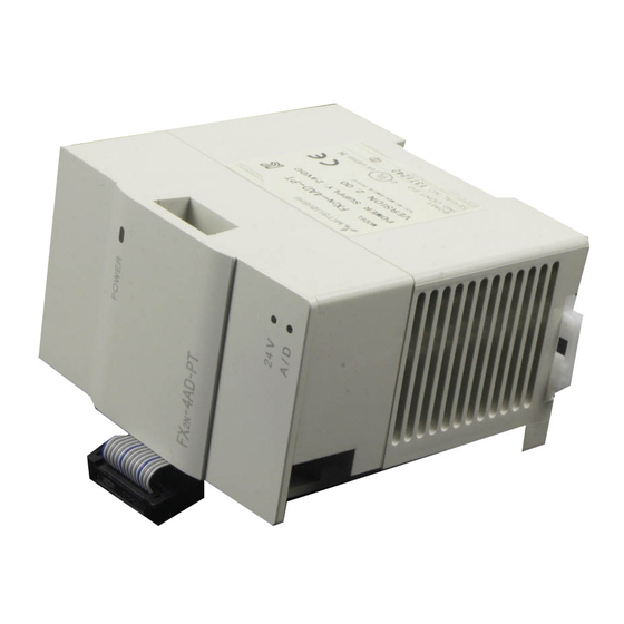
-4AD-PT analog block amplifies the input from four platinum temperature sensors (PT 100, 3 wire, 100 Ω)
The FX
2N
and converts the data into 12 bit reading's stored in the Main Processing Unit (MPU). Both Centigrade (°C) and
Fahrenheit (°F) can be read. Reading resolution is 0.2°C to 0.3°C / 0.36°F to 0.54°F.
•
All data transfers and parameter setups are adjusted through software control of the FX
TO/FROM applied instructions in the FX
•
The FX
-4AD-PT occupies 8 points of I/O on the FX
2N
puts or outputs. The FX
1.1 EXTERNAL DIMENSIONS
2
1
PT100
shielded CH1
1
PT100
CH4
shielded
DC24V±10% 50mA 2
4
3
Class 3
PC
Grounding
(100 Wor less)
Extension cable
PC.
2N
-4AD-PT draws 30mA from the 5V rail of the MPU or powered extension unit.
2N
Weight : Approx. 0.3 kg (0.66 lbs)
TERMINAL LAYOUTS
5V
4.7K
4.7K
L+
100K
L-
100K
I-
FG
AG
L+
L-
5V
I-
FG
AG
24+
+15V
DC/DC
AG
converter
24-
-15V
FX
-4AD-PT
2N
FX
-4AD-PT SPECIAL FUNCTION BLOCK
2N
INTRODUCTION
expansion bus. The 8 points can be allocated from either in-
2N
The cable of the PT 100 sensor or a twisted shielded
cable should be used for the analog input cable. This
analog input cable should be wired separately from
power lines or any other lines which may induce noise.
The three wire method improves the accuracy of the
sensors by compensating voltage drops.
If there is electrical noise, connect the frame ground
terminal (FG) with the ground terminal.
Connect the ground terminal on the FX
with the grounded terminal on the base unit. Use
class 3 grounding on the base unit, if grounding is
possible.
Either an external or the 24V built-in supply in the
programmable controller may be used.
For additional data regarding EMC considerations
please see section 7.0.
USER'S GUIDE
JY992D65601A
SERIES HARDWARE MANUAL .
2N
-4AD-PT ; by use of the
2N
Dimensions : mm (inches)
-4AD-PT unit
2N
Advertisement
Table of Contents

Related Manuals for Mitsubishi FX2N-4AD-PT


Summary of Contents for Mitsubishi FX2N-4AD-PT
- Page 1 -4AD-PT SPECIAL FUNCTION BLOCK USER’S GUIDE JY992D65601A This manual contains text, diagrams and explanations which will guide the reader in the correct installation and operation of the FX -4AD-PT special function block and should be read and understood before attempting to install or use the unit.
-
Page 2: Installation Notes And Usage
2.1 Using crimp terminations • Use crimp terminations of the type indicated on the left. • Secure the termination using a tightening torque of between 5 and 8 kg⋅cm. • Wire only to the module terminals discussed in this manual. Leave all others vacant. - Page 3 3.4 Buffer memory assignment The FX -4AD-PT communicates with the CONTENTS programmable controller through use of buffer CH1 to CH4 Averaged temperature reading to be memories. *#1-#4 averaged (1 to 4,096) Default = 8 BFMs (buffer memories) #21 to #27 and #31 are #5-#8 reserved.
-
Page 4: System Block Diagram
SYSTEM BLOCK DIAGRAM POWER 5V Power Gain and Supply offset values are stored in Buffer Command EEPROM Memory information Analog Input write and Photocoupler data status read FROM Converted data series System converter Control signals Multiplexer DC24V ±15V Power Source Cyclic switching DC/DC converter... -
Page 5: Emc Considerations
Electromagnetic compatibility or EMC must be considered before using the FX -4AD-PT. Mitsubishi recommend that the PT 100 sensors used, should be fitted with a form of seild or screening as protection against EMC noise. If some form of cable protection is used, the “Shield” must be terminated at the terminals as shown in section 2.0. - Page 6 -4AD-PT please consult the nearest Mitsubishi Electric distributor. • Under no circumstances will Mitsubishi Electric be liable or responsible for any consequential damage that may arise as a result of the installation or use of this equipment. • All examples and diagrams shown in this manual are intended only as an aid to understanding the text, not to guarantee operation.
- Page 7 2.1 Using crimp terminations 3.4 Buffer memory assignment The FX -4AD-PT communicates with the • CONTENTS Use crimp terminations of the type indicated on the left. programmable controller through use of buffer • CH1 to CH4 Averaged temperature reading to be memories.
- Page 8 Manual revision (BFM #5 to #8) → (D0 to D3) Mitsubishi recommend that the PT 100 sensors used, should be fitted with a form of seild or screening as protection FNC78 Transfer the averaged temperature value in °C to the data...
Need help?
Do you have a question about the FX2N-4AD-PT and is the answer not in the manual?
Questions and answers