Sign In
Upload
Manuals
Brands
Mitsubishi Manuals
Controller
FX2N-16CCL-M
Mitsubishi FX2N-16CCL-M Manuals
Manuals and User Guides for Mitsubishi FX2N-16CCL-M. We have
2
Mitsubishi FX2N-16CCL-M manuals available for free PDF download: User Manual, Hardware Manual
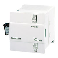
Mitsubishi FX2N-16CCL-M User Manual (194 pages)
CC-Link Master Module
Brand:
Mitsubishi
| Category:
Controller
| Size: 1.39 MB
Table of Contents
Table of Contents
9
1 Introduction
13
Associated Manuals
13
General Names and Abbreviations
14
2 Overview
15
Overview of CC-Link System
15
Overview of CC-Link Master Block FX -16CCL-M
15
Characteristics
16
Major Differences from A/Qna/Q Series
20
3 System Configuration
21
Total Configuration
21
Applicable PLC
22
Configuration Example
23
Example of Maximum Configuration, When Using a FX PLC
23
Scan Time of PLC and Connection of Two or more Master Blocks
24
Example of Connection of Two or more FX Series Plcs
25
Example of Connection to the CC-Link System for the A/Qna/Q Series
26
Number of Occupied Stations and Station Numbers as Well as Number of Modules and Number of Stations
27
System Equipment List
28
Precautions When Configuring the System
31
Wiring of Power Supply
31
Wiring of Remote I/O Modules
32
4 Specification
35
External Dimensions / Part Names
35
Power Supply Specifications
35
General Specification
35
Performance Specification
36
Maximum Transmission Distance
38
Dedicated CC-Link Cable
39
Buffer Memory
40
Buffer Memory List
41
Parameter Information Area
41
I/O Signals to PLC
46
I/O Signal Details
49
Master Block Control Signals
56
Remote Input (RX)
57
Remote Output (RY)
59
Remote Register (Rww) Master Station --> Remote Device Station
61
Remote Register (Rwr) Master Station <-- Remote Device Station
63
Link Special Relay (SB) and Link Special Register (SW)
65
5 Functions
67
Function List
67
Communication between Master Station and Remote I/O Stations
68
Communication between Master Station and Remote Device Stations
70
Communication in Compound System
75
Reserved Station Function
80
Error Invalid Station Function
81
Data Link Status Setting against Error in Master Station PLC
82
Setting of Input Data Status from Data Link Faulty Station
83
Module Reset Function from Sequence Program
84
Data Link Stop/Restart
85
RAS Function
86
Automatic Return Function
86
Slave Station Cutoff Function
86
Station Number Overlap Check Function
87
Temporary Error Invalid Station Specification Function
88
I/O Status When Temporary Error Invalid Stations Are Specified
88
Link Special Relays and Registers (SB and SW) Related to Temporary Error Invalid Station Specification Function
88
Temporary Error Invalid Station Specification Procedure
90
6 Data Link Processing Time
91
Status of each Station When an Error Has Occurred
91
Link Scan Time
93
Transmission Delay Time
94
Master Station ↔ Remote I/O Station
94
Master Station ↔ Remote Device Station
95
7 Parameter Setting
97
Procedure from Parameter Setting to Data Link Startup
97
Relationship Among Buffer Memory, EEPROM and Internal Memory
97
Procedure from Parameter Setting to Data Link Startup
99
Parameter Setting Items
100
Setting from Sequence Program
101
Setting and Operation Using the Buffer Memory
101
Parameter Registration Procedure to the EEPROM and Operation Based on Parameters Registered in the EEPROM
103
Program Example
106
8 Data Link Procedure
111
Data Link Procedure
113
Name of each Part and Settings
114
Master Block Status Check (Hardware Test)
118
Module Wiring with Dedicated CC-Link Cables
119
T-Shaped Branch Connection Using Dedicated CC-Link Cables
120
System Configuration with T-Shaped Branch Connection
120
T-Shaped Branch Communication Specification List
121
Switch Settings
122
Station Number Setting (Master Station, Remote I/O Stations and Remote Device Stations)
122
Mode Setting
124
Transmission Speed Setting
124
Condition Setting
124
Connection Status Check (Line Test)
125
Check of Connection Status and Communication Status with Remote Stations (Line Test 1)
125
Check of Communication Status with Specific Remote Station (Line Test 2)
126
Parameter Check (Parameter Verification Test)
127
9 Programming
129
Precautions in Programming
129
Programming Procedure
131
Communication between Master Station and Remote I/O Stations
131
Communication between Master Station and Remote Device Stations
132
Communication in Compound System
133
Link Special Relay/Register (SB/SW)
134
Link Special Relay (SB) List
134
Link Special Register (SW)
138
10 Communication between Master Station and Remote I/O Stations
145
System Configuration
145
Setting of Master Station
145
Setting of Remote I/O Station
146
Creating a Program
147
Program for Parameters
147
Program for Communication
149
Execution of Data Link
151
Confirmation of Operation by LED Indication
151
Confirmation of Operation by Program
152
11 Communication between Master Station and Remote Device Stations
153
System Configuration
153
Setting of Master Station
153
Setting of Remote Device Station
154
Creating a Program
155
Program for Parameters
155
Program for Communication
157
Execution of Data Link
161
Confirmation of Operation by LED Indication
161
Confirmation of Operation by Program
162
12 Communication in Compound System
163
System Configuration
163
Setting of Master Station
163
Setting of Remote I/O Station
164
Setting of Remote Device Station
164
Creating a Program
165
Program for Parameters
165
Program for Communication
167
Execution of Data Link
170
Confirmation of Operation by LED Indication
170
Confirmation of Operation by Program
171
13 Troubleshooting
173
Verification When Trouble Occurs
174
Troubleshooting When ERR LED Is Flashing in Master Station
177
Error Codes
179
LED Indication Status
183
When Data Link Is Normal
183
When a Cable Is Broken
183
When a Cable Is Short-Circuited
184
When Link Is Stopped in the Master Station
184
When Power Supply to a Remote I/O Station Is Turned off
185
When Power Supply to a Remote Device Station Is Turned off
185
When a Station Number Overlaps
186
When the Transmission Speed Is Incorrectly Set
186
When the Switch Setting Is Changed During Data Link
187
10When Data Link Is Started with a Switch Set Outside the Allowable Range
187
11When a Remote I/O Station Is Not Set in the Parameter (and Set as a Reserved Station)
188
12When a Remote Device Station Is Not Set in the Parameter (and Set as a Reserved Station)
188
14 Appendix
189
Advertisement
Mitsubishi FX2N-16CCL-M Hardware Manual (8 pages)
Brand:
Mitsubishi
| Category:
Terminal Block
| Size: 0.23 MB
Table of Contents
Installation and Wiring
4
Installation Precautions
4
Wiring Precautions
4
General Specification
5
Advertisement
Related Products
Mitsubishi FX2N-16LNK-M
Mitsubishi FX2N-10GM
Mitsubishi MELSEC-F FX2N-16
Mitsubishi MELSEC-F FX2N-128
Mitsubishi FX2N-485-BD
Mitsubishi FX2N-422-BD
Mitsubishi FX2N-64CL-M
Mitsubishi FX2NC DS Series
Mitsubishi MELSEC-F FX2N-64
Mitsubishi MELSEC-F FX2N-32
Mitsubishi Categories
Air Conditioner
Controller
Projector
Automobile
Engine
More Mitsubishi Manuals
Login
Sign In
OR
Sign in with Facebook
Sign in with Google
Upload manual
Upload from disk
Upload from URL