Table of Contents
Advertisement
Advertisement
Table of Contents

Related Manuals for Mitsubishi FX2N-32CCL


Summary of Contents for Mitsubishi FX2N-32CCL
- Page 1 USER’S MANUAL CC-Link INTERFACE BLOCK FX -32CCL...
- Page 2 • If in doubt about the operation or use of the FX -32CCL CC-Link Interface Block please consult the nearest Mitsubishi Electric distributor. • This manual is subject to change without notice.
- Page 3 -32CCL CC-Link Interface Block -32CCL CC-Link INTERFACE BLOCK Manual number : JY992D71801 USER’S MANUAL Manual revision : Date April 2003...
- Page 4 -32CCL CC-Link Interface Block Guidelines for the safety of the user and protection of the FX -32CCL CC-Link Interface Block This manual provides information for the installation and use of the FX -32CCL CC-Link Interface Block. The manual has been written to be used by trained and competent personnel. The definition of such a person or persons is as follows: a) Any engineer who is responsible for the planning, design and construction of automatic equipment using the product associated with this manual, should be of a competent nature, trained and qualified...
- Page 5 -32CCL CC-Link Interface Block Hardware warnings 1 ) Indicates that the identified danger WILL cause physical and property damage. 2 ) Indicates that the identified danger POSSIBLY cause physical and property damage. 3 ) Indicates a point of further interest or further explanation. Software warnings 1 ) Indicates special care must be taken when using this element of software.
- Page 6 • All examples and diagrams shown in this manual are intended only as an aid to understanding the text, not to guarantee operation. Mitsubishi Electric will accept no responsibility for actual use of the product based on these illustrative examples.
-
Page 7: Table Of Contents
-32CCL CC-Link Interface Block Contents CONTENTS 1. Introduction ....................1-1 1.1 Outline of product ...................... 1-1 1.2 Connection to CC-Link ....................1-3 1.3 System configuration of entire CC-Link ..............1-4 2. Product Specifications ................2-1 2.1 Outside dimensions and nomenclature ..............2-2 2.2 General specifications and performance specifications .......... - Page 8 Contents -32CCL CC-Link Interface Block 6.3 Program in master PC ....................6-5 6.4 Program in FX PC ....................6-11...
-
Page 9: Introduction
-32CCL CC-Link Interface Block Introduction 1 Introduction The CC-Link interface block FX -32CCL is an interface block which connects the FX PC to the CC-Link. Outline of product Applicable PC The FX -32CCL can be connected as a special extension block of the FX Series micro PC. - Page 10 -32CCL CC-Link Interface Block Introduction 1 Transmission speed Transmission distance 10 Mbps : 100 m 5 Mbps : 150 m 2.5 Mbps : 200 m 625 kbps : 600 m 156 kbps : 1,200 m Detailed specifications conform to the CC-Link system common specifications. Number of remote points The number of remote I/O points in one station is 32 input points and 32 output points.
-
Page 11: Connection To Cc-Link
-32CCL CC-Link Interface Block Introduction 1 Connection to CC-Link The FX PC connected with the interface block FX -32CCL functions as a remote device station in the CC- Link system. One to four FX -32CCL units can be used at a time, and station Nos. not assigned to these FX -32CCL units should be assigned to other remote device stations, remote I/O stations and local stations. -
Page 12: System Configuration Of Entire Cc-Link
-32CCL CC-Link Interface Block Introduction 1 System configuration of entire CC-Link The figure below shows the system configuration of the entire CC-Link. For the details, refer to the user manual of the master unit in the CC-Link system. Up to 26 units Master station Local station Local station... -
Page 13: Product Specifications
-32CCL CC-Link Interface Block Specifications 2 Product Specifications Cautions on design • For the status of each station in the case in which the PC CPU stops its operation or communica- tion error has occurred in the data link, read thoroughly the contents of "5. Data Link Processing Time"... -
Page 14: Outside Dimensions And Nomenclature
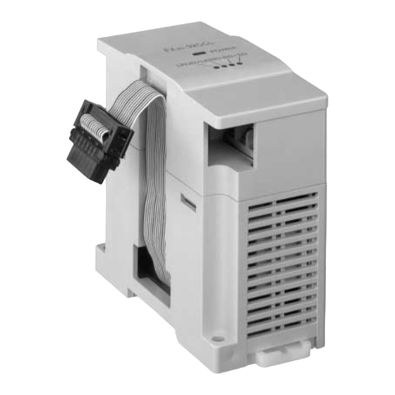
Accessories: Special block No. label. External 24 VDC 43(1.69) 87(3.42) M3(0.12) ground terminal terminal screw Station No. set switch Extension cable Number of occupied stations FX2N-32CCL set switch DIN rail POWER Next step 35mm(1.38) LRUN LERR extension mounting connector bezel 2-φ4.5(0.18) Baud rate... -
Page 15: General Specifications And Performance Specifications
-32CCL CC-Link Interface Block Specifications 2 General specifications and performance specifications General specifications Dielectric strength:500 VAC for 1 min (between external terminals as a whole and ground terminal) Other specifications are equivalent to those of the PC basic unit. Performance specifications Item Specifications of FX -32CCL... - Page 16 -32CCL CC-Link Interface Block Specifications 2 Item Specifications of FX -32CCL 156 kbps, 625 kbps, 2.5 Mbps, 5 Mbps, 10 Mbps (set by rotary switch) B RATE 0: 156 kbps 1: 625 kbps 2: 2.5 Mbps Transmission speed 3: 5 Mbps 4: 10 Mbps 5 to 9: Setting error It varies depending on the transmission speed.
- Page 17 -32CCL CC-Link Interface Block Specifications 2 Item Specifications of FX -32CCL LEDs (POWER, L RUN, L ERR, RD, SD) Operation indication Number of occupied Eight I/O points (including input and output) of FX PC I/O points , FX , FX Series PC Applicable PC Communication is performed from the FX PC via the buffer memory using FROM/TO...
- Page 18 -32CCL CC-Link Interface Block Specifications 2 Memo...
-
Page 19: Connection And Wiring
-32CCL CC-Link Interface Block Connection and Wiring 3 Connection and Wiring Connection to PC Connection of extension cable The FX -32CCL can be connected directly to the FX PC main unit or connected on the right side of an other extension block or extension unit. Up to eight special units/blocks can be connected, and the unit No. -
Page 20: Wiring Of Power Supply
-32CCL CC-Link Interface Block Connection and Wiring 3 Wiring of power supply Wiring Service power supply for sensor Grounding resistor 100 Ω or less (class 3) 24 VDC+/-10%, 50 mA 24 VDC service power supply for PC can be used PC main unit -32CCL instead. -
Page 21: Wiring Of Cc-Link
A lum inum tape C ross section G round cable Y ellow O utside dim ensions 7m m 65k g/k m A pproxim ate w eight About the shielded twisted pair cables, consult the nearest MITSUBISHI ELECTRIC CORPORATION service center. - Page 22 -32CCL CC-Link Interface Block Connection and Wiring 3 Wiring of twisted pair cable Wire the FX -32CCL and the CC-Link using shielded twisted pair cables as shown in the figure below. M aster R em ote I/O -32C C L unit unit T erm inal...
-
Page 23: Setting Of Remote Device Stations
-32CCL CC-Link Interface Block Setting of Remote Device Stations 4 Setting of Remote Device Stations Setting of station Nos., number of stations and transmission speed Setting the rotary switch The station No., the number of stations and the transmission speed can be set using rotary switches provided inside the panel cover of the FX -32CCL. - Page 24 -32CCL CC-Link Interface Block Setting of Remote Device Stations 4 3 ) Baud rate (transmission speed): 156 kbps, 625 kbps, 2.5 Mbps, 5 Mbps, 10 Mbps Numerics 0 to 4 correspond to 156 kbps to10 B RATE Mbps respectively. 0: 156 kbps 3: 5 Mbps 1: 625 kbps 4: 10 Mbps...
-
Page 25: List Of Number Of Remote Points And Remote Nos
-32CCL CC-Link Interface Block Setting of Remote Device Stations 4 List of number of remote points and remote Nos. In the FX -32CCL, the number of remote points vary depending on the selected number of stations (1 to 4). • Thirty-two remote input points and 32 remote output points are available in one station. - Page 26 -32CCL CC-Link Interface Block Setting of Remote Device Stations 4 Memo...
-
Page 27: Assignment Of Buffer Memory (Bfm)
-32CCL CC-Link Interface Block Assignment of Buffer Memory (BFM) 5 Assignment of Buffer Memory (BFM) Outline of data communication The interface block FX -32CCL transfers data between the master station in the CC-Link via the built-in buffer memory (BFM) backed up by the 16-bit RAM memory. This buffer memory consists of memory dedi- cated to write and memory dedicated to read. -
Page 28: Bfm Dedicated To Read
-32CCL CC-Link Interface Block Assignment of Buffer Memory (BFM) 5 BFM dedicated to read → → → → Master station Buffer memory dedicated to read In this buffer memory, data written from the master station and the system information on the FX -32CCL are saved. - Page 29 -32CCL CC-Link Interface Block Assignment of Buffer Memory (BFM) 5 Details of buffer memory [BFM #0 to #7 (remote output RY00 to RY7F)] • Sixteen remote output points RYoF to RYo0 are assigned for b15 to b0 of each buffer memory consist- ing of 16 bits.
- Page 30 -32CCL CC-Link Interface Block Assignment of Buffer Memory (BFM) 5 Example in which the ON/OFF status of multiple BFM points are read to the FX PC • By changing the number of transfer points of FNC78 K4M0 FROM instruction within the range of K1 to K8, FROM Number of BFM #0 to BFM #7 can be read at a time to the...
- Page 31 -32CCL CC-Link Interface Block Assignment of Buffer Memory (BFM) 5 [BFM #8 to #23 (remote register RWw0 to RWwF)] • To each buffer memory No., a remote register No. RWw0 to RWwF is assigned. The information saved in the buffer memory indicates the contents of the remote register written from the master unit to the FX -32CCL.
- Page 32 -32CCL CC-Link Interface Block Assignment of Buffer Memory (BFM) 5 [BFM #24 (set value of baud rate)] The setting of the baud rate (transmission speed) set switch provided in the FX -32CCL is saved as a numeric of 0 to 4. The saved value is determined when the power of the FX PC is turned on.
- Page 33 -32CCL CC-Link Interface Block Assignment of Buffer Memory (BFM) 5 [BFM #28 (set value of number of occupied stations)] The setting of the number of occupied stations set switch provided in the FX -32CCL is saved as a numeric of 0 to 3. 0: 1 station 1: 2 stations 2: 3 stations...
-
Page 34: Bfm Dedicated To Write
-32CCL CC-Link Interface Block Assignment of Buffer Memory (BFM) 5 BFM dedicated to write FX → → → → master station Buffer memory dedicated to write In this buffer memory, the contents written from the FX PC to the master station are saved. The FX PC writes the contents of bit devices and data (word) devices of the PC using TO instructions. - Page 35 -32CCL CC-Link Interface Block Assignment of Buffer Memory (BFM) 5 Details of buffer memory [BFM #0 to #7 (remote input RX00 to RX7F)] • Sixteen remote input points RXoF to RXo0 are assigned for b15 to b0 of each buffer memory consisting of 16 bits.
- Page 36 -32CCL CC-Link Interface Block Assignment of Buffer Memory (BFM) 5 Example in which the ON/OFF status of the FX PC is written to multiple BFM points • By changing the number of transfer M100 (RX00) points of TO instruction within the Program range of K1 to K8, the contents of M101...
- Page 37 -32CCL CC-Link Interface Block Assignment of Buffer Memory (BFM) 5 [BFM #8 to #23 (remote register RWr0 to RWrF)] • To each buffer memory No., a remote register No. RWr0 to RWrF is assigned. The information to be written to the master unit should be preliminarily transferred from the FX PC to this buffer memory.
-
Page 38: System Area Of Remote I/O
-32CCL CC-Link Interface Block Assignment of Buffer Memory (BFM) 5 System area of remote I/O As to the number of remote I/O points (RX00 to RX7F/RY00 to RY7F) in the FX -32CCL, the range and the number of points vary depending on the selected number of stations (1 to 4). The upper 16 points of the final station are occupied by the CC-Link system as the system area, so cannot be used as the user area. - Page 39 -32CCL CC-Link Interface Block Assignment of Buffer Memory (BFM) 5 5-13...
-
Page 40: Contents Of Errors
-32CCL CC-Link Interface Block Assignment of Buffer Memory (BFM) 5 Contents of errors The table below shows the contents of errors indicated by LEDs provided in the FX -32CCL. The causes of an error can be detected based on the contents of the error saved in the buffer memory dedi- cated to read BFM #29 and the status of the LED. -
Page 41: Programming Examples
-32CCL CC-Link Interface Block Programming Examples 6 Programming Examples System configuration A sample program is explained in the system configuration shown below. M a ster R e m o te de vice R e m o te de vice statio n statio n statio n (sta tion N o . - Page 42 -32CCL CC-Link Interface Block Programming Examples 6 Preparation 1 ) Set the station No. set switch, the mode set switch, the transmission set switch and the condition set switch provided on the master unit. ( User’s manual of master unit) 2 ) Set the station No.
-
Page 43: Flow Of Communication Data
-32CCL CC-Link Interface Block Programming Examples 6 Flow of communication data Remote input (RX), remote output (RY) In a sample program, communication is performed between remote inputs and remote outputs as shown in the figure below. Master station Master PC (station No. - Page 44 -32CCL CC-Link Interface Block Programming Examples 6 Remote register (RWr, RWw) In a sample program, communication is performed in remote registers as shown in the figure below. Master station (station No. 0) Master PC Remote device station (station No. 1) -32CCL FX PC Remote register (RWr)
-
Page 45: Program In Master Pc
-32CCL CC-Link Interface Block Programming Examples 6 Program in master PC When the PC CPU starts to run, data linking is automatically started by the program shown below. During debugging Parameter setting X0000 X000F M300 Unit error Unit ready M300 M301 M301 Number of connected units... - Page 46 -32CCL CC-Link Interface Block Programming Examples 6 M 9038 Instruction S E T of refresh Initial pu lse D ata link by param eter of buffer m em ory X 0000 X 000F P LS M 302 M 302 S E T M 303 M 303 D ata link startup request by param eter of...
- Page 47 -32CCL CC-Link Interface Block Programming Examples 6 P a ra m e te r reg istration to R e gis tra tio n E E P R O M X 0000 X 000F co m m a n d P LS M 304 M 304 S E T...
- Page 48 -32CCL CC-Link Interface Block Programming Examples 6 During operation M 9038 Instruction S E T of refresh In itia l p ulse D ata link by param eter of X 0000 X 000F E E P R O M P LS M 300 U n it e rro r U n it rea d y M 300...
- Page 49 -32CCL CC-Link Interface Block Programming Examples 6 Program for communication with remote device station X0000 X000F X0001 Data link status (SW0080) of FROM H0000 H0680 K1M401 remote device station is read. Unit error Unit ready Data link M401 status -32CCL (station No. 1) CALL Data link being executed Link normal (station No.
- Page 50 -32CCL CC-Link Interface Block Programming Examples 6 Communication with FX 32CCL (station No. 5) M9036 Read of remote input FROM H0000 H00E8 K4M900 (RXBF to RX80) → M963 to M900 to E8 Always Write of remote output H0000 H0168 K4M1000 M1063 to M1000 →16B to 168 (RYBF to RY80)
-
Page 51: Program In Fx Pc
-32CCL CC-Link Interface Block Programming Examples 6 Program in FX PC When the PC starts to run, data linking is automatically started by the program shown below. Communication program in station No. 1 R ead of com m unication status M 8000 R ead of com m unication status F N C 78... - Page 52 -32CCL CC-Link Interface Block Programming Examples 6 Read of remote output and register Read of remote output FNC78 BFM #7 to #0 (RY7F to RY00) → M427 to M300 K4M300 FROM Link being executed Read of remote register FNC78 BFM #23 to #8 (RWwF to RWw0) → D65 to D50 FROM M300 (RY00)
- Page 53 -32CCL CC-Link Interface Block Programming Examples 6 Example of communication program in station No. 2 The contents equivalent to those in the station No. 1 described above are to be programmed as a communi- cation status read program. Read of remote output and register Read of remote output FNC78...
- Page 54 -32CCL CC-Link Interface Block Programming Examples 6 Memo 6-14...
- Page 55 -32CCL CC-Link Interface Block...
- Page 56 USER’S MANUAL CC-Link INTERFACE BLOCK FX -32CCL HEAD OFFICE: MITSUBISHI DENKI BLDG MARUNOUCHI TOKYO 100-8310 HIMEJI WORKS: 840, CHIYODA CHO, HIMEJI, JAPAN FX2N-32CCL-U-E MODEL 09R711 MODEL CODE JY992D71801C Effective Apr. 2003 (MEE) Specifications are subject to change without notice.
Need help?
Do you have a question about the FX2N-32CCL and is the answer not in the manual?
Questions and answers