2N Helios IP Vario Installation Manual
Door entry ip intercom
Hide thumbs
Also See for Helios IP Vario:
- Installation manual (70 pages) ,
- Installation manual (61 pages)

Related Manuals for 2N Helios IP Vario


Summary of Contents for 2N Helios IP Vario
- Page 1 ® 2N Helios IP Vario Door Entry IP Intercom Installation Manual Version: www.2n.cz...
- Page 2 2N TELEKOMUNIKACE a.s. administers the FAQ database to help you quickly find information and to answer your questions about 2N products and services. On www. faq.2n.cz you can find information regarding products adjustment and instructions for optimum use and procedures „What to do if...".
- Page 3 The 2N TELEKOMUNIKACE a.s. is the holder of the ISO 9001:2009 certificate. All development, production and distribution processes of the company are managed by this standard and guarantee a high quality, technical level and professional aspect of all our products.
- Page 4 3.3 Display-Equipped Intercom as Viewed by External User 3.4 Intercom Control as Viewed by Internal User 3.5 Maintenance 3.6 Downloads 4. Technical Parameters 5. Supplementary Information 5.1 Troubleshooting 5.2 Directives, Laws and Regulations 5.3 General Instructions and Cautions 2N TELEKOMUNIKACE a.s., www.2n.cz 4/97...
-
Page 5: Product Overview
1. Product Overview Here is what you can find in this section: 1.1 Components and Associated Products 1.2 Terms and Symbols 2N TELEKOMUNIKACE a.s., www.2n.cz 5/97... -
Page 6: Basic Features
Basic Features ® Helios IP Vario is a highly reliable IP door access intercom provided with a lot of useful above-standard functions. Supporting the SIP standard and being compatible ® with the leading IP PBX and telephone suppliers, Helios IP Vario can make use of all VoIP services. -
Page 7: Advantages Of Use
Audio codecs (G.711, G.729, G.722, L16/16kHz) HTTP server for configuration SNTP client for time synchronisation with server RTSP server for video streaming SMTP client for e-mail sending TFTP client for automatic configuration and firmware update 2N TELEKOMUNIKACE a.s., www.2n.cz 7/97... -
Page 8: Components And Associated Products
Part No. 3 buttons 9137131(C)U control of one electric lock possibility of connecting card reader, extenders or information panel or additional switch 2N TELEKOMUNIKACE a.s., www.2n.cz 8/97... - Page 9 Part No. 1 button 9137111(C)KU keypad control of one electric lock possibility of connecting card reader, extenders or information panel or additional switch 2N TELEKOMUNIKACE a.s., www.2n.cz 9/97...
- Page 10 Part No. 6 buttons 9137161(C)U keypad control of one electric lock possibility of connecting card reader, extenders or information panel or additional switch 2N TELEKOMUNIKACE a.s., www.2n.cz 10/97...
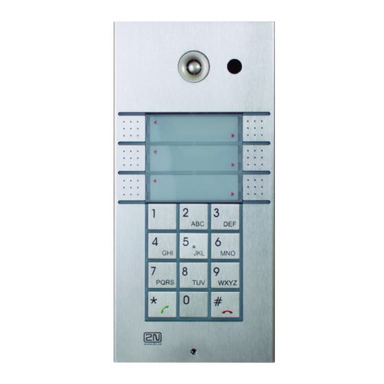
- Page 11 Part No. 6 buttons 9137160(C)KDU graphic display keypad control of one electric lock possibility of connecting card reader, extenders or information panel or additional switch (C) = Integrated camera 2N TELEKOMUNIKACE a.s., www.2n.cz 11/97...
-
Page 12: Extending Modules
Extending Modules Part No. Extending module 9135181E 8 buttons Dimension of the module 100 x 210 x 29 mm Part No. Extending module 9135182E 16 buttons Dimension of the module 100 x 210 x 29 mm 2N TELEKOMUNIKACE a.s., www.2n.cz 12/97... - Page 13 Part No. Info panel 9135310E Backlit panel without buttons; used for insertion of a telephone directory, company logo, house number, etc. 2N TELEKOMUNIKACE a.s., www.2n.cz 13/97...
- Page 14 Info panel – name plate Replacing cover for four name tags. Helps you use a half of the extending module for insertion of a telephone directory, working hours, etc. Part No. 9135302E Spare double-button name plate 2N TELEKOMUNIKACE a.s., www.2n.cz 14/97...
- Page 15 All units can be surface mounted without needing any additional accessories. To make them even more robust and resistant, use a Vandal Resistant mask. Caution For flush or outdoor mounting you need to use the accessories; see the Mounting Accessories subsection. 2N TELEKOMUNIKACE a.s., www.2n.cz 15/97...
-
Page 16: Mounting Accessories
Wall hole: (110 × 220 × 50) ±5 mm Part No. 9135361E Wall mounting boxwith 1-module roof Roof dimensions: (129 × 240 × 41) mm (W × H × D) Wall hole: (110 × 220 × 50) ±5 mm 2N TELEKOMUNIKACE a.s., www.2n.cz 16/97... - Page 17 Dimensions: (203 × 218 × 60) mm (W × H × D) Part No. 9135352E Wall mounting boxwith 2-module frame Dimensions: (225 × 235 × 46) mm (W × H × D) Wall hole: (210 × 220 × 50) ±5 mm 2N TELEKOMUNIKACE a.s., www.2n.cz 17/97...
- Page 18 The box ® with frame (without roof) allows for installation of Helios IP Vario in indoor applications so that the unit does not practically stick out (up to 1 mm).
-
Page 19: Internal Units
On the panel’s display not only can you find out who is at the door, but also start a conversation with the visitor, open the lock or turn on the light in the entrance hall. 2N TELEKOMUNIKACE a.s., www.2n.cz 19/97... -
Page 20: Voip Telephones
IP network. Touchscreen and keyboard control. Part No. 91378358 Grandstream GXV3275 VoIP telephone GXV3275 is the successor to the popular GXV3175 model, which allows comfortable video calls in the IP network. Touchscreen control. 2N TELEKOMUNIKACE a.s., www.2n.cz 20/97... -
Page 21: Electric Locks
Part No. 932091E BEFO 11211MB with mechanical blocking 12V/230mA DC low consumption Enables mechanically close or open the lock. When opened, the lock is open all the time. When closed, it behaves as standart electrical lock. 2N TELEKOMUNIKACE a.s., www.2n.cz 21/97... - Page 22 The failsafe lock is closed when electricity is switched on. When electricity is interrupted, the lock is opened. It contains a built-in contact to indicate whether the door is open or closed. FAQ: Electric locks - Difference between locks in 2N Helios IP accesories 2N TELEKOMUNIKACE a.s., www.2n.cz 22/97...
-
Page 23: Power Supply
PoE switch is not available. Part No. 91341481E Stabilised 12 V / 2 A power supply needs to be used when no PoE is available. Part No. 932928 For external power supply of the lock with 12V AC voltage. 2N TELEKOMUNIKACE a.s., www.2n.cz 23/97... -
Page 24: Additional Modules
Card reader 125kHz Internal RFID card reader for installation in the basic ® module of the Helios IP Vario intercom. Allows the use of EM4100, EM4102 and HID Proximity cards. Another two switches, two logical inputs and a Wiegand interface are available. It is compatible with ®... - Page 25 Helios IP Wiegand Isolator is designed for galvanic isolation of two devices separately power supplied and interconnected via the Wiegand bus. The ® 2N Helios IP Wiegand Isolator protects the interconnected devices against communication errors and/or damage. Part No. 9137410E...
- Page 26 (suitable for Internal RFID card reader or Security relay) A button for connection to a logic input for opening a door inside a building. Part No. 9159012 Magnetic door contact (suitable for Internal RFID card reader) 2N TELEKOMUNIKACE a.s., www.2n.cz 26/97...
- Page 27 2N 2Wire unit at each end of the cable and a power source ® connected to at least one of these units. The 2N 2Wire unit then provides power not only to the second converter, but also to all other connected IP end devices.
- Page 28 USB interface. Suitable for system administration and adding 13.56MHz and 125kHz cards using a web ® interface or the Access Commander application. It reads the same types of cards as card readers in 2N Helios IP intercoms. 2N TELEKOMUNIKACE a.s., www.2n.cz 28/97...
- Page 29 Part No. 9159052 ® Power supply for 2N Induction Loop External power supply for the induction loop. Input 230V AC Output 12V DC Part No.
-
Page 30: Terms And Symbols
Warning Always abide by this information to prevent damage to the device. Caution Important information for system functionality. Useful information for quick and efficient functionality. Note Routines or advice for efficient use of the device. 2N TELEKOMUNIKACE a.s., www.2n.cz 30/97... -
Page 31: Description And Installation
2. Description and Installation Here is what you can find in this section: 2.1 Before You Start 2.2 Mechanical Installation 2.3 Electric Installation 2.4 Completion 2.5 Extending Module Connection 2N TELEKOMUNIKACE a.s., www.2n.cz 31/97... -
Page 32: Product Completeness Check
Product Completeness Check ® Before you start please check whether the contents of the package of your new 2N Helios IP Vario complies with the following list. ® 1× 2N Helios IP Vario 1× spare seal 1× drilling template 1× hexagonal wrench 1×... -
Page 33: Mechanical Installation
An overview of the installation types and the list of the required components are provided in the table below. Installation Symbol What you need for installation type Indoor, on ® Helios IP Vario only surface Indoor, ® Helios IP Vario flush mounting... - Page 34 Installation Symbol What you need for installation type With ® Helios IP Vario increased resistance Vandal resistant mask with box, version according to the assembly Indoor Indoor areas with a low relative air humidity application value (e.g., hallways, offices and other heated rooms).
-
Page 35: Surface Mounting
Insert the included dowels in the wall holes. ® 2. Use the hexagon key wrench included in the supply and remove the 2N Helios IP Vario metal cover. Remove the screw in the lower part of the metal cover and fold out the cover. - Page 36 Never remove the main board or camera electronics from under the ® lower cover while installing Helios IP Vario . Do not disconnect the camera flat cable from the main board. Do not bend and press upon the flat cable either.
- Page 37 9. Connect the cables as described in subsection 2.4, Mounting – Electrical Installation. Make sure that the cables are not squeezed while installing the plastic cover. For the correct cable installation. ® 10.Remove the protective foil from the display (for display-equipped 2N Helios IP Vario versions only).
-
Page 38: Outdoor Installation Rules
19. Check whether a silicone seal is inserted in the top groove of the plastic cover. A spare seal package is included. 20. Close the metal cover and fix it with screws. Outdoor Installation Rules Always connect button backlighting – it is used for heating. 2N TELEKOMUNIKACE a.s., www.2n.cz 38/97... -
Page 39: Name Tag Material And Printing
Name Tag Material and Printing ® Each Helios IP Vario package includes a sheet of transparent foil for laser printing. Cut the printed foil into pieces and insert the labels in the name plates. Do not use paper to avoid water in-leak and paper damage. -
Page 40: Electric Installation
Mozilla Firefox. Video Tutorial: Door communication system 2N® Helios IP Vario - Electrical Installation Description of Printed Circuit Board Connectors In figure bellow you can see the location of the printed circuit board (PCB) connectors. - Page 41 Description of Connectors, PCB Version 530v2 Description of Connectors, PCB Versions 535v1, 535v2 2N TELEKOMUNIKACE a.s., www.2n.cz 41/97...
-
Page 42: Terminal Block X2 Connection
12 V / 2 A DC power supply if no PoE power supply is available. ® The terminal block is included in the package. To adjust an already installed 2N Helios IP Vario , disconnect it IP from the power supply. Then pull to remove the terminal block from the printed circuit board. -
Page 43: Ethernet Connection
Figure 2.7. Ethernet Connection For the connections and meanings of the wires see the table below. Join UTP cable ® wires 4 (blue) and 5 (white-blue) and attach them under terminal 6 on 2N Helios IP ® Vario... -
Page 44: Electric Lock Connection
Terminal Block Connection for Electric Lock ® Terminals 3 and 4 are connected to a relay on the Helios IP Vario board. The relay terminals may act as normally open or normally closed contacts. Configuration is performed through the configuration connector X1 as described in the Configuration Connector Connection subsection. -
Page 45: External Power Supply Connection
External Power Supply Connection If the Ethernet network is not equipped with the PoE technology, you have two ® alternative options how to supply power to Helios IP Vario ® Using a PoE injector, Part No. 91378100. Helios IP Vario is then powered through an Ethernet cable as shown in Tab. -
Page 46: Display Connector
Connection of Configuration Connector Jumpers Display Connector The display connector includes the name plate backlighting ON/OFF switching pins ® Helios IP Vario resetting pins. The remaining pins are intended for display connection. Resetting procedure ® Switch Helios IP Vario off. - Page 47 ® Switch Helios IP Vario on and wait for the acoustic start signalling. ® Switch Helios IP Vario off. Remove the jumper from the resetting (default setting) position (put the display switch into the NORMAL position in the display-equipped models with 535v1 and 535v2 board versions).
-
Page 48: Card Reader Connection
® To reset the default values of a display-equipped Helios IP Vario , put the switch in the display right-hand bottom corner in position F_RES. This applies to modules with board versions 535v1 and 535v2 only. For 535v5 versions, use a jumper at connector X13. -
Page 49: Card Reader Mounting
® Use the enclosed screws to fix the reader module to the 2N Helios IP Vario plastic base. Connect the wires for the reader module interface(s) if necessary. - Page 50 At the marked point push the nut genthly sliding it downwards. Insert a sufficiently long M3 screw, e.g. Push the screw down to make a gap for the crimp eye. At the marked point insert the crimped cable. Assemble the set and ground the cable. 2N TELEKOMUNIKACE a.s., www.2n.cz 50/97...
-
Page 51: Available Switches
Passive switch: NO and NC contacts, up to 30 V / 1 A AC/DC RFID Card (Card Reader Reader) 125 kHz (Part No. Relay 2 Passive switch: NO and NC contacts, up to 30 V / 1 A AC/DC 9137430 (Card Reader) 2N TELEKOMUNIKACE a.s., www.2n.cz 51/97... -
Page 52: Most Frequent Mounting Errors
2.4 Completion ® Remember to seal the Helios IP Vario cable passage hole properly to avoid moisture in-leak and damage to electronics due to condensation. ® Make sure that the wires inside Helios IP Vario are not squeezed and insert the plastic top cover (a transparent plastic mould) carefully making its contacts plug into the electronics board connectors. - Page 53 2N TELEKOMUNIKACE a.s., www.2n.cz 53/97...
- Page 54 2N TELEKOMUNIKACE a.s., www.2n.cz 54/97...
-
Page 55: Extending Module Connection
2.5 Extending Module Connection ® Helios IP Vario allows to connect following extending modules: Extending button modules Additional Switch Internal RFID Card Reader 125 kHz Security Relay Wiegand Isolator Induction Loop Extending button modules ® Helios IP Vario features an easy installation of extending button modules. -
Page 56: Maximum Count Of Extenders
The basic unit is always on the left. Extenders are chain-connected, i.e. each is linked with its neighbour. The cable cannot be driven through the box interconnecting holes until the boxes have been connected (see subsection 2.3 Mounting – Mechanical Installation). Connection of Two-Button-Row Extending Module 2N TELEKOMUNIKACE a.s., www.2n.cz 56/97... -
Page 57: Button Numbering - Whole-Button Sets
The extending modules must be connected mutually and with the basic unit by means of a formed piece supplied with the extending module!!! Button Numbering Button numbering – one-button with a whole-button set Button numbering – whole-button sets 2N TELEKOMUNIKACE a.s., www.2n.cz 57/97... -
Page 58: Button Numbering - Double-Button Set
Additional Switch ® Additional Switch (Part No. 9137310 E) is used to extend the Helios IP Vario ® door communicator with another switch. Helios IP Vario Additional Switch suitable for e.g. electric door lock or low voltage logical inputs of e.g. gate and barrier control systems. -
Page 59: Specifications
Function: ® ® Helios IP Vario Additional Switch adds one additional switch to the Helios IP Vario basic unit. Specifications: Passive switch: NO and NC contacts, up to 30 V / 1 A AC/DC Caution Before installing the module, make sure that the current and voltage limits of the module will not be exceeded in your application (refer to the Technical Parameters chapter). -
Page 60: Module Settings
Module settings: Refer to the Configuration Manual for details. Connection: 2N TELEKOMUNIKACE a.s., www.2n.cz 60/97... -
Page 61: Internal Rfid Card Reader 125 Khz
(Part No. 9137430 E) is used for reading RFID card Ids in the 125 kHz band. This module is intended for mounting into the 2N® model 91371..Function: ® Helios IP Vario Internal RFID Card Reader adds these features RFID card reader 2 relay outputs 2 digital inputs WIEGAND interface Signalling outputs (LED / buzzer) 2N TELEKOMUNIKACE a.s., www.2n.cz... - Page 62 Specifications: Card reader Compatible with EM4100 / EM4102 / HID® Prox RFID cards Working frequency: 125 KHz ® Minimum reading distance: 10 mm above Helios IP Vario cover Relay outputs Switching contact 30V / 1A AC / DC Logical inputs Active mode –...
- Page 63 ® Use the enclosed screws to fix the reader module to the 2N Helios IP Vario plastic base. Connect the wires for the reader module interface(s) if necessary.
-
Page 64: Security Relay
Helios IP Security Relay is a device installed between an intercom (outside ® the secured area) and the electric lock (inside the secured area). The 2N Helios IP Security Relay includes a relay that can only be activated if the valid opening code is received from the intercom. -
Page 65: Status Signalling
Helios IP Security Relay is on or blinking. ® Press and hold the Helios IP Security Relay Reset button for 5 seconds to put the device in the programming mode (both the red and green LEDs are blinking). 2N TELEKOMUNIKACE a.s., www.2n.cz 65/97... -
Page 66: Wiegand Isolator
(Part No. 9159011) is usef for galvanic isolation of the Wiegand bus. ® Helios IP Wiegand Isolator is designed for galvanic isolation of two devices ® with separate power supply and interconnected via the Wiegand bus. The 2N Helios Wiegand Isolator protects interconnected... - Page 67 LED IN switched against GND on WIEGAND OUT side Open LED OUT switched against GND on WIEGAND IN side (up to 24 V / 50 5 to 16V / 10 mA power supply from Wiegand bus receiver side 500 V DC isolation strength 2N TELEKOMUNIKACE a.s., www.2n.cz 67/97...
- Page 68 Connection: 2N TELEKOMUNIKACE a.s., www.2n.cz 68/97...
-
Page 69: Induction Loop
B connector. Connect the special cable to the intercom and connect the power supply to the mains. You can place the mated A and B connectors into the 2N Helios cover. The connectors help you connect stripped cables. Open the connector by pushing a thin screwdriver onto the white spots at its front and close the connector by sliding the movable part through a side gap. - Page 70 Frequency characteristics: 100 Hz – 5KHz ±3 dB Temperature range: -20 - +50 °C Covering: IP65 (with round cable of 5 - 10 mm diameter) Dimensions: 144 x 100 x 31 mm Weight: 0.3 kg 2N TELEKOMUNIKACE a.s., www.2n.cz 70/97...
-
Page 71: Function And Use
3. Function and Use This section describes the basic and extending functions of the the 2N® Helios IP vario product. Here is what you can find in this section: 3.1 Configuration 3.2 Intercom Control as Viewed by External User 3.3 Display-Equipped Intercom as Viewed by External User 3.4 Intercom Control as Viewed by Internal User... -
Page 72: Ip Address Retrieval
3.1 Configuration ® Use a PC equipped with any web browser to configure Helios IP Vario Launch your web browser (Internet Explorer, Firefox, etc.). Enter the IP address of your intercom ( http://192.168.1.100/ , e.g.). Log in using the Admin user name and password. -
Page 73: Static Ip Address Setting
6-buttons models: Press the fifth quick dial button on the basic unit five times. ® Helios IP Vario will read its IP address. If the address is 0.0.0.0, it means that the intercom has not obtained the IP address from the DHCP server. -
Page 74: Dynamic Ip Address Setting
Default gateway – 192.168.1.1 Dynamic IP Address Setting ® Connect Helios IP Vario to the power supply (or, disconnect and reconnect it if already connected).Follow the instructions below to enable automatic getting of network parameters from the DHCP server: Wait for the first acoustic signal... -
Page 75: Mode Switching With 1-Button Models
The 2, 1, 1, 2, 2, 3 sequence must be entered within 30 seconds after the first sound signal for security reasons. The inter-digit delay may be 2 s at most. ® Helios IP Vario gets the IP address upon restart only if the DHCP server is configured properly. Mode Switching with 1-Button Models ®... - Page 76 The 15 times 1 sequence must be entered within 30 seconds after the first sound signal for security reasons. The inter-digit delay may be 2 s at most. The static IP address mode will be switched into the dynamic IP address mode and vice versa upon restart. 2N TELEKOMUNIKACE a.s., www.2n.cz 76/97...
-
Page 77: Intercom Control As Viewed By External User
Configuration Manual. Calling to Phone Book Position ® Helios IP Vario telephone directory may contain up to 1999 pre-programmed positions. You can use the quick dialling buttons for positions 1 to 54 only. To retrieve the remaining positions, use the numeric keypad if Dial Users by Phonebook Position enabled;... -
Page 78: Incoming Call Answer And Reject
Incoming Call Answer and Reject If the automatic incoming call answer is disabled (refer to the Intercom Configuration / Services / Phone / Calls subsection of Configuration Manual), a call coming to 2N® Helios IP Vario is signalled with loud ringing. Push... -
Page 79: Profile Activation And Deactivation
Enter the profile activation or deactivation code using the numeric keypad and push for confirmation. A valid code is announced by acoustic signalling depending on the code type. An invalid code is announced by acoustic signalling 2N TELEKOMUNIKACE a.s., www.2n.cz 79/97... -
Page 80: Advertisement Mode
® Until the display program is uploaded to Helios IP Vario , the display shows the following text: 2N Helios IP display is not configured ; refer to the figure below. In this ® state, Helios IP Vario behaves and is controlled like no-display models, see ®... -
Page 81: Calling To Number
You can also enter the door lock opening codes and activate or deactivate a user or ® profile in this mode. For steps refer to the no-display Helios IP Vario subsection. Push the quick dialling button 6 to move to the Telephone directory mode and the... -
Page 82: Telephone Directory
To browse through the contacts found and select the required one, push the quick dialling button 6, thus recovering the arrow function of the numeric keypad. 2N TELEKOMUNIKACE a.s., www.2n.cz 82/97... -
Page 83: Status Information
Status Information ® In addition to the above described modes, the Helios IP Vario display indicates various device statuses: Call being set up Ringing – outgoing call Call connected Call terminated Call set-up failure No response 2N TELEKOMUNIKACE a.s., www.2n.cz... - Page 84 Incoming call Door opened/unlocked 2N TELEKOMUNIKACE a.s., www.2n.cz 84/97...
-
Page 85: Intercom Control As Viewed By Internal User
® telephone numeric keypad. The call duration is limited to avoid unintentional 2N Helios IP Force line blocking. Use the Call time limit parameter to set the maximum call duration (refer to the Intercom Configuration / Services / Phone / Calls subsection of Configuration Manual). - Page 86 Enter the profile activation or deactivation code using the numeric keypad and push for confirmation. A valid code is announced by acoustic signalling depending on the code type. An invalid code is announced by acoustic signalling 2N TELEKOMUNIKACE a.s., www.2n.cz 86/97...
-
Page 87: Maintenance
The manufacturer reserves the right to modify the product in order to improve its qualities. ® Helios IP Vario contains no environmentally harmful components. When the product's service life is exhausted and you would like to dispose of it please do so in accordance with applicable legal regulations. - Page 88 3.6 Downloads Templates Nametags Software 2N® Helios IP USB driver 1.0.6 2N® Helios IP eye 1.1.4.0.19 2N® Helios IP network scanner 3.0.4 2N TELEKOMUNIKACE a.s., www.2n.cz 88/97...
-
Page 89: Technical Parameters
Picture frequency: Up to 30 snaps/s Sensitivity: 1.9 V/lux-sec (550 nm) Viewing angle: 55° (H), 39° (V) Focal length: 3.11 mm Video stream Protocols: RTP / RTSP / HTTP Codecs: H.263, H.263+, H.264, MPEG-4, M-JPEG 2N TELEKOMUNIKACE a.s., www.2n.cz 89/97... - Page 90 Working relative humidity: 10 % – 95 % (non-condensing) Storing temperature:−40 °C to 70 °C Dimensions: (210 × 100 × 29) mm Weight: 500 g Covering level: IP53 when the roof is used (see Mounting Accessories) IP50 when the roof is not used 2N TELEKOMUNIKACE a.s., www.2n.cz 90/97...
-
Page 91: Supplementary Information
5. Supplementary Information Here is what you can find in this section: 5.1 Troubleshooting 5.2 Directives, Laws and Regulations 5.3 General Instructions and Cautions 2N TELEKOMUNIKACE a.s., www.2n.cz 91/97... -
Page 92: Troubleshooting
5.1 Troubleshooting For the most frequently asked questions refer to faq.2n.cz 2N TELEKOMUNIKACE a.s., www.2n.cz 92/97... -
Page 93: Directives, Laws And Regulations
5.2 Directives, Laws and Regulations Europe ® Helios IP Vario conforms to the following directives and regulations: Directive 1999/5/EC of the European Parliament and of the Council, of 9 March 1999 - on radio equipment and telecommunications terminal equipment and the mutual... - Page 94 Consult the dealer or an experienced radio/TV technician for help. Changes or modifications to this unit not expressly approved by the party responsible for compliance could void the user's authority to operate this equipment. 2N TELEKOMUNIKACE a.s., www.2n.cz 94/97...
-
Page 95: General Instructions And Cautions
The consumer shall, at its own expense, obtain software protection of the product. The manufacturer shall not be held liable and responsible for any damage incurred as a result of the use of deficient or substandard security software. 2N TELEKOMUNIKACE a.s., www.2n.cz 95/97... -
Page 96: Electric Waste And Used Battery Pack Handling
Make sure that the devices to be disposed of are complete. Do not throw battery packs into fire. Battery packs may not be taken into parts or short-circuited either. 2N TELEKOMUNIKACE a.s., www.2n.cz 96/97... - Page 97 2N TELEKOMUNIKACE a.s. Modřanská 621, 143 01 Prague 4, Czech Republic Phone: +420 261 301 500, Fax: +420 261 301 599 E-mail: sales@2n.cz Web: www.2n.cz v2.7 2N TELEKOMUNIKACE a.s., www.2n.cz 97/97...
Need help?
Do you have a question about the Helios IP Vario and is the answer not in the manual?
Questions and answers