
Subscribe to Our Youtube Channel
Related Manuals for Epever Tracer 2210CN


Summary of Contents for Epever Tracer 2210CN
- Page 1 Tracer CN/EM1 Series ——MPPT (Embedded) Solar Charge Controller User Manual Models: Tracer2210CN Tracer3210CN Tracer2210EM1(Embedded) Tracer3210EM1(Embedded)
-
Page 2: Important Safety Instructions
Important Safety Instructions Please reserve this manual for future review. This manual contains all instructions of safety, installation and operation for Maximum Power Point Tracking (MPPT) controller in TracerCN/EM1 series("the controller" is referred in this manual). General Safety Information Read carefully all the instructions and warnings in the manual before installation. ... -
Page 3: Table Of Contents
Contents 1 General Information ..............1 1.1Overview ................1 1.2 Characteristics ..............2 1.3 Optional Accessories ............3 1.4 Maximum Power Point Tracking Technology ...... 3 1.5 Battery Charging Stage............5 2 Installation Instructions ............... 8 2.1 General Installation Notes ..........8 2.2 PV Array Requirements ............. -
Page 4: General Information
1General Information 1.1 Overview Tracer-CN/EM1 series adopts common negative design and advanced MPPT control algorithm, and introduces original dry contact design to achieve the switch of external equipment. The integration design not only replaces traditional electrical design using external relay, what is more can achieve multiple control modes and working modes, it can be widely used in household system, field monitoring and communication station etc. -
Page 5: Characteristics
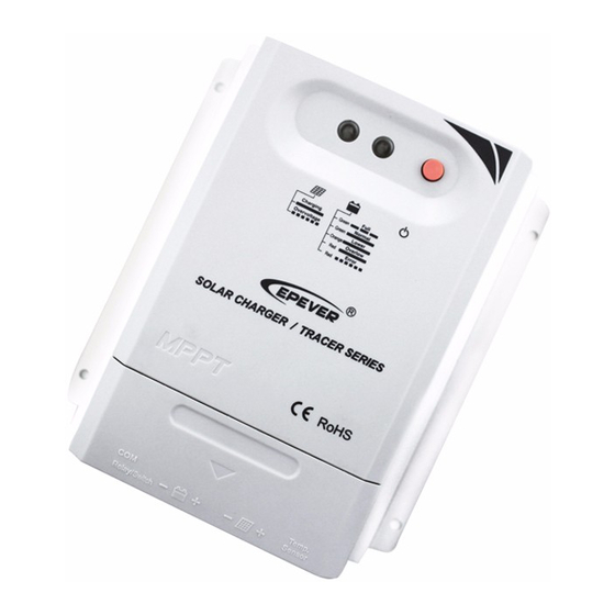
1.2 Characteristics ① ② ③ ⑨ ⑧ ⑦ ⑤ ④ ⑥ Figure 1-1 Tracer-CN Series Characteristics Item Name Item Name ① ⑥ Charge LED Indicator Battery Terminals ⑦ ② Battery LED Indicator Remote Button Port ⑧ ③ Dry Contact Switch Button Dry Contact Port ①... -
Page 6: Optional Accessories
1.3 Optional Accessories 1) Remote Temperature Sensor (Model:RTS300R47K3.81A) Acquisition of battery temperature for undertaking temperature compensation of control parameters, the standard length of the cable is 3m (length can be customized). The RTS300R47K3.81A connects to the port (④) on the controller. NOTE: Unplug the RTS, the temperature of battery will be set to a fixed value 25º... - Page 7 &V the greater the discrepancy between I &I . The greater the discrepancy Bat, between array and battery,the bigger reduction of the conversion efficiency of the system, thus the controller‟s conversion efficiency is particularly important in the PV system. Figure 1-2 is the maximum power point curve, the shaded area is charging range of traditional solar charge controller (PWM Charging Mode), it can obviously diagnose that the MPPT mode can improve the usage of the solar energy resource.
-
Page 8: Battery Charging Stage
If the program works improperly after appearing Multi-MPP, the system will not work on the real max power point, which may waste most solar energy resources and seriously affect the normal operation of the system. The typical MPPT algorithm, designed by our company, can track the real MPP quickly and accurately, improve the utilization rate of the array and avoid the waste of resources. - Page 9 gas precipitation or overheating of battery. Boost Charging The Boost stage maintain 2 hours in default, user can adjust the constant time and preset value of boost voltage according to demand. The stage is used to prevent heating and excessive battery gassing. ...
- Page 10 Equalizing charge increases battery voltage, higher than the standard complement voltage, which gasifies the battery electrolyte. The controller will equalize the battery on 28th each month. The constant equalization period is 0~180 minutes. If the equalization isn‟t accomplished in one-time, the equalization recharge time will be accumulated until the set time is finished.
-
Page 11: Installation Instructions
2Installation Instructions 2.1 General Installation Notes Before installation, please read through the entire installation instructions to get familiar with the installation steps. Be very careful when installing the batteries, especially flooded lead-acid battery. Please wear eye protection, and have fresh water available to wash and clean any contact with battery acid. - Page 12 be calculated. The below table is for reference only. Tracer2210CN/EM1; Tracer3210CN/EM1: 36cell 48cell 54cell 60cell System Voc<23V Voc<31V Voc<34V Voc<38V voltage MAX. Best MAX. Best MAX. Best MAX. Best 72cell 96cell System Thin-Film Module Voc<46V Voc<62V voltage Voc>80V MAX. Best MAX.
-
Page 13: Wire Size
table below: Rated Charge Rated Charge Max. PV Array Max. PV open circuit Model Current Power Power voltage 260W/12V 780W/12V Tracer2210CN/EM1 ① 520W/24V 1560W/24V ② 390W/12V 1170W/12V 100V Tracer3210CN/EM1 780W/24V 2340W/24V ①At 25℃ environment temperature ②At minimum operating environment temperature 2.3 Wire Size The wiring and installation methods must conform to all national and local electrical code requirements. -
Page 14: Mounting
2.4Mounting CAUTION: The controller requires at least 150mm of clearance above and below for proper air flow. Ventilation is highly recommended if mounted in an enclosure. WARNING: Risk of explosion! Never install the controller in a sealed enclose with flooded batteries! Do not install in a confined area where battery gas can accumulate. - Page 15 1) Connect components to the charge controller in the sequence as shown above and pay much attention to the “+” and “-”. Please don‟t turn on the fuse during the installation. When disconnecting the system, the order will be reserved. 2) After installation, power the controller and check the battery LED indicator on.
-
Page 16: Operation
3Operation 3.1LED Indictor Instruction LED Indicator Color Indicator Status PV connection normal but low Green On Solid voltage(irradiance) from PV, no charging Green Slowly Flashing In charging No PV voltage(night time) or Green PV connection problem Green On Solid Normal Green Slowly Flashing Full... - Page 17 Example 2: It can control the DC contactor coil through this dry contact so as to achieve the control of the DC device operation. 2) Light ON/OFF 3) Light ON + Timer1 4) Real-time Control Control the dry contact ON/OFF time through setting real-time clock.
-
Page 18: Parameters Setting And Monitoring
3.3Parameters Setting and Monitoring 1) APP Software ① Cables USB to RS-485 converter cable (Model:CC-USB-RS485-150U-3.81). OTG cable (Model: OTG-12CM). ②Setting Way APP software can be downloaded from the website of http://www.epsolarpv.com. Install the downloaded software. Connect the Mobile phone and controller using above cables. 2) PC Solar Station Monitor ①... -
Page 19: Battery Type
3.4Battery Type ①Sealed(Default) ②Gel ③Flooded ④ User(Apply to PC software “Solar Station Monitor”) Battery Voltage Parameters (parameters is in 12V system at 25℃, please use double value in 24V.) Battery charging setting Sealed Flooded User Over Voltage Disconnect 16.0V 16.0V 16.0V 9~17V Voltage... -
Page 20: Protections, Troubleshooting And Maintenance
Protections, Troubleshooting and Maintenance 4.1 Protection PV Over Current The controller will limit charge power in rated charge power. An over-sized PV array will not operate at maximum power point. PV Short Circuit When PV short circuit occurs, the controller will stop charging. Clear it to resume normal operation. -
Page 21: Troubleshooting
4.2 Troubleshooting Faults Possible reasons Troubleshooting Charging LED indicator off during daytime PV array Confirm that PV and battery wire when sunshine disconnection connections are correct and tight falls on PV modules properly 1)Battery voltage 1) Please check the voltage of Wire connection is lower than 9V battery. - Page 22 Check for dirt, nesting insects and corrosion. If so, clear up in time. Check and confirm that lightning arrester is in good condition. Replace a new one in time to avoid damaging of the controller and even other equipments. WARNING:Risk of electric shock! Make sure that all the power is turned off before above operations, and then follow the corresponding inspections and operations.
-
Page 23: Technical Specifications
5 Technical Specifications Electrical Parameters Item Model Tracer2210CN/EM1 Tracer3210CN/EM1 Nominal system voltage 12/24VDC Auto 9V~32V Battery input voltage range Rated charge current Max. PV input power 260W/12V,520W/24V 390W/12V,780W/24V 92V(at 25℃ environment temperature) Max. PV open circuit voltage 100V(at minimum operating environment temperature) (Battery voltage+2V)~72V MPP Voltage range Dry contact control range... -
Page 24: Annex I Conversion Efficiency Curves
Annex I Conversion Efficiency Curves Illumination Intensity: 1000W/m Temp: 25º C Model: Tracer2210CN/EM1 Solar Module MPP Voltage(17V, 30V, 36V) / Nominal System Voltage(12V) Solar Module MPP Voltage(36V, 52V) / Nominal System Voltage(24V) - Page 25 Model: Tracer3210CN/EM1 Solar Module MPP Voltage(17V, 30V, 36V) / Nominal System Voltage(12V) Solar Module MPP Voltage(36V, 52V) / Nominal System Voltage(24V)
-
Page 26: Annex Ii Dimensions
Annex II Dimensions Tracer2210CNDimensions in Millimeters... - Page 27 Tracer3210CN Dimensions in Millimeters Any changes without prior notice! Version number: V1.1...
- Page 28 BEIJING EPSOLAR TECHNOLOGY CO., LTD. Tel: +86-10-82894112 / 82894962 Fax: +86-10-82894882 E-mail:info@epsolarpv.com Website: http://www.epsolarpv.com/ http://www.epever.com/...
Need help?
Do you have a question about the Tracer 2210CN and is the answer not in the manual?
Questions and answers