Table of Contents
Advertisement
Quick Links
Advertisement
Table of Contents

Related Manuals for Epever MP3043-1020P65


Summary of Contents for Epever MP3043-1020P65
- Page 1 Inverter/charger User Manual MP3043-1020P65 MP5043-1020P65...
-
Page 3: Table Of Contents
Contents Important Safety Instructions..............1 Disclaimers....................5 1 General Information.................6 1.1 Overview............................6 1.2 Appearance...........................9 1.3 Naming rules..........................11 1.4 Connection diagram......................... 12 2 Interface....................14 2.1 Indicator............................14 2.2 Button............................15 2.3 Home screen..........................16 2.4 Interface............................17 2.4.1 Real-time data interface....................17 2.4.2 User interface........................ - Page 4 3 Single Installation.................. 45 3.1 Attention............................45 3.2 Wire and breaker size.......................46 3.3 Mounting the inverter/charger....................47 3.4 Wiring the inverter/charger.....................50 3.5 Operate the inverter/charger....................61 4 Parallel Installation................63 4.1 Wire and breaker size for parallel operation..............63 4.2 Precautions for parallel installation..................63 4.3 Parallel operation in single-phase..................
- Page 5 5.2.3 Scenario C: Both PV and Utility are available..............92 5.2.4 Scenario D: The PV is not available, but the Utility is available........ 95 5.3 No battery mode........................97 6 Protections....................98 7 Troubleshooting................... 101 7.1 Battery faults..........................101 7.2 PV faults............................ 103 7.3 Inverter faults...........................105 7.4 Utility faults..........................
-
Page 6: Important Safety Instructions
Important Safety Instructions Please reserve this manual for future review. This manual contains all the safety, installation, and operation instructions for the MP-P65 series solar inverter/charger ("inverter/charger" referred to as this manual). 1. Explanation of symbols To enable users to use the product efficiently and ensure personal and property safety, please read the related words carefully when you encounter the following symbols in the manual. - Page 7 4. Safety cautions before installation When receiving the inverter/charger, please check if there is any damage in transportation. If you find any problem, please contact the transportation company or CAUTION our company in time. When installing or moving the inverter/charger, follow the instructions in the manual.
- Page 8 7. Safety cautions for inverter/charger operation When the inverter/charger works, the shell will generate much heat, and the WARNING temperature is very high. Please do not touch it, and keep it far from the equipment susceptible to high temperature. SURFACE ...
- Page 9 Improper maintenance of the inverter/charger may cause personal injury or equipment damage; It is recommended to wear an antistatic wrist strap or avoid unnecessary contact with the circuit board. The safety mark, warning label, and nameplate on the inverter/charger should be visible, not removed or covered.
-
Page 10: Disclaimers
Disclaimers The warranty does not apply to the following conditions: Damage caused by improper use or inappropriate environment (it is forbidden to install the inverter/charger in the flammable, explosive, dust accumulative, or other severe environments). The actual current/voltage/power exceeds the limit value of the inverter/charger. ... -
Page 11: General Information
1 General Information 1.1 Overview ① MP-P65 series,upgrade hybrid inverter/chargers that support utility charging, oil generator charging solar charging, utility output, inverter output, 120VAC/240VAC split-phase output. This series also support multiple inverters/chargers (up to 6) for extended parallel operation through single-phase or three-phase parallel connection. - Page 12 Support battery mode or non-battery mode. Non-battery mode: simultaneously charging with solar (Main) and Utility (Assist). Advanced SPWM technology and pure sine wave output. PFC technology with high power factor to reduce the grid usage, low harmonic content of AC current. ...
- Page 13 output to Utility bypass output ≤1ms. With battery activation function (PV, Utility can be activated). MP-P65 series, when using the oil engine as AC input, can be compatible with most oil engines on the market. For a long time and do not use the machine and the machine is in standby mode, when the battery voltage is lower than the minimum input voltage range (36VDC), the machine will automatically cut off all power supply system and to ensure the safety of storage battery life.After the Utility or PV connected, inverter/charger will activate the battery again.
-
Page 14: Appearance
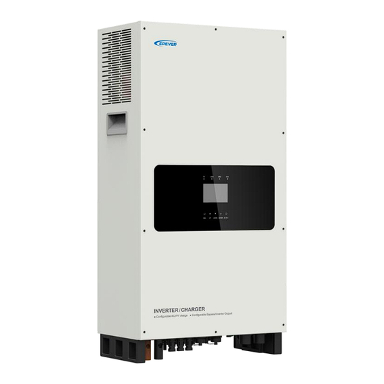
1.2 Appearance... - Page 15 Note: The product appearance and wiring terminals of MP3043-1020P65 and MP5043-1020P65 are the same. The terminals of MP3043-1020P65 are used as an example to be introduced above. ❶ ❽ Instruction Instruction ❷ ❾ LCD (see chapter 2) Temperature sampling port of remote battery ❸...
-
Page 16: Naming Rules
BMS of other manufacturers. The pins of the BMS communication port (USB-A 3.0) as above in (4). currently supported manufacturers corresponding parameters,please refer to the EPEVER’s official website for check or download. CAUTION 1.3 Naming rules... -
Page 17: Connection Diagram
1.4 Connection diagram No battery mode ... - Page 18 Battery mode ...
-
Page 19: Interface
2 Interface Note: The display screen can be viewed clearly when the angle between the end-user's horizontal sight and the display screen is within 90°. If the angle exceeds 90°, the information on the display screen cannot be viewed clearly. 2.1 Indicator Indicator Status... -
Page 20: Button
2.2 Button Button Operation Instruction Exit the current interface Click Switch from the "home screen" to the "Main Table Data Information" screen. Browse interface: Up/Down Click Parameters setting interface: Increase or decrease the parameter value per step size. Parameters setting interface: Increase or decrease the Press and hold (≥3s) parameter value per 10 times the step size. -
Page 21: Home Screen
2.3 Home screen Instruction ❶ Displays the system time, current battery type, and charging state. When the BMS communication is normal, the icon will be shown on the far right, while when it is abnormal, the icon will be shown on the same position. ❷... -
Page 22: Interface
❺ Load icon: indicates that AC output is normal. indicates that there is no AC output. AC output voltage / AC output power Battery status: The battery is discharging. ❻ The battery is being charged. Battery voltage / battery current / lithium battery real-time SOC (displays "--" without lithium battery). -
Page 24: User Interface
2.4.2 User interface After powering on the inverter/charger, the home screen shows up. Click the "ESC" button to enter the "Main Table Data Information" screen. Click the "ENTER" button to enter the next interface, or click the "UP/DOWN" button to browse the current screen display. "User Data Setup"... -
Page 25: Administrator Interface
password. The default parameters and setting range refer to chapter 2.5.1 Parameters list. 2.4.3 Administrator interface After powering on the inverter/charger, the home screen shows up. Press and hold the "ENTER" button to enter the password interface. Input the password correctly to check all parameters or modify them. -
Page 26: Parameters Setting
2.5 Parameters setting 2.5.1 Parameters list Enter the "Set Data Navigation" interface according to chapter 2.4.3 Administrator interface. Then click the "UP/DOWN" button to select navigation 1 to 9 for detail settings. Default parameters and setting ranges are shown in the following table. Note: On the parameter setting interface, click the "UP/DOWN"... - Page 27 (OverFreqDisconnect minus 2.5Hz) and 60.0Hz. User define: 0A to 50.0A, step size: 0.1A 50.0A The current at the battery terminal during Utility charging for MP3043-1020P65. MaxCharge Current (Max. Utility charging current) User define: 0A to 80.0A, step size: 0.1A. 80.0A The current at the battery terminal during Utility charging for MP5043-1020P65.
- Page 28 Parameters Default User define User define: 0A to 18.0A for MP3043-1020P65, step size: 0.1A Note: When the Utility is in charging and bypass 18.0A state, and the actual Utility input current is greater than the set "MaxUtiltyInCurent," the charging current will be decreased until 0A after the Utility input current reaches the set value.
- Page 29 Parameters Default User define User define: (Auxiliary module ON voltage plus 0.2*N) to (Charging limit voltage) (N=Rated battery AuxiliaryOff Volt voltage/12), step size: 1 53.0V (Auxiliary module Off voltage) Note: In PV charging priority mode, stop Utility charging when the battery voltage is greater than this value.
- Page 30 Parameters Default User define Only "ChargeControlMode" is set as the effect of the “SOC." The battery SOC is higher than or equals to the SOC value, and the inverter/charger Full Discnnct Soc will charging automatically. 100% User define: 60% to (Full energy disconnect Soc plus 5%) to 100% or 80% to 100%, step size: 1% Note: Take the maximum value between (Full energy disconnect Soc plus 5%) and 80%.
- Page 31 Parameters Default User define Only "ChargeControlMode" is set as the effect of the “SOC". UtiltyChargeOnSoc (Utility User define: 20% to 50%, or 20% to (Utility charging charging on Soc) off Soc minus 10%), step size: 1% Note: Take the minimum value between 50% and (Utility charging off Soc minus 10%).
- Page 32 Parameters Default User define User define: Rev, NO, HAVE Note: After setting, restart the inverter/charger for BAT Have (Battery have or not) HAVE the setting to take effect. If the Rev is set, the system will be automatically adjusted to the battery mode.
- Page 33 Parameters Default User define User define: DISABLE, ENABLE This parameter is for automatic equalizing charging. Set this value as "ENABLE," the inverter/charger Equalize Enable DISABLE performs the equalize charging automatically. And the default value will be restored to "DISABLE" after inverter/charger restarting.
- Page 34 Parameters Default User define User define: Grid, Generator When the AC input is a generator, this parameter needs to be set to "Generator" to improve the charging capability. AC Input Mode Grid Note: If the AC input mode does not match the AC source of the actual input, the normal operation of the inverter/charger will be affected.
- Page 35 Parameters Default User define User define: 0-254, step size: 1 BMS Protocol Note: Refer to the Lithium battery protocol file. BMS Com Method RS485 Read-only User define: OPEN, CLOSE Led Switch OPEN Turn on/off the PV/LOAD/GRID/RUN indicators. User define: DISABLE, ENABLE Set this value as "ENABLE,"...
- Page 36 Parameters Default User define User define: Default (25 ℃ ), BMS_ET (BMS environment temperature), BMS_C_MaxT (BMS cell maximum temperature), BMS_C_MinT (BMS cell minimum temperature), RS485, DSP The MAP table calculates the charging and discharging current values based temperature and SOC value of the lithium battery. When the lithium battery has BMS function and supports temperature upload, set “MAP TEMP TEMP...
- Page 37 Parameters Default User define 9. Bat Control Data Setup (Set the "BAT Set Mode" as "Expert" first) BAT Set Mode (Battery set Expert Read-only mode) System voltage level Read-only 48V battery type: AGM, GEL, FLD, LFP15S, Battery type LFP16S, LNCM13S, LNCM14S User define: (Charging limit voltage plus 0.1V) to OverVoltDiscnect (Over voltage 64.0V...
-
Page 38: Battery Voltage Control Parameters (Smart)
Parameters Default User define User define: (Discharging limit voltage) to (Low LowVoltDisconect (Low voltage 44.4V voltage reconnect voltage minus 0.1V), step size: disconnect voltage) 0.1V User define: "N*9 ≤ Discharging limit voltage < Under voltage warning voltage" and "Discharging DischrgeLimitVolt (Discharging 42.4V limit voltage <... - Page 39 B. Over Voltage Disconnect Voltage > Over Voltage Reconnect Voltage C. Low Voltage Reconnect Voltage > Low Voltage Disconnect Voltage ≥ Discharging Limit Voltage D. Under Voltage Warning Recover Voltage > Under Voltage Warning Voltage ≥ Discharging Limit Voltage E. Boost Voltage Reconnect Voltage > Low Voltage Reconnect Voltage 2) Lithium battery voltage control parameters Battery Type LFP15S...
-
Page 40: Battery Work Modes
When setting the Lithium battery voltage control parameters, the following rules must be obeyed. Over Voltage Disconnect Voltage < Over Charging Protection Voltage (BMS Circuit Protection Modules) minus 0.2V Over Voltage Disconnect Voltage > Charging Limit Voltage ≥ Equalize Charging Voltage ≥ Boost Charging Voltage ≥... - Page 41 2. Normal communication 1. Lithium battery pack with protective board only (no The inverter/charger controls See Figure 4 “Setting BMS) charging and discharging process for lithium battery 2. No communication based on the pre-set MAP pack with protective board (A smart remote temperature table.
- Page 42 Figure 2 “Setting process for lithium battery pack with BMS and current control function” When the system adopts a lithium battery pack with BMS and current control function at the end of charge and discharge, and the lithium battery pack can communicate with the inverter/charger normally, follow the flowchart below to set parameters correctly.
- Page 43 The inverter/charger controls charging and discharging based on the read BMS values. Please go to EPEVER official website to download the currently supported BMS manufacturers and the BMS parameters. The inverter/charger will control charging and discharging based on the LCD settings after setting the “BMSCurent Select”...
- Page 44 Due to the different charging and discharging characteristics and voltage consistency of lithium batteries from different manufacturers, it is necessary for professionals to guide the use of VIRTUAL_BMS for charging and discharging. Figure 3 “Setting process for lithium battery pack with BMS, without current control ...
- Page 46 The inverter/charger will control charging and discharging based on the LCD settings after setting the “BMS Current Select” as “INVALID.” Due to the different charging and discharging characteristics and voltage consistency of lithium batteries from different manufacturers, it is necessary for professionals to guide the use of VIRTUAL_BMS for charging and discharging.
- Page 47 The inverter/charger will control charging and discharging based on the LCD settings after setting the “BMSCurent Select” as “INVALID.” Due to the different charging and discharging characteristics and voltage consistency of lithium batteries from different manufacturers, it is necessary for professionals to guide the use of VIRTUAL_BMS for charging and discharging.
-
Page 48: Gird Feed Function
2.5.5 Gird feed function Connect the inverter/charger to the Utility and PV, the gird feed function will be enabled (as shown in table 1) after the battery voltage reaches the target voltage and there still exist excess PV energy. The inverter/charger will feed the excess PV energy to the grid as per the “Gird feed current,” which will maximize the PV energy utilization. -
Page 49: Password Modifying
2.5.7 Password modifying Enter the "Set Data Navigation" interface according to chapter 2.4.3 Administrator interface. Then click the "UP/DOWN" button to select "8 PassWord Setup", and click the "ENTER" button to enter the password modifying interface. Click the "ENTER" button to move right, click the "AC OUT"... -
Page 50: Single Installation
3 Single Installation 3.1 Attention Please read the manual carefully to familiarize yourself with the installation steps. Be very careful when installing the batteries, especially flooded lead-acid batteries. Please wear eye protection, and have fresh water available to rinse if contact with battery acid. ... -
Page 51: Wire And Breaker Size
PV module's Isc. The PV array's Isc must not exceed the maximum PV input current. When three PV arrays are connected independently, the wire and circuit breaker size of each PV array are as follows: Model PV wire size Breaker size MP3043-1020P65 10mm /7AWG 2P—50A/250VDC MP5043-1020P65... -
Page 52: Mounting The Inverter/Charger
Recommended AC output wire size Breaker size Model Load wire size MP3043-1020P65 /11AWG 2P-25A/250VAC MP5043-1020P65 /9AWG 2P-40A/250VAC If the distance between the inverter/charger and the PV array, and distance between the inverter/charger and the battery is long, larger wires shall be used to reduce the voltage drop and improve the system's performance. - Page 53 Step 2: Fix the mounting plate (included accessory) to the inverter/charger. Mounting plate size (mm)
- Page 54 Step 3: Fix the wall hanger (included accessory) to the wall, and put the inverter/charger on it. Wall hanger...
-
Page 55: Wiring The Inverter/Charger
> ❹PV ❺Utility or Generator > ❻Optional accessories”, and disconnect the inverter/charger in the reverse > order. The following wiring sequence is illustrated in the appearance of "MP3043-1020P65." For wiring positions of other models, please refer to the actual product appearance. - Page 56 No battery mode in regions with single-phase power grid ...
- Page 57 No battery mode in regions with split-phase power grid ...
- Page 58 Battery mode in regions with single-phase power grid ...
- Page 59 Battery mode in regions with split-phase power grid Grounding The inverter/charger has a dedicated grounding terminal, which must be grounded reliably. The grounding wire size must be consistent with the recommended load wire size. The grounding connection point shall be as close as possible to the inverter/charger, and the total grounding wire shall be as short as possible.
- Page 60 Do not ground the AC input L or N terminals between the inverter/charger and the household power distribution cabinet. Do not ground the AC output L or N terminals. The cabinet of the inverter/charger is connected to earth through the ...
- Page 61 Connect the AC load Risk of electric shock! When wiring the AC load, please disconnect the circuit breaker and ensure that the poles' leads are connected correctly. The AC loads shall be determined by the continuous output power of the WARNING inverter/charger.
- Page 62 Load connection diagram in regions with split-phase power grid In regions with split-phase power grid (such as North America and Japan), as well as in regions with single-phase power grid, the load connection terminals are respectively shown in the above diagram. In regions with split-phase power grid, connect different pins of the load connection terminal to obtain different AC power.
- Page 63 Connect the Utility or generator Risk of electric shock! The Utility input can generate dangerous high-voltage! Disconnect the circuit breaker or fast-acting fuse before wiring, and ensure that the poles' leads are connected correctly. After the Utility is connected, the PV and battery cannot be grounded, and the WARNING inverter/charger cover must be grounded reliably to shield the outside electromagnetic interference effectively and prevent the cover from causing...
- Page 64 Utility or generator connection diagram in regions with single-phase power grid Utility or generator connection diagram in regions with split-phase power grid ...
- Page 65 Connect optional accessories Connect the remote battery temperature sensor cable Connect one end of the remote battery temperature sensor cable to the REMOTE T interface port and place the other end close to the battery. Under the non-lithium battery system or lithium batteries that do not have temperature sampling,the charging or discharge will be compensated according to the temperature after connecting an external temperature sensor.
-
Page 66: Operate The Inverter/Charger
3.5 Operate the inverter/charger Step 1: Double-check whether the wire connection is correct. Step 2: Connect the battery circuit breaker and turn on the power switch (keep flicks). The LCD will be lit, which means the system running is normal. First to turn off the circuit breaker of the battery. - Page 67 Step 3: Set parameters by the buttons. For detailed parameters setting, refer to chapter 3.4 Parameters setting. CAUTION Step 4:Use the inverter/charger. Connect the load circuit breaker, the PV array circuit breaker, and the utility circuit breaker in sequence and plug the utility’s socket. After the AC output is normal, turn on the AC loads one by one. Do not turn on all the loads simultaneously to avoid protection action due to a large transient impulse from the current.
-
Page 68: Parallel Installation
120VAC or 220VAC to 240VAC, and three-phase output voltage is 380VAC to 415VAC. 4.1 Wire and breaker size for parallel operation Recommended battery wire and breaker size when connecting a single inverter/charger. Model Battery wire size Breaker size MP3043-1020P65 20mm /4AWG 2P—150A/125VDC MP5043-1020P65 35mm /2AWG 2P—250A/125VDC... - Page 69 Please disconnect the circuit breaker before wiring and ensure that the leads of the "+" and "-" poles are polarity correctly. Each inverter/chargers must be connected to one battery pack, with the length of WARNING the connecting wire from each inverter/charger to the battery pack being the different.
-
Page 70: Parallel Operation In Single-Phase
4.3 Parallel operation in single-phase 4.3.1 Single-phase parallel wiring diagram Two inverter/chargers in single-phase parallel Connect the battery, utility and load in regions with single-phase power grid ... - Page 71 Connect the battery, utility and load in regions with split-phase power grid Connect the parallel communication cables Connect the parallel communication ports ( USB-A 3.0 ports ) on the side of each inverter/charger by the parallel communication cables. Connect the CAN bus terminal resistor ( USB-A 3.0 connector ) ,included accessory, to the parallel communication ports ( USB-A 3.0 ports ) of the first and last inverter/charger.
- Page 72 Three or more inverter/chargers in single-phase parallel Connect the battery, utility and load in regions with single-phase power grid ...
-
Page 73: Debug For Single-Phase Parallel
Connect the battery, utility and load in regions with split-phase power grid Connect the parallel communication cables Connect PV PV connection refers to chapter “3 Installation>3.4Wiring the inverter/charger>Connect the PV modules”. Each inverter/charger should be connected to PV modules separately, and it is prohibited to connect the same PV modules to two or more inverter/chargers. - Page 74 connected to the combiner box or busbar. Otherwise, uneven loading of each inverter/charger in the bypass mode will occur. Ensure that all circuit breakers for the battery, utility input, load side and PV are disconnected. Step 2: Connect the circuit breakers on the battery side in sequence to turn on each inverter/charger, set the phase of each inverter/charger to “Single”...
- Page 75 Parallel in single-phase, Master unit: S (M)-6 S Parallel in single-phase, Slave unit: S (S)-6 S If the parallel status icon displayed on the LCD is consistent with the actual phase and startup quantity of the inverter/chargers, it indicates that the phase setting and parallel communication have been successful.
-
Page 76: Parallel Operation In Three-Phase
inverter/charger. After the inverter/charger is powered on, the AC output is turned on by default. Before turning on the power switch of the inverter/charger, please confirm that the AC output is correctly connected to the load and there is no safety hazards present. 4.4 Parallel operation in three-phase 4.4.1 Three-phase parallel wiring diagram When paralleling in three-phase(Phase A, Phase B and Phase C), the number of parallel units in each... - Page 77 Two for Phase A, two for Phase B, and two for Phase C Connect the battery, utility and load Connect the parallel communication cables Connect the parallel communication port (USB-A 3.0) on the side of each inverter/charger by the ...
- Page 78 One for Phase A, one for Phase B, and one for Phase C Connect the battery, utility and load Connect the parallel communication cables ...
- Page 79 Two for Phase A, one for Phase B, and one for Phase C Connect the battery, utility and load Connect the parallel communication cables Two for Phase A, two for Phase B, and one for Phase C Connect the battery, utility and load ...
- Page 80 Connect the parallel communication cables Three for Phase A, one for Phase B, and one for Phase C Connect the battery, utility and load ...
- Page 81 Connect the parallel communication cables Three for Phase A, two for Phase B, and one for Phase C Connect the battery, utility and load Connect the parallel communication cables ...
-
Page 82: Debug For Three-Phase Parallel
Four for Phase A, one for Phase B, and one for Phase C Connect the battery, utility and load Connect the parallel communication cables Connect PV PV connection refers to chapter “3. Single Installation > Wiring the inverter/charger > Connect the PV modules”. - Page 83 Ensure that the wiring of AC input and AC output are connected separately and uniformly connected to the combiner box or busbar. Otherwise, it will cause uneven loading of each inverter/charger in the bypass mode. Ensure that all breakers for the battery side, utility input side, load side and PV side are open. ...
- Page 84 Parallel parameters setting for Phase C After three-phase wiring is completed, the “Phase Set” of each inverter/charger in Phase C needs to be changed to “Phase C.”See the example of screen display on the slave unit for two inverter/chargers in Phase C below.
- Page 85 Step 3: Turn on each inverter/charger, the parallel status icon will display. See the example of three-phase parallel operation of 6 units as below (2 units each in Phase A, B and C). For other numbers of units in three-phase parallel operation, only the “number of parallel” displays differently.
- Page 86 WARNING to Phase A, B and C, make sure the phase connection is the same as the setting in “Phase Set”. Or when “Phase Set” of the inverter/charger is set as “Phase A/B/C”, the utility input can be connected according to the line sequence of A/B/C, B/C/A and C/A/B.
-
Page 87: Bms Connection For Parallel Equipment
4.4.3 BMS connection for parallel equipment 4.4.4 BMS wiring diagram for parallel In either single-phase application or three-phase application, lithium batteries can be connected to the BMS communication port of any inverter/charger through the BMS communication cable. All parallel equipment must be connected to the same lithium battery bank. Wiring diagram is as below: 4.4.5 BMS parameter setting for parallel Select battery type ... - Page 88 To setting the “Charging and discharging,” BMS Valid/Invalid, BMS voltage control enable, BMS current control choose.” After BMS connection is completed, related BMS parameters need to be set on the LCD of the connected inverter/charger, to set “BMS Valid/Invalid” as “VALID,” set “BMSVltCntrlEnable” as “ENABLE,”...
- Page 89 Step 1: Based on the manufacturer information of the lithium battery connected to the inverter/charger, determine the lithium battery conversion communication protocol number PRO (Go to EPEVER website and download the “BMS Communication Protocols & Fixed ID” file to obtain the corresponding PRO numbers for different lithium battery manufacturers).
-
Page 90: Bms Control Logic For Charging And Discharging
number. Step 3: After setting the BMS parameters, return to the home screen, where the word “BMS” is displayed in the upper right corner, indicating the BMS connection is successful. 4.4.6 BMS control logic for charging and discharging In either single-phase application or three-phase application, after the BMS is correctly connected and BMS parameters are set correctly, the system will follow the following logic to control the charging and discharging of lithium battery. - Page 91 Enter the “BMS DATA” screen, click the "UP/DOWN" button to view the parameter. No matter a single battery pack is used or multiple battery packs in parallel are used, ① ChgCurntLimit the “Charge current Limit” of each parallel ① DischagCurntLimit unit= “BMSCharginCurrent”...
-
Page 92: Parameters Sync Update Item
If the parameters read from the BMS include the BMSCharginCurrent and BMSDisChageCurrt (viewed through the "BMS DATA" screen), set related CAUTION parameters according to the “2.5.4 Battery work modes” in the user manual. 4.5 Parameters sync update item Power on the inverter/charger, after the communication is normal, part of the parameters of the slave device will automatically synchronize with that of the host device. - Page 93 When the following parameters are set on any inverter/charger, will automatically interface synchronized to all the other inverter/chargers. *OutputVoltLevel *OutputFrequency UnbalanceSet *Phase Set Load Data UnbalanceValue (Note: After setting these Setup PAR ChageCurent parameters, it will only take PARDisChageCurent effect after restarting all the inverter/chargers.) *OverVoltDisconnect *OverVoltReconnect...
- Page 94 Load Open/Close Invert Open/Close PV Charge Open/Close AC Charge Open/Close Charge Enable Discharge Enable Battery Type BoostRecnectVolt OverVoltDiscnect LowVoltReconect ChargingLimitVolt UndrVltWarnRecvr Bat Control OverVoltReconect UnderVolt Warn Data Setup EqualizeChagVolt LowVoltDisconect BoostCharginVolt DischrgeLimitVolt FloatChagingVolt Note: When the slave devices are powered on, parameters marked with will not automatically synchronize the parameter values of the host device , and they need to be set manually.
-
Page 95: Working Modes
5 Working Modes 5.1 Abbreviation Abbreviation Instruction PV power Load power LOAD Battery voltage Low Voltage Disconnect Voltage Low Voltage Reconnect Voltage Low Energy Disconnect SOC Low Energy Disconnect Recover SOC Auxiliary module OFF voltage (namely, Utility charging OFF voltage) Auxiliary module ON voltage (namely, Utility charging ON voltage) Utility Charging OFF SOC Utility Charging ON SOC... -
Page 96: Scenario B: Pv Is Available, But The Utility Is Not Available
Set the "Charge Control Mode" as "VOLT"; the working mode is determined by the battery voltage value. Set the "Charge Control Mode" as "SOC," the working mode is determined by the battery SOC. The battery SOC value will be more accurate after a full CAUTION charge-discharge cycle when the "Charge Control Mode"... -
Page 97: Scenario C: Both Pv And Utility Are Available
5.2.3 Scenario C: Both PV and Utility are available. Discharging Mode: "PV>BP>BT" Charging Mode: "Solar" ❶ When the PV power is greater than load "PV>BT>BP" power, the PV charges the battery and supplies extra power to the load. > P ≤... - Page 98 ❷ When the battery voltage reaches to the Boost charging voltage or Equalize charging voltage, and the PV input power is greater than the battery charging power, the Utility and PV supply power to the load, and the PV charges the battery simultaneously.
- Page 99 (C-4) Charging Mode: "Solar prior" Discharging Mode: "BP>PV>BT" ❶ When the battery voltage reaches to the Boost charging voltage or Equalize charging Utility voltage, and the PV input power is greater than the battery charging power, the Utility and PV supply power to the load, and the PV charges the battery at the same time.
-
Page 100: Scenario D: The Pv Is Not Available, But The Utility Is Available
❷ When the PV power is lower than or equal to the (MCC* V ), the Utility and PV charge the battery, and the Utility supplies power to the load. Charging Mode: "Utltyprior" Discharging Mode: Un-programmable (C-6) The Utility supplies power to the load and charges the battery simultaneously. - Page 101 ❶Any of the following is satisfied, the battery Charging Mode: "Solar prior" Discharging Mode: "PV>BT>BP" supplies the load. The battery voltage is higher than or equal to the AOF value. The battery SOC is greater than or equal to (D-3)...
-
Page 102: No Battery Mode
Charging Mode: "Utly & solr" Discharging Mode: Un-programmable or "Utltyprior" (D-5) The Utility supplies power to the load and Utility charges the battery simultaneously. 5.3 No battery mode Note: Under the no battery mode, the "Charging Mode" and "Discharging Mode" settings will not take effect.In no battery mode, the maximum load power is about 80% of the PV power when the PV is loaded. -
Page 103: Protections
6 Protections Protections Instruction When the PV array's actual charging current/power exceeds its PV limit Current/ rated current/power, it will charge the battery as per the rated Power current/power. When the PV is not charging and short circuit, the inverter/charger is PV short circuit not damaged. - Page 104 Protections Instruction When the battery voltage goes higher than the [Over Voltage Battery overvoltage Disconnect Voltage], the inverter/charger will stop charging the battery to protect the battery from being over-charged. When the battery voltage goes lower than the [Low Voltage Battery Disconnect Voltage], the inverter/charger will stop discharging the over-discharge...
- Page 105 Protections Instruction When the internal temperature overheats, the inverter/charger will stop charging/discharging. Device overheating The inverter/charger will resume charging/discharging when the internal temperature is normal and the protection time lasts more than 20 minutes.
-
Page 106: Troubleshooting
7 Troubleshooting After the inverter/charger is powered on, the meter displays the boot screen all the time (unable to enter the home screen) and the red "RUN" indicator flashes. It means the communication with the inverter/charger is error. When the above fault occurs, check CAUTION whether the communication cable is disconnected. - Page 107 ② Error ① Fault/Status Indicator Buzzer Solution code Disconnect the PV and Utility, and test if the voltage at the additional BatOV (Battery Err55 battery port is too high, or test if the setting value of the battery's "over over-voltage) voltage disconnect voltage"...
-
Page 108: Pv Faults
7.2 PV faults Error ① ② Fault/Status Indicator Buzzer Solution code PV Error 1 Err00 This fault will occur simultaneously with one or more other items of PV Error 2 Err01 the "PV faults." Please refer to the solutions for other items. PV Error 3 Err02 PV1 OC (PV1 over... - Page 109 Error ① ② Fault/Status Indicator Buzzer Solution code PV1OCS (PV1 soft over current) Err66 PV2OCS (PV2 soft over Check if the PV input power exceeds the maximum PV input power Err70 current) allowed by the inverter/charger. Err74 PV3OCS (PV3 soft over current) indicator Intermittent...
-
Page 110: Inverter Faults
7.3 Inverter faults Error ① ② Fault/Status Indicator Buzzer Solution code This fault will occur simultaneously with one or more other items of Inv Error (Inverter error) Err04 the "Inverter faults". Please refer to the solutions for other items. InvLVSft_OC (Inverter low Err33 voltage soft over current) Check if the load actual power exceeds the “Continuous output... -
Page 111: Utility Faults
only displays the fault code with the smallest value. ②Set the "BuzzerAlert" as "ON," the buzzer will sound when a fault occurs. After the fault is eliminated, the buzzer will automatically mute. If the "BuzzerAlert" is set as "OFF," even if a fault occurs, the buzzer will not sound. Note: the "BuzzerAlert"... -
Page 112: Load Faults
①The fault/status code is displayed in the "Status" column at the bottom right corner of the LCD. When multiple faults occur simultaneously, the LCD only displays the fault code with the smallest value. ②Set the "BuzzerAlert" as "ON," the buzzer will sound when a fault occurs. After the fault is eliminated, the buzzer will automatically mute. If the "BuzzerAlert"... -
Page 113: Other Faults For Single Inverter/Charger
"BuzzerAlert" is set as "OFF," even if a fault occurs, the buzzer will not sound. Note: the "BuzzerAlert" defaults to "ON". 7.6 Other faults for single inverter/charger ② Error ① Fault/Status Indicator Buzzer Solution code Check if the load is short circuited or if the power exceeds the allowable TZError Err25 output power of the inverter/charger, or if the input voltage of the battery... - Page 114 ② Error ① Fault/Status Indicator Buzzer Solution code Transformer OT LOAD Ensure the inverter/charger is installed in a cool and well-ventilated (Transformer over Err60 indicator place. temperature) red ON When the bus voltage fluctuates above the under-voltage point by more VBUSOSC (Voltage bus Err79 than 4.5V three times, it is determined as VBUSOSC (Voltage bus...
-
Page 115: Parallel Faults
7.7 Parallel faults Error ② Fault/Status Indicator Buzzer Solution ① code CAN communication Check if the parallel connection cable and the CAN communication (USB-A 3.0 Err80 failure port) are securely connected. PhaseLoss Error Err81 (Phase loss error) Check if the phase setting of the inverter/charger is correct. If not, correct it and UnSet Phase (Unset restart the inverter/charger. - Page 116 Error ② Fault/Status Indicator Buzzer Solution ① code PhaseCAP Error (Utility phase Err88 capture error) Check if the frequency and voltage of the Utility fluctuate excessively. VoltTrace Error (Utility voltage Err89 tracing error) BatInconsistent Check the battery status and settings of the host and slave inverter/chargers, (Battery mode Err90 and then restart the slave devices.
- Page 117 Error ② Fault/Status Indicator Buzzer Solution ① code BatInconsistent Check the battery status and settings of the host and slave (Battery mode Err98 LOAD Intermittent inverter/chargers, and then restart the slave devices. inconsistent) indicator beeps for red ON Check if the parallel connection cable and the CAN communication (USB-A LocalPhaseCAPErr Err99 3.0 port) are securely connected.
-
Page 118: Bms Faults
7.8 BMS faults Error ① Fault/Status Indicator Buzzer Solution code BMS OVP (BMS over voltage protect) Err114 BMS Chage TEMP ERR (BMS charge Err116 temperature error) Check the BMS communication status or BMS setting BMS UVP (BMS under voltage protect) Err117 parameters. -
Page 119: Maintenance
8 Maintenance The following inspections and maintenance tasks are recommended at least twice yearly for best performance. Make sure no block on airflow around the inverter/charger. Clear up dirt and fragments on the radiator. Check all the wired cables to ensure insulation is not damaged for serious solarization, frictional ... -
Page 120: Specifications
9 Specifications Model MP3043-1020P65 MP5043-1020P65 Rated battery voltage 48VDC Battery work voltage range 42.4VDC to 64.0VDC Battery type Lithium battery/lead-acid battery Inverter output Continuous output power(@25℃/4H) 3000W 5000W 5S Continuous output power (@25℃) 6000W 10000W Rated output voltage 220VAC/230VAC/240VAC±5%; 110VAC/115VAC/120VAC±5% Rated output frequency 50Hz/60Hz±0.5Hz... - Page 121 Model MP3043-1020P65 MP5043-1020P65 Static consumption ≤ 48V/ 0.15A Enclosure IP65 Relative humidity < 95% (N.C.) 4000m (If the altitude exceeds 2000 meters, the actual output Altitude power is reduced appropriately)★ -20℃ to 55℃ (When the environment temperature exceeds Work temperature 25℃, the actual output power is reduced appropriately)★...
-
Page 122: Dimensions
10 Dimensions Model: MP3043-1020P65 (Unit: mm) - Page 123 Model: MP5043-1020P65 (Unit: mm) Any changes without prior notice! Version number: V2.0...
- Page 124 HUIZHOU EPEVER TECHNOLOGY CO., LTD. Tel: +86-752-3889706 E-mail: info@epever.com Website: www.epever.com...
Need help?
Do you have a question about the MP3043-1020P65 and is the answer not in the manual?
Questions and answers