Table of Contents
Advertisement
Advertisement
Table of Contents

Subscribe to Our Youtube Channel
Related Manuals for Epever UP1000


Summary of Contents for Epever UP1000
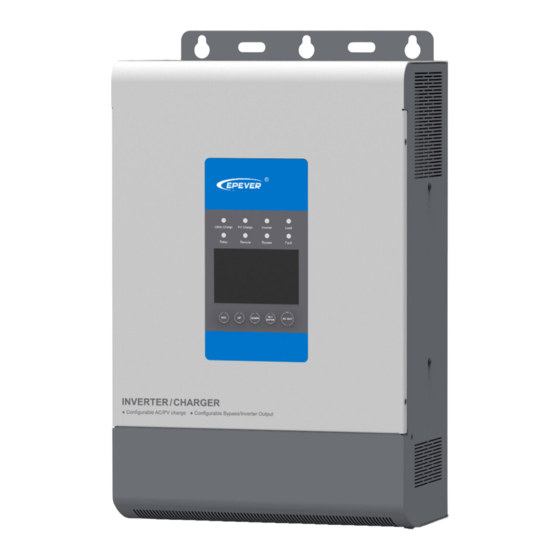
- Page 1 Inverter/charger User Manual Models: UP1000/UP1500 UP2000/UP3000 UP5000...
- Page 3 Important Safety Instructions Please reserve this manual for future review. Please reserve this manual for future review. This manual contains all instructions about safety, installation, and operation for the inverter/charger. Read all the instructions and warnings carefully in the manual before installation. ...
-
Page 5: Table Of Contents
CONTENTS 1. General Information ................ 1 1.1 Overview ..................1 1.2 Characteristics ................2 1.3 Designations of models ..............3 1.4 Schematic Diagram for Connections ........... 4 2. Installation Instructions ..............5 2.1 General Installation Notes ............. 5 2.2 Wire Size& breaker ................ 5 2.3 Mounting .................. -
Page 6: General Information
1. General Information 1.1 Overview UPower is a new energy storage inverter/charger that integrates utility charging, solar charging, and AC output. The high-performance multi-core chip in the product with the advanced control algorithm brings intelligent management of the system. As a reliable industrial standard equipment, UPower has quick response speed and excellent high transfer efficiency. -
Page 7: Characteristics
Four charging modes: Utility priority, Solar priority, Utility & Solar and Solar only Two output modes: Battery and Utility Utility charging and inverter output can work at the same time, which avoids the impact of the unstable Utility voltage on the load ... -
Page 8: Designations Of Models
❶ ❼ Ventilation Dry contact interface ❽ ❷ M4 Screw (2 pcs) Remote interface ❸ ❾ AC output terminals RS485 interface(5VDC/200mA) ❹ ❿ Utility input terminals Inverter/charger switch ❺ ⓫ Battery input terminals PV input terminals ★ ❻ ⓬ interface Terminals cover Temperature Sensor (Model:RT-MF58R47K3.81A)... -
Page 9: Schematic Diagram For Connections
1.4 Schematic Diagram for Connections ❶Utility power supply and ❷Battery power supply can not be carried out simultaneously. Confirm the AC load power compatible with the power of the inverter/charger. AC load selected exceeding the maximum output power of the inverter/charger is prohibited. -
Page 10: Installation Instructions
The utility input and AC output are of high voltage, do not touch the wire connection. 2.2 Wire Size& breaker The wiring and installation methods must follow all national and local electrical code requirements. Recommended wire and circuit breaker of PV Model PV wire size Breaker UP1000-M3212 10mm /8AWG 2P—63A UP1000-M3222 10mm /8AWG 2P—63A... - Page 11 NOTE: When the PV modules are connected in series, the PV array's open-circuit voltage must not exceed the max. PV input voltage at 25℃ environment temperature. Recommended wire of Utility Model Utility wire size UP1000-M3212 2.5mm /14AWG UP1000-M3222 2.5mm /14AWG UP1500-M3222 2.5mm...
-
Page 12: Mounting
Recommended wire and circuit breaker for AC output Model AC wire size Breaker UP1000-M3212 2.5mm /14AWG 2P—10A UP1000-M3222 2.5mm /14AWG 2P—10A 2.5mm /14AWG UP1500-M3222 2P—10A UP2000-M3322 2.5mm /14AWG 2P—16A UP3000-M3322 /12AWG 2P—25A UP3000-M6322 /12AWG 2P—25A UP3000-M2142 /12AWG 2P—25A UP3000-M6142 /12AWG 2P—25A... - Page 13 Installation steps: Step1:Determination of Installation Location and heat-dissipation Space When installing the inverter/charger, ensure enough air flowing through the heat sink. Please leave at least 150mm clearance away from the upper and lower edges. Please see Figure 2-1: Mounting. WARNING: Risk of explosion! Never install the inverter/charger with flooded batteries in a sealed enclosure! Do not install the device in a confined area where battery gas can accumulate.
- Page 14 Connect the remote temperature sensor cable (model: RTS300R47K3.81A) Connect the accessories, monitor the system status, and set the parameters via PC software or APP software. (1)PC software www.epever.com——Inverter Monitor(UP) (2)Mobile APP software (Android) www.epever.com——UPower Step 6:Recheck if the wire connection is correct...
- Page 15 ①Connect the circuit breaker at the battery end. ②Turn on the switch, then the inverter indicator is on. ③Turn on the breaker of PV array and Utility. ④Turn on the AC load when the AC output is normal. When supplying power for different AC loads, it is recommended to turn on the load with a large impulse current.
-
Page 16: Interface Instruction
3. Interface Instruction 3.1 Indicator Indicator Color Status Instruction No utility input Utility connection normal but no On Solid charging Green Slowly Flashing(0.5Hz) Utility charging Fast Flashing(2.5Hz) Utility charge module fault No PV input connection normal On Solid charging Green Slowly Flashing(0.5Hz) PV charging Fast Flashing(2.5Hz) -
Page 17: Buttons
3.2 Buttons Operation Instruction Exit the current interface Press the button Clear the faults Press the button and hold on 2s Browse interface:Up/Down Press the button Setting interface:Up/Down Switch to "Browse Parameter Column" Confirm the setting parameters Press the button Switch the"... - Page 18 Load power 8~25% Load power 25~50% Load power 50~75% Load power 75~100% Item Setting Content Solar priority Utility priority ① INPUT Utility & solar Solar Battery ② OUTPUT Utility AC output voltage AC output current ③ Load AC output power AC output frequency Battery voltage Max.
- Page 19 Float ⑦ Battery charging stage Boost Equalize(28 each month) ① INPUT ★Solar priority(Default) The battery is charged in solar priority mode. When the battery voltage is lower than "Auxiliary Module ON Voltage(V )," the utility starts charging. When the battery voltage reaches "Auxiliary Module OFF Voltage(V ),"...
-
Page 20: Setting Interface
★Utility(Default) 3.4 Setting interface Common interface for common user Operation: Step1: Press the button and hold on 2s at the real-time interface to go to the common interface. Step2: Press the button and hold on 2s at the setting parameter interface and choose the parameters. - Page 21 ℃ ℃/℉ Temperature unit 30S/60S/100S(Always- Backlight time Buzzer alarm switch ON/ OFF ★ User 10.5~11.3V ★ 10.8V Low voltage disconnect voltage ★ step size 0.1V ★ User 12.0~13.0V ★ Low voltage reconnect voltage 12.5V ★ step size 0.1V ★The voltage parameter is at 25℃, 12V system, and twice in 24V system, quadruple in 48V system.
-
Page 22: Other Function
Clear fault ON/OFF Clear the accumulated energy ON/OFF 100~4000AH Total battery capacity 600AH Step size 100AH — Software version U-1.0 ★The voltage parameter is at 25℃, 12V system, and twice in 24V system, quadruple in 48V system. The following rules must be observed when modifying the parameter values in User for lead-acid battery. - Page 23 When Switch 1 is in "ON," the output voltage is selected as 230VAC, and on the contrary as 220VAC; When Switch 2 is in "ON," the output frequency is selected as 60Hz, and on the contrary, like 50Hz. If the output frequency or voltage of the inverter/charger is to be reset;...
-
Page 24: Protection
4. Protection Protection Instruction When the charging current of the PV array exceeds its rated current, it will be charged at the rated current. PV limit Current NOTE: When the PV modules are in series, ensure that the PV array's open-circuit voltage does not exceed the "maximum PV open-circuit voltage."... -
Page 25: Troubleshooting
5. Troubleshooting 5.1 Fault battery Fault Module Code Fault frame indicator Buzzer indicator blink — — Battery low voltage Battery over voltage — Battery over-discharge Battery Flashing Nominal voltage error Low temperature Over-temperature PV charge (PV charge module) charging Fast Communication Fault module Flashing... -
Page 26: Maintenance
6. Maintenance 1)The following inspections and maintenance tasks are recommended at least two times per year for best performance. Make sure the inverter/charger is firmly installed in a clean and dry ambient. Make sure no block on airflow around the inverter/charger. Clear up any dirt and fragments on the radiator. -
Page 27: Technical Specifications
7. Technical Specifications Item UP1000-M3212 UP1000-M3222 UP1500-M3222 UP2000-M3322 UP3000-M3322 UP3000-M6322 Nominal battery voltage 12VDC 24VDC Battery input voltage range 10.8~16VDC 21.6~32VDC Inverter output Continuous output power 800W 800W 1200W 1600W 2400W 2400W Output power (15min.) 1000W 1000W 1500W 2000W 3000W... - Page 28 Charging conversion ≤98% efficiency Temperature -3mV/℃/2V (Default) compensate coefficient Others ≤1.2A ≤0.6A ≤0.6A ≤0.8A ≤0.8A ≤0.8A No load consumption Enclosure IP30 Relative humidity < 95% (N.C.) Environment temperature -20℃~50℃(100% input and output with no derating) <5000m(Derating to operate according to IEC62040 at a height exceeding 1000m) Altitude Mechanical Parameters Dimension(H x W x L)
- Page 29 160VAC~280VAC(Working voltage range) Utility input voltage range 170VAC~270VAC(Utility starting voltage range) Max. utility charge current Solar charging ★ ★ 150V 200V Max. PV open circuit ◆ ◆ voltage 138V 180V Max. PV input power 1040W 3000W 3000W 4000W 5000W Max. PV charging current 100A Equalization voltage 58.4V...
- Page 32 HUIZHOU EPEVER TECHNOLOGY CO., LTD. Beijing Tel: +86-10-82894896/82894112 Huizhou Tel: +86-752-3889706 E-mail: info@epsolarpv.com Website: www.epsolarpv.com www.epever.com...
Need help?
Do you have a question about the UP1000 and is the answer not in the manual?
Questions and answers