Epever UP1500-M3222 User Manual
Upower series
inverter/changer
Hide thumbs
Also See for UP1500-M3222:
- User manual (28 pages) ,
- User manual (32 pages) ,
- User manual (27 pages)

Related Manuals for Epever UP1500-M3222


Summary of Contents for Epever UP1500-M3222
- Page 1 UPower Series —— Inverter/changer User Manual Models: UP1500-M3222 UP2000-M3322 UP3000-M3322 UP3000-M2142...
-
Page 3: Important Safety Instructions
Important Safety Instructions Please reserve this manual for future review. Please reserve this manual for future review. This manual contains all instructions of safety, installation and operation for the inverter/charger. Read carefully all the instructions and warnings in the manual before installation. ... -
Page 5: Table Of Contents
CONTENTS 1. General Information ................... 1 1.1 Overview ..................1 1.2 Characteristics ................2 1.3 Designations of models ............3 1.4 Schematic Diagram for Connections ........3 2. Installation Instructions ................4 2.1 General Installation Notes ............4 2.2 Wire Size& breaker..............4 2.3 Mounting .................. -
Page 7: General Information
1. General Information 1.1 Overview The UPower series is a new type of the inverter/charger combining with solar & utility charging and AC output, which adopts a multi-core processor design and advanced MPPT control algorithm, and has the features of high response speed, high reliability and high industrialization standard. -
Page 8: Characteristics
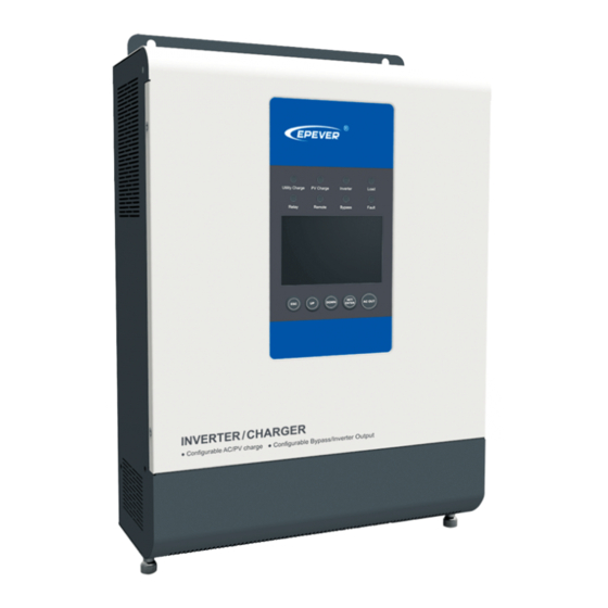
1.2 Characteristics Figure 1 Product appearance ★ ① ⑦ Mounting Hole interface ② ⑧ Captive screw (2) Relay interface ③ ⑨ AC output terminal Remote interface ④ ⑩ Utility input terminal Reserved communication interface ⑤ ⑪ Ground terminal Inverter/charger switch ⑥... -
Page 9: Designations Of Models
1.3 Designations of models 1.4 Schematic Diagram for Connections Warning:Confirm the AC equipment according to the power of the inverter/charger selected, the maximum power value that exceeds its power, therefore is prohibited. -
Page 10: Installation Instructions
2. Installation Instructions 2.1 General Installation Notes Please read the entire installation instructions to get familiar with the installation steps before installation. Be very careful when installing the batteries, especially flooded lead-acid battery. Please wear eye protection, and have fresh water available to wash and clean any contact with battery acid. - Page 11 Recommended wire and circuit breaker of PV Model PV wire size Breaker UP1500-M3222 10mm /8AWG 2P—63A UP2000-M3322 10mm /8AWG 2P—63A UP3000-M3322 10mm /8AWG 2P—63A UP3000-M2142 /10AWG 2P—32A NOTE: When the PV modules connect in series, the open circuit voltage of the PV array must not exceed 92Vor 138V at 25℃...
-
Page 12: Mounting
2.3 Mounting Figure2-1 Mounting Installation steps: Step1:Determination of Installation Location and Heat-dissipation Space Determination of installation location: The inverter/charger shall be installed in a place with sufficient air flow through the radiators of the controller and a minimum clearance of 150 mm from the upper and lower edges of the controller to ensure natural thermal convection. - Page 13 Step 3:Wiring Figure 2-2 Wring Diagram load PV array Utility Connect the system in an order of battery in accordance with Figure 2-2: Wiring Diagram and disconnect the system in the reverse order. Warning: Danger, High-voltage! Utility input, AC output and PV array will produce very high voltage, make sure to disconnect the circuit breaker/ fuse before wiring.
- Page 14 and place the other end close to the battery. NOTE: The temperature sensor short-circuited or damaged, the inverter/charger will be charging or discharging at the default temperature 25℃. Step 7:Recheck if the wire connection is correct Step 8:Powered on the inverter/charger ①Turn on the circuit breaker at the battery end.
-
Page 15: Interface Instruction
3. Interface Instruction 3.1 Indicator Indicator Color Status Instruction No utility Utility connection normal but no On Solid charging Green Slowly Flashing Utility charging Fast Flashing Utility charge module fault No PV PV connection normal but no charging On Solid Green Slowly Flashing PV charging... -
Page 16: Buttons
3.2 Buttons Operation Instruction Exit the current interface Press the button Clear the faults Press the button and hold on 5s Browse interface:Up/Down Press the button Setting interface:Up/Down Switch to "Browse Parameter Column" Press the button Determine the setting parameters Switch the"... - Page 17 Battery capacity level Battery capacity level 8~25% 25~50% Battery capacity level Battery capacity level 50~75% 75~100% Item Setting Content Solar priority Utility priority ① INPUT Utility & solar Solar Battery ② OUTPUT Utility AC output voltage AC output current ③ Load AC output power AC output frequency...
- Page 18 ① INPUT Solar priority The battery is charged in solar priority mode and when the battery voltage is lower than “Restore Auxiliary Module Charging Voltage(V )”, the utility starts charging. When the battery voltage reaches to “Stop Auxiliary Module Charging Voltage(V )”, the utility stops charging.
-
Page 19: Setting Interface
3.4 Setting interface Common interface Operation: Step1: Press the button and hold on 5s under the real-time interface. Step2: Press the button and hold on 5s under the setting parameter interface. Step3: Press the button to enter the parameter. Step4: Press the button to exit the setting interface. - Page 20 2) Advanced interface Operation: Step1: Press the button and hold on 5s under the real-time interface. Step2: Press the button and hold on 5s under the setting parameter interface. Step3: Press the button to enter the parameter. Step4: Press the button to exit the setting interface.
-
Page 21: Other Function
NOTE: 15/16:Stop/restore auxiliary module charging voltage Only when the charging mode is Solar priority or Utility priority will the auxiliary module charging voltage be effective. 20:Power saving mode When the power saving mode switch is in ON state, and when the load is less than 40W, the cycles of AC output for 5s, and no-output for 10s are excuted. - Page 22 NOTE: When the utility input is abnormal, this dry contact can control the oil engine switch to charge the battery. 1) Remote interface 2) Remote interface input voltage( 3.3~ 12V ) (1)The input voltage Vi is within 2.5~ 10s, the AC output state is reversed (when the AC is formerly in output state, now it is in no-output state ;...
-
Page 23: Protection
4. Protection Protection Instruction When the charging current of the PV array exceeds its rated current, it will be charged at the rated current. NOTE: When the PV modules are in series, ensure that the open-circuit voltage of the PV array does not exceed the "maximum PV PV Over Current open-circuit voltage". -
Page 24: Troubleshooting
5. Troubleshooting 5.1 Fault battery Fault Module Code Fault frame indicator Buzzer indicator blink — — Battery over voltage Battery low voltage — Battery Flashing Battery over discharge Nominal voltage error Low temperature over temperature (PV charge module) PV charge charging Communication Fault Fast Flashing... -
Page 25: Maintenance
6. Maintenance 1)The following inspections and maintenance tasks are recommended at least two times per year for best performance. Make sure inverter/charger firmly installed in a clean and dry ambient. Make sure no block on air-flow around the inverter/charger. Clear up any dirt and fragments on radiator. -
Page 26: Technical Specifications
7. Technical Specifications Item UP1500-M3222 UP2000-M3322 UP3000-M3322 UP3000-M2142 System battery 24VDC 48VDC voltage Battery input voltage 21.6~31.9VDC 43.2~63.9VDC range Inverter output Output rated power 1200W 1600W 2400W 2400W Output power (15min.) 1500W 2000W 3000W 3000W Overload power(5s) 2400W 3200W 4800W 4800W Max. - Page 28 BEIJING EPSOLAR TECHNOLOGY CO., LTD. Tel: +86-10-82894112 / 82894962 Fax: +86-10-82894882 E-mail:info@epsolarpv.com Website: http://www.epsolarpv.com/ http://www.epever.com/...
Need help?
Do you have a question about the UP1500-M3222 and is the answer not in the manual?
Questions and answers
How many solar panels must I connect when using epever up1500?
The Epever UP1500-M3222 has a maximum PV input power of 3000W and a maximum PV charging current of 60A. The number of solar panels that can be connected depends on the power and voltage ratings of the panels used.
For example, if using 300W solar panels:
- 3000W ÷ 300W per panel = 10 panels (assuming the voltage and current are within the acceptable range).
The exact number of panels depends on their specifications and how they are connected (series or parallel) to meet the system's voltage and current limits.
This answer is automatically generated