
Related Manuals for Epever UPower Series


Summary of Contents for Epever UPower Series
- Page 1 UPower Series ——Inverter/charger User Manual Models: UP1000-M3212/UP1000-M3222 UP1500-M3222/UP2000-M3322 UP3000-M3322/UP3000-M2142 UP3000-M6142/UP3000-M6322 UP5000-M6342/UP5000-M8342 UP5000-M10342...
-
Page 3: Important Safety Instructions
Important Safety Instructions Please reserve this manual for future review. Please reserve this manual for future review. This manual contains all instructions about safety, installation and operation for the inverter/charger. Read carefully all the instructions and warnings in the manual before installation. ... -
Page 4: Table Of Contents
CONTENTS 1. General Information ................ 1 1.1 Overview ..................1 1.2 Characteristics ................2 1.3 Designations of models ..............3 1.4 Schematic Diagram for Connections ........... 3 2. Installation Instructions ..............4 2.1 General Installation Notes ............. 4 2.2 Wire Size& breaker ................ 4 2.3 Mounting .................. -
Page 5: General Information
1. General Information 1.1 Overview The UPower series is a new type of the inverter/charger combining with solar & utility charging and AC output, which adopts a multi-core processor design and advanced MPPT control algorithm, and has the features of high response speed, high reliability and high industrialization standard. It offers four charging modes including Solar priority, Utility priority, Solar and Utility &... -
Page 6: Characteristics
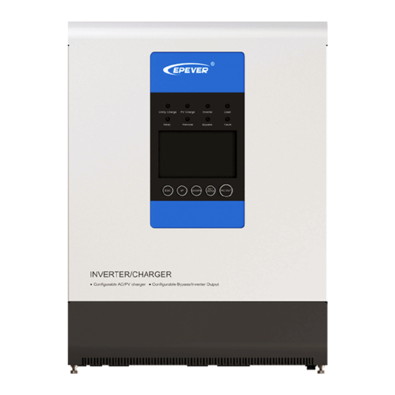
1.2 Characteristics Figure 1 Product appearance ❶ ❼ Ventilation Relay interface ❽ ❷ Captive screw (2 pcs) Remote interface ❸ ❾ AC output terminals Inverter/charger switch ❹ ❿ Utility input terminals PV input terminals ❺ ⓫ Battery input terminals Terminals cover ❻... -
Page 7: Designations Of Models
Temperature Sensor (Model:RT-MF58R47K3.81A) NOTE: ★ Connect the temperature sensor, the inverter/charger is compensated according to the ambient temperature. 1.3 Designations of models 1.4 Schematic Diagram for Connections Warning:Confirm the AC load power compatible with the power of the inverter/charger, AC load selected exceeding the maximum output power of inverter/charger is prohibited. -
Page 8: Installation Instructions
2. Installation Instructions 2.1 General Installation Notes Please read the entire installation instructions to get familiar with the installation steps before installation. Be very careful when installing the batteries, especially flooded lead-acid battery. Please wear eye protection, and have fresh water available to wash and clean if any contact with battery acid. ... - Page 9 UP1500-M3222 10mm /8AWG 2P—63A UP2000-M3322 10mm /8AWG 2P—63A UP3000-M3322 10mm /8AWG 2P—63A UP3000-M6322 16mm /5AWG 2P—100A UP3000-M2142 /10AWG 2P—32A UP3000-M6142 16mm /5AWG 2P—100A UP5000-M6342 16mm /5AWG 2P—100A UP5000-M8342 25mm /4AWG 2P—125A UP5000-M10342 25mm /4AWG 2P—125A NOTE: When the PV modules connect in series, the open circuit voltage of the PV array must not exceed max.
-
Page 10: Mounting
Recommended wire and circuit breaker for AC output Model AC wire size Breaker UP1000-M3212 2.5mm /14AWG 2P—10A UP1000-M3222 2.5mm /14AWG 2P—10A 2.5mm /14AWG UP1500-M3222 2P—10A UP2000-M3322 2.5mm /14AWG 2P—16A UP3000-M3322 /12AWG 2P—25A UP3000-M6322 /12AWG 2P—25A UP3000-M2142 /12AWG 2P—25A UP3000-M6142 /12AWG 2P—25A UP5000-M6342... - Page 11 Installation steps: Step1:Determination of Installation Location and Heat-dissipation Space Determination of installation location: The inverter/charger shall be installed in a place with sufficient air flow through the dissipation pad of the inverter/charger and a minimum clearance of 150 mm from the upper and lower edges of the inverter/charger to ensure natural thermal convection.
- Page 12 load PV array Connect the system in an order of battery GroundUtility in accordance with Figure 2-3: Wiring Diagram. Disconnect the system in the reverse order. Warning: Danger, High-voltage! Utility input, AC output and PV array will produce dangerous voltage, make sure to disconnect the circuit breaker/ fuse before wiring.
- Page 13 NOTE: In case the power is supplied to the different AC loads, it is suggested to turn on the loads with larger surge current, till the load working well, then turn on the loads with smaller surge current. NOTE: In case the inverter/charger is not in normal operation, or LCD or indicator displays abnormal, refer to Section 5 to clear the fault or contact the after-sale service personnel of our company.
-
Page 14: Interface Instruction
3. Interface Instruction 3.1 Indicator Indicator Color Status Instruction No utility input Utility connection normal but no On Solid charging Green Slowly Flashing(0.5Hz) Utility charging Fast Flashing(2.5Hz) Utility charge module fault No PV input connection normal On Solid charging Green Slowly Flashing(0.5Hz) PV charging Fast Flashing(2.5Hz) -
Page 15: Buttons
3.2 Buttons Operation Instruction Exit the current interface Press the button Clear the faults Press the button and hold on 2s Browse interface:Up/Down Press the button Setting interface:Up/Down Switch to “Browse Parameter Column" Confirm the setting parameters Press the button Switch the"... - Page 16 Load power 8~25% Load power 25~50% Load power 50~75% Load power 75~100% Item Setting Content Solar priority Utility priority ① INPUT Utility & solar Solar Battery ② OUTPUT Utility AC output voltage AC output current ③ Load AC output power AC output frequency Battery voltage Max.
- Page 17 Float ⑦ Battery charging stage Boost Equalize(28 each month) ① INPUT ★Solar priority(Default) The battery is charged in solar priority mode and when the battery voltage is lower than “Auxiliary )”, the utility starts charging. When the battery voltage reaches to Module ON Voltage(V “Auxiliary Module OFF Voltage(V )”, the utility stops charging.
-
Page 18: Setting Interface
★Utility(Default) 3.4 Setting interface Common interface for common user Operation: Step1: Press the button and hold on 2s at the real-time interface to go to the common interface. Step2: Press the button and hold on 2s at the setting parameter interface and choose the parameters. - Page 19 ℃ ℃/℉ Temperature unit Backlight time 30S/60S/100S(ON) Buzzer alarm switch ON/ OFF ★ User 21.0~22.6V ★ Low voltage disconnect voltage 21.6V ★ step size 0.2V ★ User 24.0~26.0V ★ Low voltage reconnect voltage 25.0V ★ step size 0.2V ★The voltage parameter are at 25℃, 24V system, and twice in 48V system. NOTE: When Output source priority is Battery and the battery voltage lower than the Low Voltage Disconnect Voltage(LVD adjustable), the system will switch utility to supply power for load.
-
Page 20: Other Function
Clear the accumulated energy ON/OFF 100~4000AH Total battery capacity 600AH Step size 100AH — Software version U-1.0 ★The voltage parameter are at 25℃, 24V system (twice in 48V system). ◆For the inverter/charger of different power, the current setting range is not the same, see Technical Parameters for details. - Page 21 2)Relay interface Working principle: When the battery voltage reaches the Low Voltage Disconnect Voltage (LVD) , the coil of relay is energized, and the switch is turned on. The dry contact can drive resistive loads 125VAC /1A, 30VDC/1A. 3) Remote interface Remote interface input voltage (3.3~12V) (1)The input voltage Vi is within 2.5~ 10s, the AC output state is reversed (when the AC is formerly in output state, now it is in no-output state ;...
-
Page 22: Protection
4. Protection Protection Instruction When the charging current of the PV array exceeds its rated current, it will be charged at the rated current. PV limit Current NOTE: When the PV modules are in series, ensure that the open-circuit voltage of the PV array does not exceed the "maximum PV open-circuit voltage". -
Page 23: Troubleshooting
5. Troubleshooting 5.1 Fault battery Fault Module Code Fault indicator Buzzer frame indicator blink — — Battery low voltage Battery over voltage — Battery over discharge Battery Flashing Nominal voltage error Low temperature over temperature PV charge (PV charge module) charging Fast Communication Fault... -
Page 24: Maintenance
6. Maintenance 1)The following inspections and maintenance tasks are recommended at least two times per year for best performance. Make sure inverter/charger firmly installed in a clean and dry ambient. Make sure no block on air-flow around the inverter/charger. Clear up any dirt and fragments on radiator. -
Page 25: Technical Specifications
7. Technical Specifications Item UP1000-M3212 UP1000-M3222 UP1500-M3222 UP2000-M3322 UP3000-M3322 UP3000-M6322 System battery voltage 12VDC 24VDC Battery input voltage range 10.8~16VDC 21.6~32VDC Inverter output Continuous output power 800W 800W 1200W 1600W 2400W 2400W Output power (15min.) 1000W 1000W 1500W 2000W 3000W 3000W Overload power(5s) 1600W... - Page 26 Temperature -3mV/℃/2V (Default) compensate coefficient Others ≤1.2A ≤0.6A ≤0.6A ≤0.8A ≤0.8A ≤0.8A No load consumption Enclosure IP30 Relative humidity < 95% (N.C.) Working environment -20℃~50℃(100% input and output) temperature Mechanical Parameters Dimension 386×300×126mm 444×300×126mm 518×310×168mm Mounting dimension 230mm Φ8mm Mounting hole size Weight 7.3kg 7.3kg...
- Page 27 ★ ★ 150V 200V Max. PV open circuit ◆ ◆ voltage 138V 180V Max. PV input power 1040W 3000W 3000W 4000W 5000W Max. PV charging current 100A Equalization voltage 58.4V Boost voltage 57.6V Float voltage 55.2V ≤99.5% Tracking efficiency Charging conversion ≤98% efficiency Temperature...
- Page 28 BEIJING EPSOLAR TECHNOLOGY CO., LTD. Tel: +86-10-82894112 / 82894962 Fax: +86-10-82894882 E-mail:info@epsolarpv.com Website: http://www.epsolarpv.com/ http://www.epever.com/...
Need help?
Do you have a question about the UPower Series and is the answer not in the manual?
Questions and answers